PAL UpdatesComments Off on Dyna Gears PAL dump added
Nov092014
‘coolmod, one of our finest members, sent in the PAL dump from his Dyna Gears PCB.Dump was obtained from an unprotected GAL16V8 device and it’s tested as working.Thanks to him for this submission.
GuidesComments Off on Testing Bubble Bobble ROM banks with Fluke 9010
Nov012014
Recently I was talking to IronGiant about testing the “a78-05-1.52” ROM on an original Bubble Bobble PCB with the Fluke 9010.
As the ROM is banked we cannot test this ROM in one go.
Here is how we managed to do it.
0) Before we do anything we need to disable the watchdog otherwise this wont work properly. This is done by cutting the track on JP6 on the solder side (thanks to IronGiant for the info).
1) Take the ROM dump for “a78-05-1.52” and split it into 4 files using a HEX editor or similar. Each file should be 0x4000 bytes in size.
Run all 4 files through one of the signature calculators that can be found online and make a note of them.
2) The bankswitch lies at address 0xFB40 in the address map.
You need to write a value between 4 and 7 to select the relevant bank.
So start by writing 4 to address 0xFB40.
3) Next we need run a ROM check on between address 0x8000 & 0xBFFF.
This signature should match the first 0x4000 bytes of the ROM.
4) Repeat steps 2 and 3 a further three times incrementing the value written to address 0xFB40 each time. If all the signatures match then the ROM is good.
The ROM is different across each version of this game so make sure you compare it with the right file.
This method will probably work on the bootlegs too with some minor changes to the procedure.
PAL UpdatesComments Off on SEGA System C/C2 PAL dumps added
Oct302014
Today I’ve added to our database two of the three PALs dumps (the one stamped ‘315-5394’ is registered) coming from an original Sega Columns PCB.These PALs should be present on all games that run on Sega System C/C2 hardware.Dumps are tested and working on a GAL16V8 targeting device.Just a technical note : the PAL marked ‘315-5395’ was manually reversed by Porchy (thanks to him!) since it has latches built-in.If you want to go into that, I recommend reading this document about PLDs:
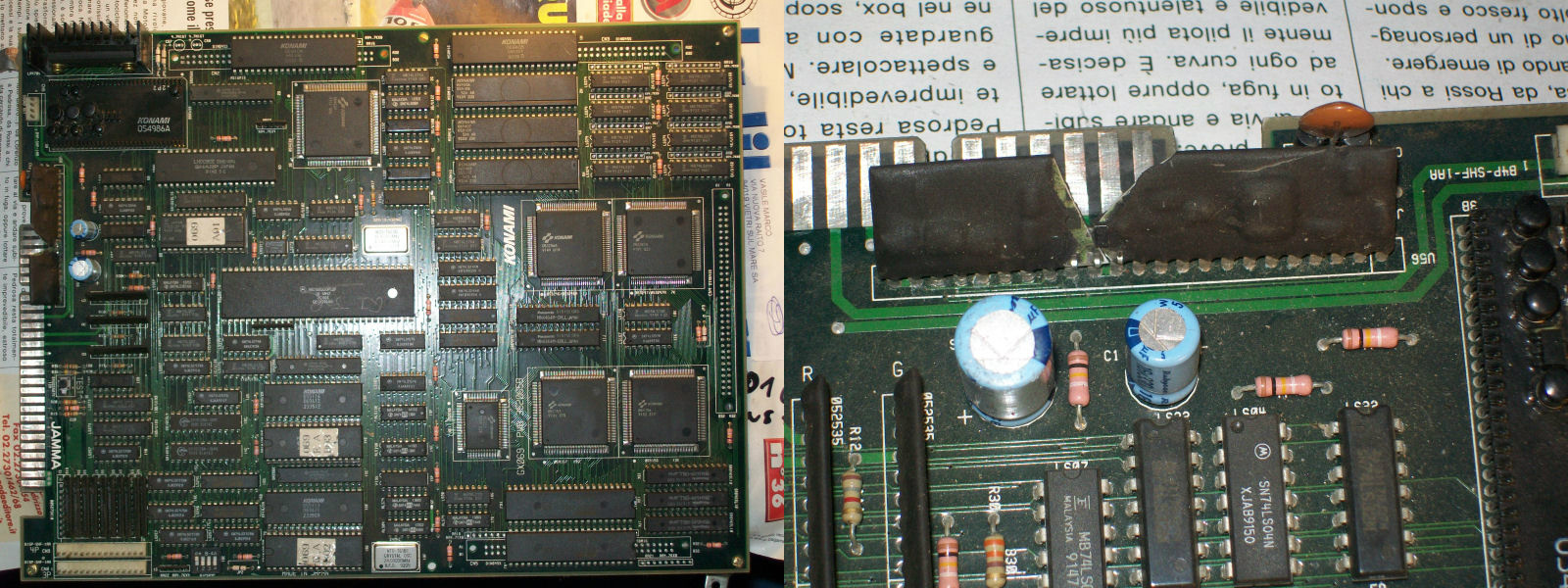
Got this original Konami G.I. Joe PCB from Ebay as not working.Looking at the auction picture I could see the ‘051550’ SIL custom broken in half, this was confirmed once I received the board:
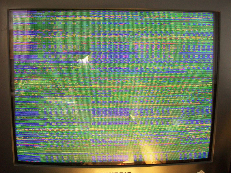
For the uninitiated, this custom is of vital importance since it generates the master RESET for the whole board, infact 68000 CPU RESET line was stucked LOW and I got only a static screen:
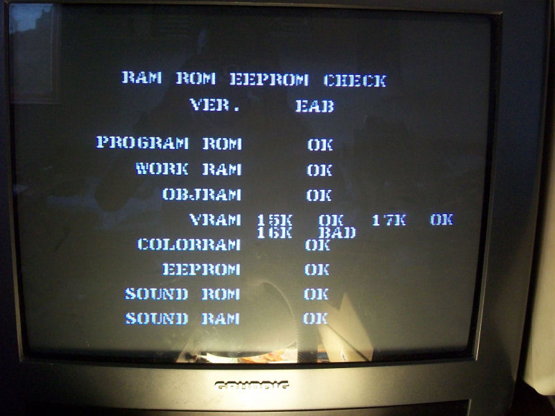
I had many Konami faulty boards for spare so I took this custom from one of them and, after replaced it, the board resetted properly but with an error on VRAM @16K:
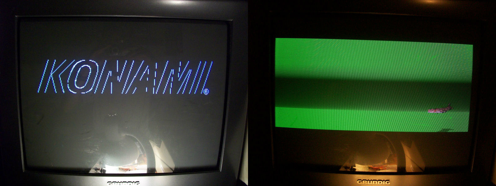
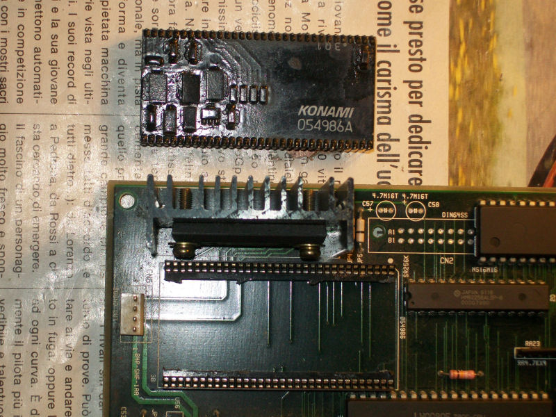
Desoldered and test the 6264 RAM out-of-circuit confirmed it as bad.With a new RAM game was fully playable (also with sound which is quite rare as this board uses the ‘054986A’ hybrid custom module) but something was wrong :
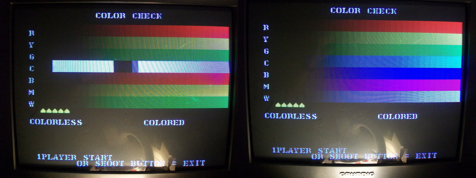
like some colours were missing from certain backgrounds and this was confirmed also by the color check I ran in TEST MODE comparing the output with the one from a working board:
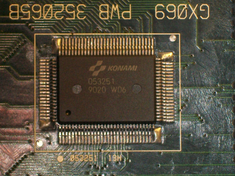
Color RAM was OK as reported by initial test so I start to suspect the ‘053251’ ASIC since I had a similar fault on a Bell & Whitles PCB.According to MAME this ASIC is a palette/priority chip :
So this convinced me to replace it.And I was right since colours came back to normality:
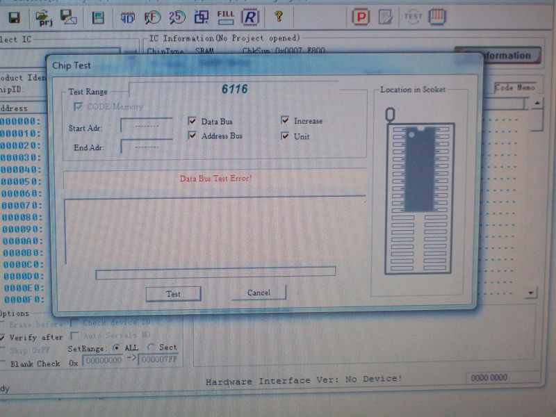
Gameplay was fine now but some of the sound FXs were muffled and distorted.It could not be due the ‘054986A’ hybrid module since the issue was limited only to some FXs so I started to check the audio circuit (commanded by the usual Z80 CPU).When I piggybacked the 6116 SRAM @6C all the sound FXs were restored so I desoldered the chip in order to test it out-of-circuit:
RAM was really bad though this fault was not reported by initial RAM/ROM test.Not satisfied, finally, to top it all I recapped (with tantalum capacitors) and socketed the ‘054986A’ sound hybrid module’: