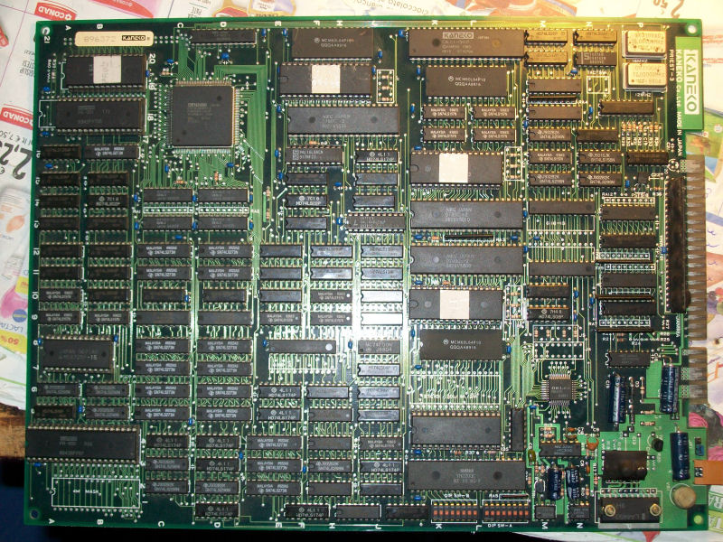
Bought this mint original Kaneko Air Buster PCB from my friend Corrado:
PCB was working fine but sound samples (drums, bass line, etc..) were played sometimes randomly other times in a bad way:
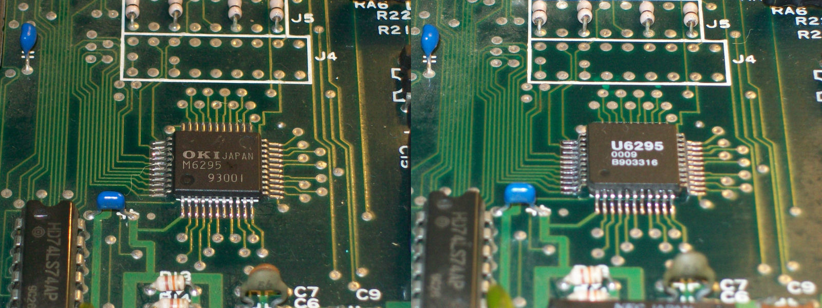
In this PCB (and a lot of other similar audio hardware) samples are played by the OKI MSM6296 chip which take DATA directly from the ROM that I dumped as good.Connecting an external AMP to pin 36 of the OKI6295 (this pin is the digital-to-analog converted signal fed into the UPC324 OP-AMP, you can download its datasheet here in the downloads section ) I had the same issue so this convinced me to replace the chip (with a rebadged one but it’s the same):
PAL UpdatesComments Off on Choplifter PAL dumps added
Dec232014
We have had a zip file for Choplifter in the archive for a while now and I finally got the chance to test them.
One of them was a CK2605 which I dumped myself as a PLS153 and is assumed working but the other two were from a PAL16R4 device and they both work fine.
A bit late posting this one but here it is.
Runik has been working really hard to get this done. It is partially tested right now by muddymusic and the game boots but his board set has a graphics fault so at this point it still needs further testing. If you are able to test then please let us know.
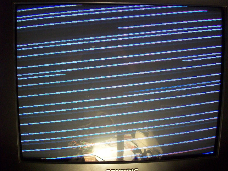
Another Rainbow Islands on the bench, this one from my friend “Mikidaffy1983”:
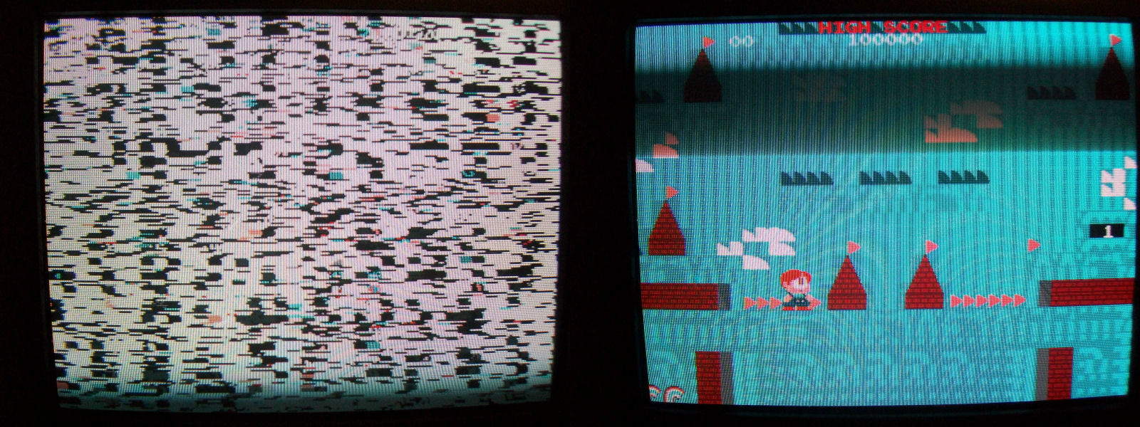
Board was in excellent state but when powered on all I got was a screen of wavy lines:
Started my usual visual inspection and didn’t notice nothing odd but when touched the PAL “B22-05” @IC33 I found it quite hot.Probing its outputs I found they were almost all dead so I programmed a GAL16V8 with the replacement hosted on this site (thank you Porchy and Macro for this).With the PAL replacement fitted the board succesfully booted but sometimes stuck on a static black/white striped screen , others times with bad/missing backgrounds:
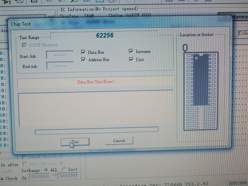
Since I repaired other Rainbow Islands (and similar hardware like Bonze Adventure) I knew tiles are generated by the custom marked ‘PC080SN’ @IC34.This custom is connected to two 62256 SRAMs so I analized them with a logic probe and found that most DATA lines of the one @IC3 were stuck HIGH or LOW.Without thinking twice I desoldered and tested it having confirm it was bad:
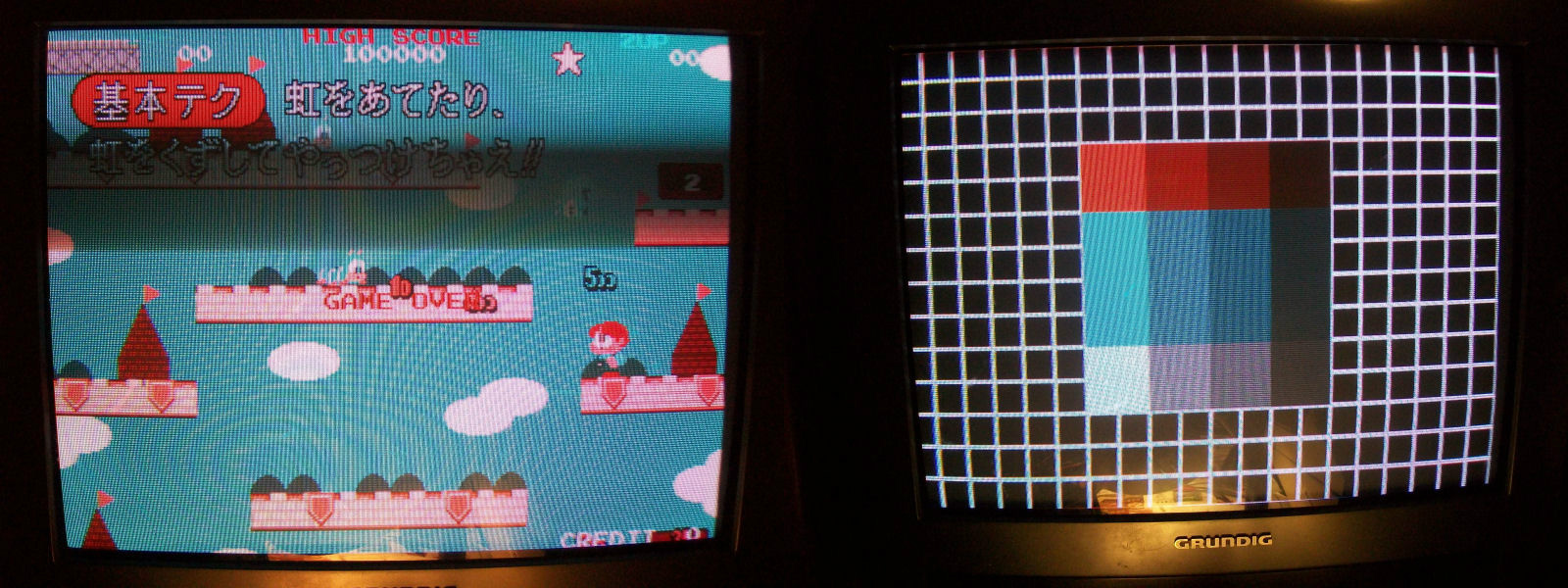
Fitted a new 62256 SRAM led me to this point:
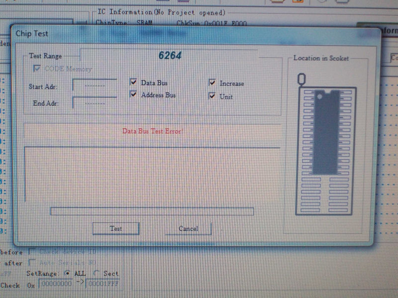
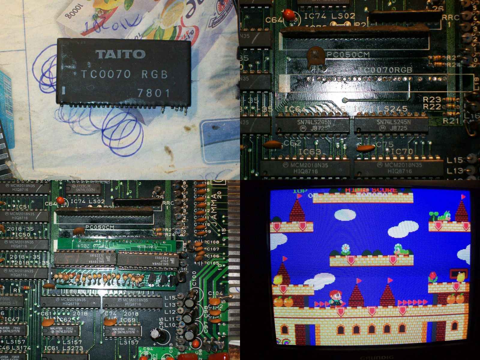
All backgounds/tiles were restored but there was a clear issue with the blue color.As we know RGB colors are generated by the custom module ‘TC0070RGB’ which on this PCB was resoldered but after a comparison with a good board I couldn’t find anything strange so I decided to move ahead and look into other issues.In particular there was no sound at all, only a buzzing noise sign that the main MB3735 amplifier was good.There was also no sound ouput from YM3012 DAC and this convinced me look into the digital part of the audio circuit.Probing the 6264 SRAM @IC44 revealed weird activity on its DATA/ADDRESS lines, testing it out-of-circuit confirmed it was bad:
Sound was fully restored but it was quiete and faint also at the highest volume.Connecting an external AMP to the inputs of the TL074 OP-AMP @IC67 gave me strong and steady volume so I rightly replaced this IC.
Back to the blue color issue I decided to go straight and remove the TC0070RGB module installing the Macro replacement resulting in a success.Board 100% fixed.
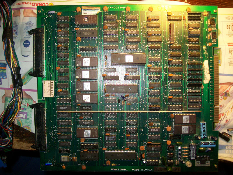
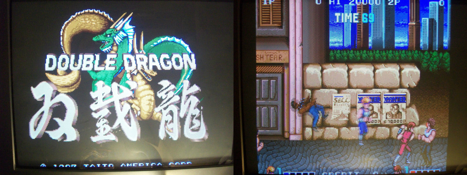
Found this PCB in the pile, honestly I can’t remember when and where I got it :
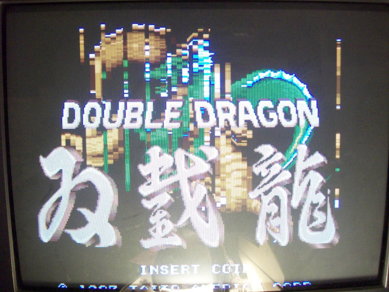
Once powered ON I was greeted by this title screen:
Also sprites in game were all blocky with some parts floating on the screen:
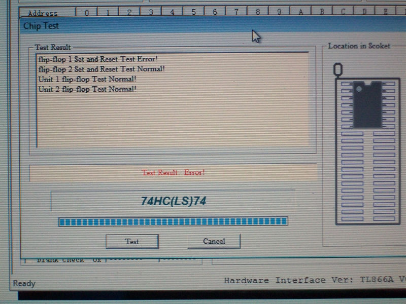
I also noticed that some sound FXs (especially speeches) were missing so I decided to first troubleshoot this issue.Probing one of the OKI MSM5205 @IC81 I found that all four data outputs were not toggling.The chip read data from the two samples EPROMs not directly but through two 74LS157 multiplexers.I found that select line (PIN1) of the one @IC96 was stuck HIGH so data inputs were not selected at all.I traced it back to an output (PIN3) of the 74LS393 @IC62 so I desoldered it but it was good.Probing the its CLEAR pin I found that it was stuck HIGH.Tracing it back lead me to an output (PIN6) of a 74LS74 @IC75. I desoldered it and tested it out-of-circuit having confirm that it was bad:
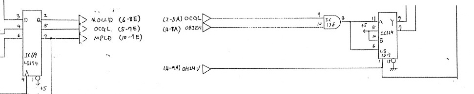
With sound FXs fully restored I decided to come back to the sprites issue.Fault was located in the VIDEO board since I swapped a good one and issue sprites came back normal.Luckily we have schematics so I started to check for parts of circuits involved in the sprite generation and handling but after two days of troubleshooting and a lot of suspected ICs replaced in vain I came to a dead end.I was nearly to give up and declare the board as not repairable but checking the last part of the object generation schematics I found a missing signal input (called ‘OCGL’) on PIN9 of a 74LS08 @IC36.This signal is generated by an output (PIN5) of a 74LS174 @IC69 always on VIDEO board.
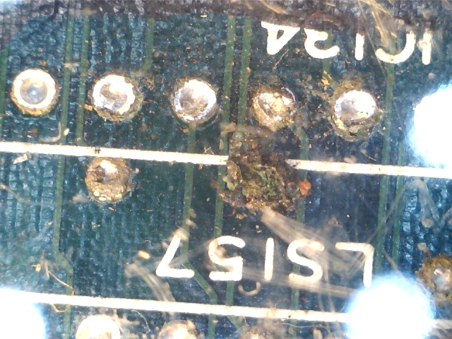
As I said this ‘OCGL’ signal was present as output of the 74LS174 but not as input of the 74LS08 so it was lost somewhere on the PCB.Following on solderside the traces between these two ICs I came across a via under a 74SL157 @IC34.I desoldered it and found this:
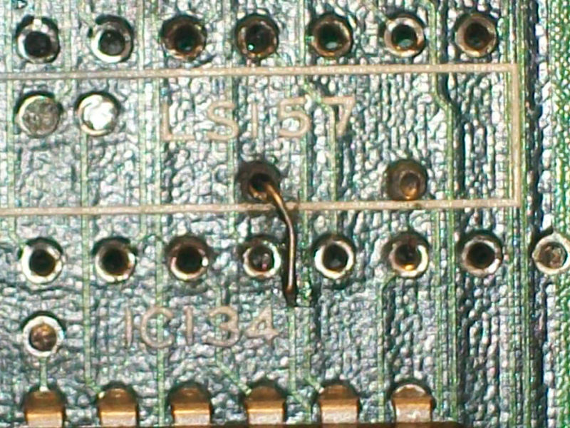
Oxid literally had corroded and eaten the pad and part of trace thus preventing the ‘OCGL’ signal reaching the input of the 74LS08.A tiny piece of AWG30 wire: