PAL UpdatesComments Off on Adventure Quiz Capcom World 2 (Japan 920611) PAL dump added
Jan302015
Today Bonky sent in a GAL16V8 replacement for the undumped ‘q522b’ @1A PAL from an Adventure Quiz Capcom World 2 (Japan 920611) CPS1 B-BOARD.Replacement was created by Neocps1 and tested by Bonky.Archive contains the .jed, .pld and .xml files.Thanks to both for their work.
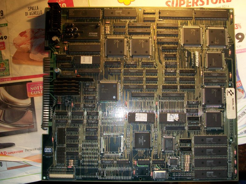
Got this faulty Violent Storm PCB from Ebay (well, actually seller sold me as Metamorphic Force one…)
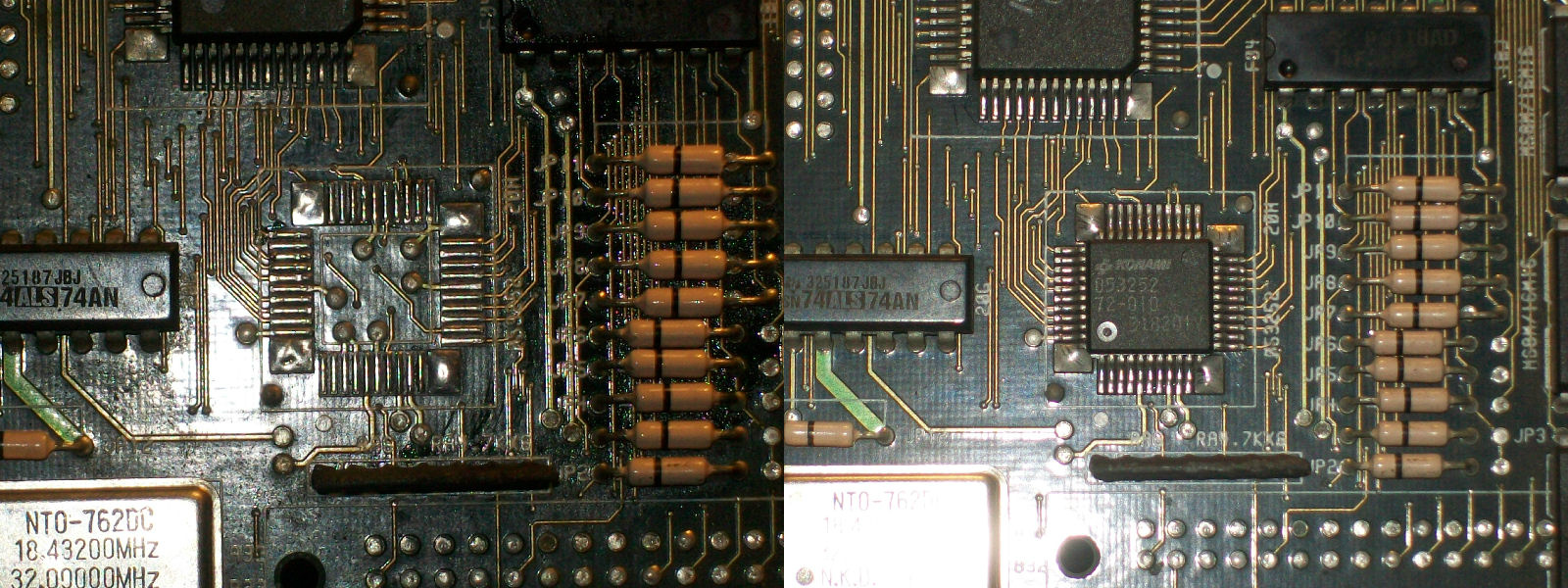
When I turned it on all I got was a solid black screen but this time watchdog circuit was not active.As many other Konami boards RESET signal is generated by PIN10 of the SIL custom ‘051550’.In this case signal was correct (first LOW then HIGH) but not on main CPU (an MC68H000GFN16 in PLCC package) where it was stuck LOW.So was time to investigate.I could trace RESET signal from PIN10 of the ‘051550’ custom to PIN7 of a custom marked ‘053252’ (44PIN in QFP package) while , from other side, RESET (PIN18) of the main 68000 CPU was tied to PIN12 of this ‘053252’ IC through some inverter gates (74F04).This was confirmed also by Metamorphic Force schematics (which runs on same indentical hardware) I could find at a later time:
As I said RESET signal was correctly generated by ‘051550’ custom, routed to ‘053252’ ASIC but then coming out from it stuck LOW.So with this assumption I had no other way than try to replace the ‘053252’ ASIC (in MAME source it’s indicated as CRT and interrupt control unit):
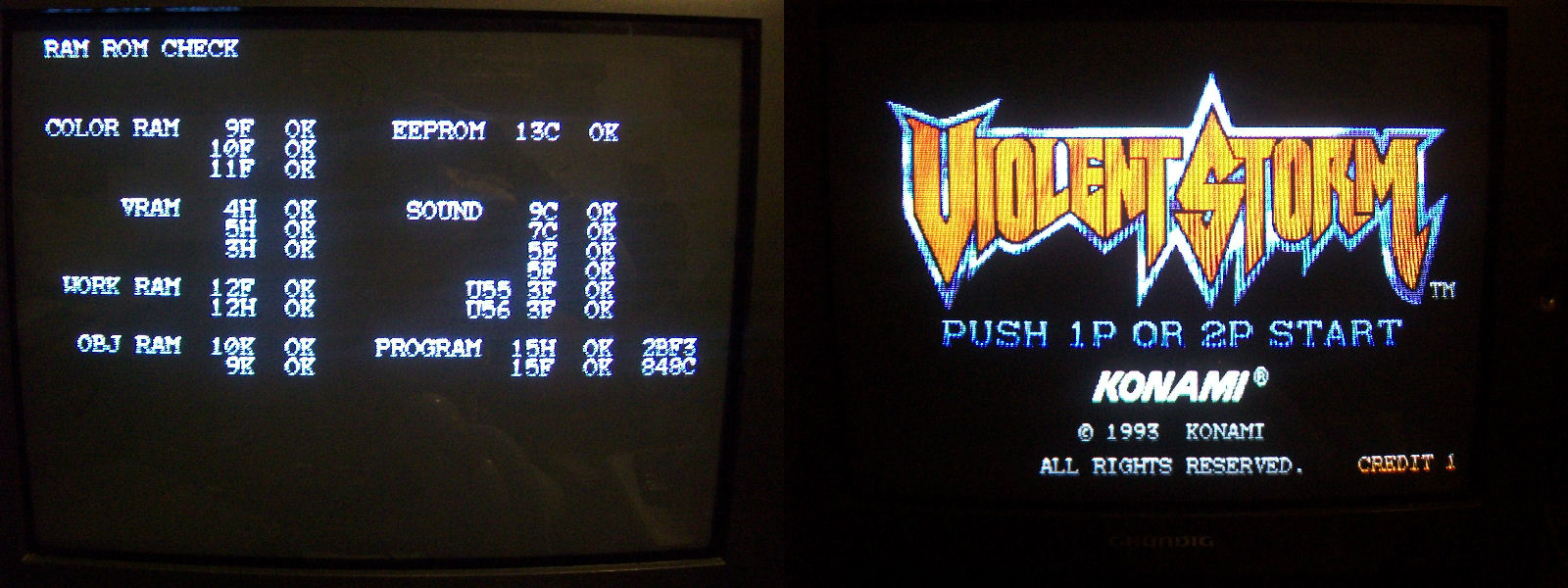
And I was right since board successfully booted and all was properly working:
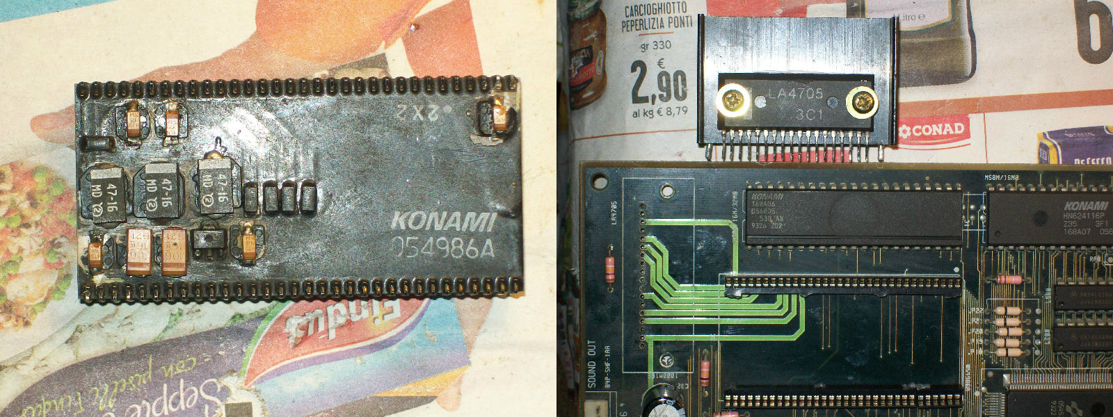
I was closing the case and declaring the board 100% fixed but the curse of the Konami hybrid sound module struck again!Infact while I was testing the board, the sound suddenly faded.But this time it was not only matter to replace all the SMT caps with tantalum ones but also the LA4705 audio amplifier broken due high ESR of the old caps and we all know that capacitors have the role to stabilize amplifier preventing its oscillation and failure:
That’s all for today, I hope you enjoyed this repair log!
PAL UpdatesComments Off on Zola-Puc Gal PAL dump added
Jan242015
Today Porchy dumped a PAL from a Zola-Puc Gal PCB.For the uninitiated, this game is a Pac-Man clone with some minor differences.Dump was obtained from a registered device so it’s an important achievement.It has been tested as working by Asure.Thanks to both.
PAL UpdatesComments Off on Violent Storm PAL dumps added
Jan242015
Today I dumped the two PALs (20 and 24 pin) from an original Konami Violent Storm PCB which was not working and now has been fixed (repair log will follow soon).Dumps are tested and working in a GAL16V8 and GAL22V10 replacement devices.
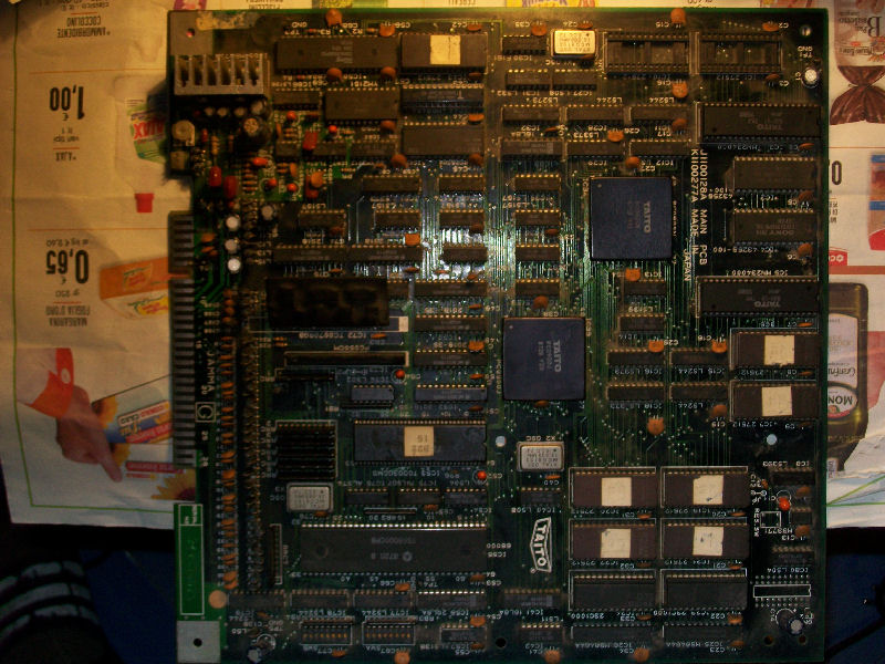
Yes, this is the third Rainbow Islands PCB (the fourth if we include the Extra version) I repaired.The PCB was in good state (dust apart):
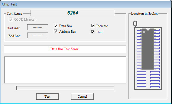
But all I get was a solid blank screen upon powered it on, no activities on DATA/ADDRESS bus of 68000 CPU, RAM and ROM.The program ROMs were dumped as good so I went to the two 6264 WORK RAMs @IC25 and @IC26 and, mindful of what had already happened with the other Rainbow Islands PCBs, I desoldered them and tested out-of-circuit.Both were bad!
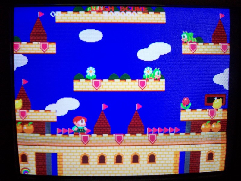
With new WORK RAMs fitted the board sometimes booted stuck on “OBJECT RAM ERROR” other times with jailbars all over the sprites:
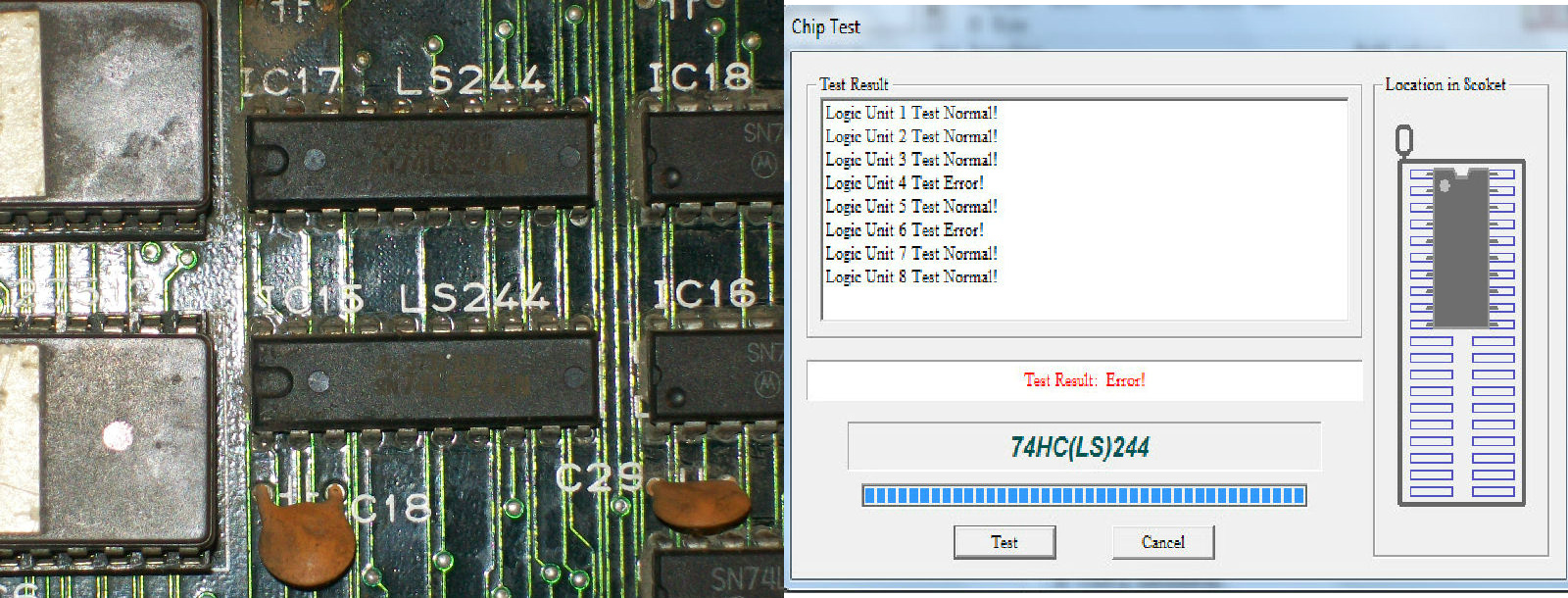
Jailbairs are a clear symptom of wrong written data.Sprite generation circuit on this PCB is made of a PGA custom ‘PC0900J’ , four 2018 SRAMs , some latches and buffers.Piggybacking the RAMs had no effect but when I made it on a 74LS244 @IC15 the jailbars faded and then disappeared completely when I piggybacked the other 74LS244 @IC17.
Desoldered them and tested out-of-circuit confirmed they were both bad:
Graphics were perfect at this point.Last issue to troubleshoot was the absolute lack of sound.When I was gonna to analyze the sound circuit I noticed @IC44 the 6264 RAM of the Z80 audio CPU was already socketed so I decided to test it resulting in a bad chip.Replaced it restored the sound.Board 100% fixed!