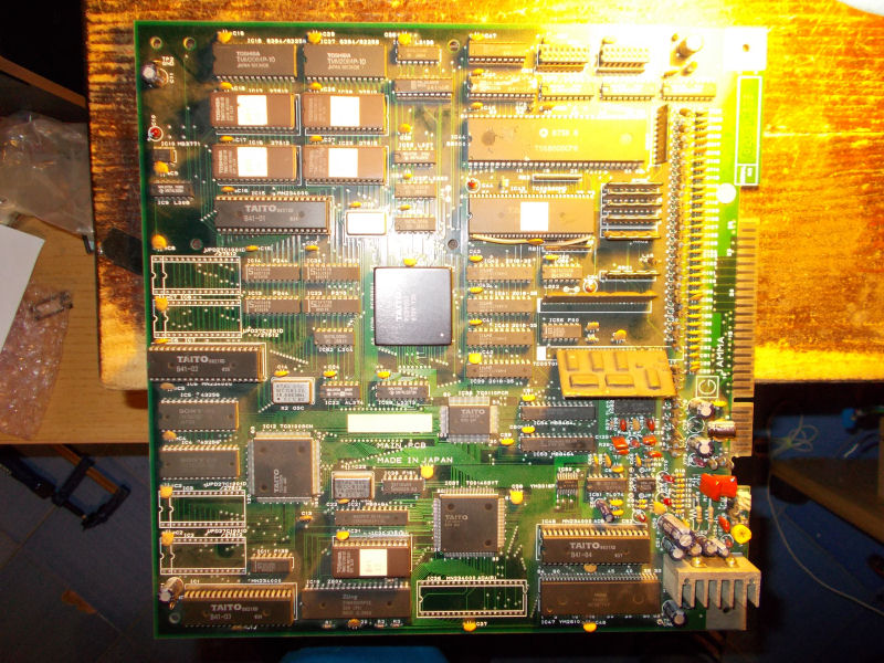
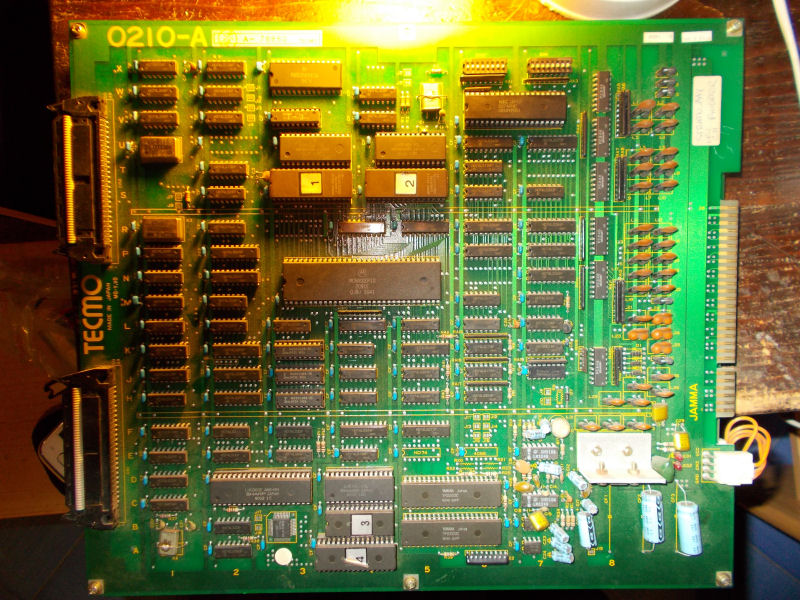
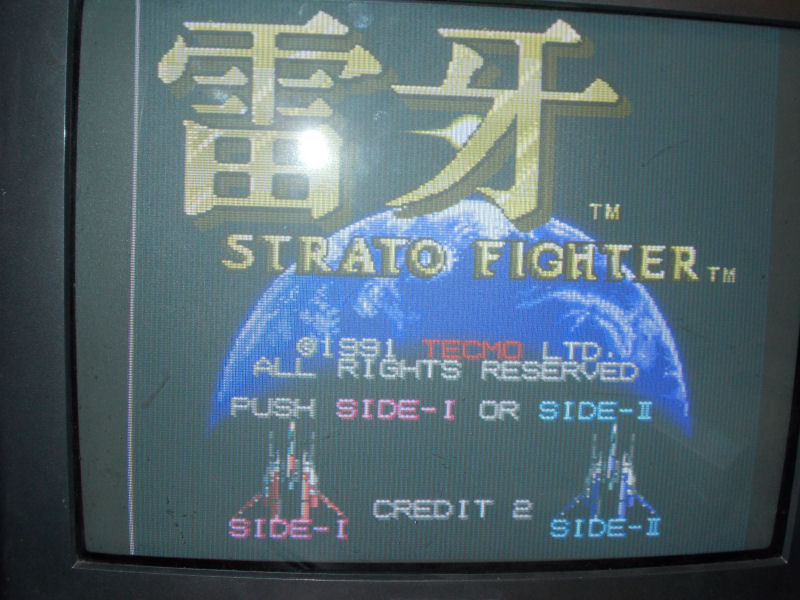
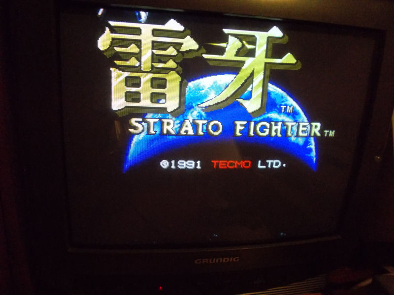
I got on the bench this Raiga – Strato Fighter PCB for a repair:
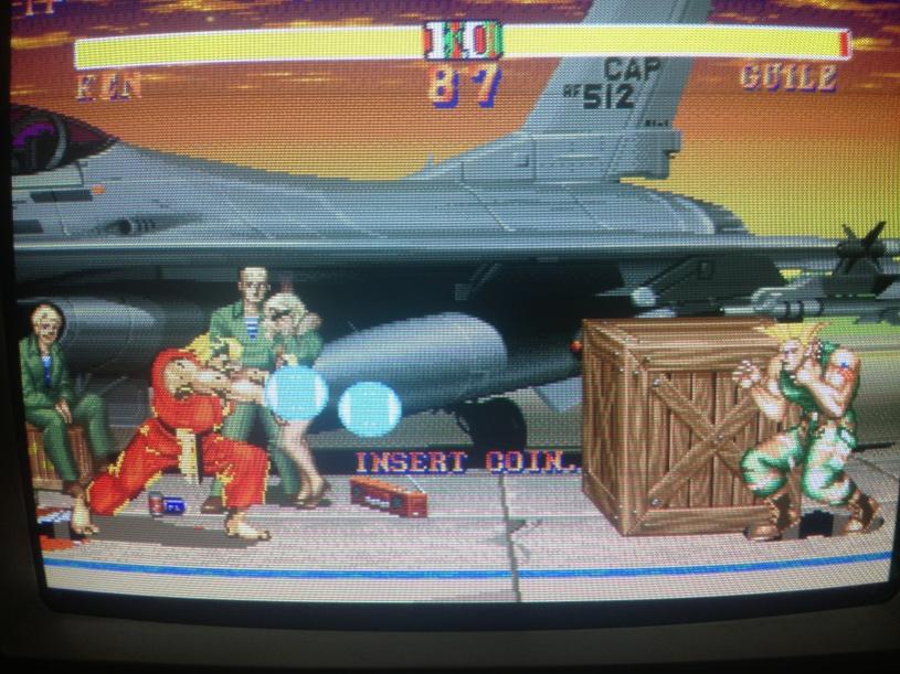
Game is a horizontal side-scrolling space shooter developed by Tecmo in 1991.Two were the issues I got when I powered it up.Sound was completely missing ( I got only some samples played randomly) and there were missing vertical lines all over the screen like a sort of scanlines effect:
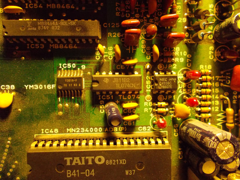
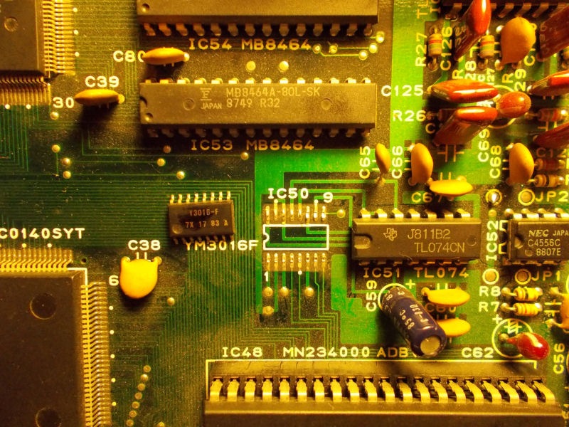
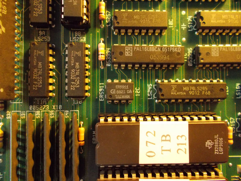
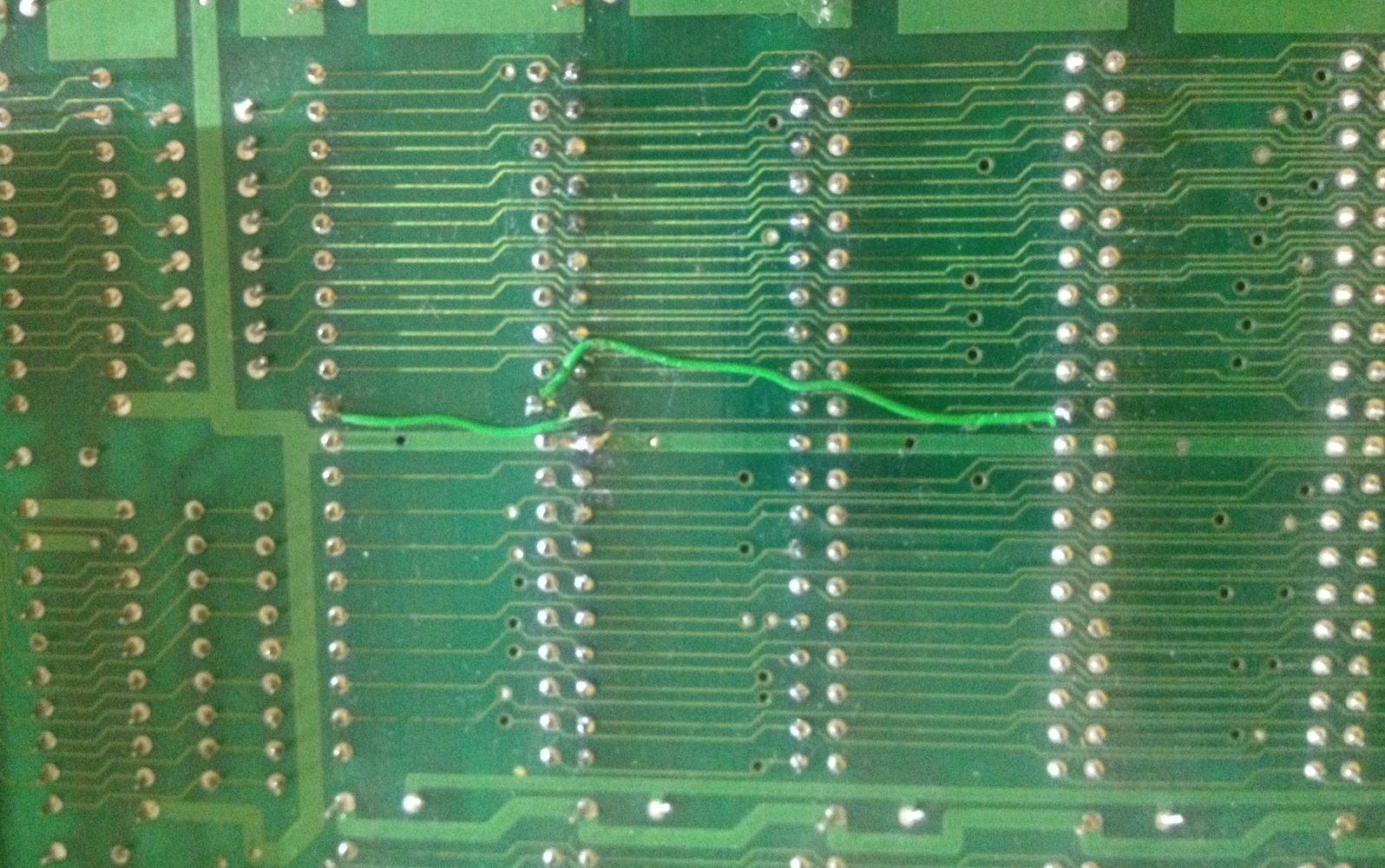
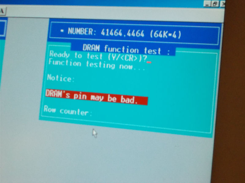
All video related circuitry is located on he bottom board.Since involved EPROMs and RAMs were socketed I could test them out-of-circuit and they were fine.Then I noticed some dynamic RAMs in form of 12 Sharp LH2464 (64K*4bit) chips.I went to probe them with my oscilloscope and I found weak signals on two data lines of a couple of them (good signal on left, bad on right of the below picture):

So, I removed the two chip and tested into my EPROM programmer where they both failed:
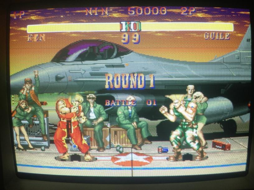
With two good DRAMs fitted, the graphics were completely restored:
So I went to troubleshoot the lack of sound.Main CPU of the audio digital section is a Z80 which commands two YM2203 FM sound synthesis chips for the music and one OKI 6295 for the voice samples.Probing the Z80 revealed random activity/pulsing on all its pins.Besides, chip was wery hot to the touch so I decided to replace it.This was the right move.Board 100% fixed.