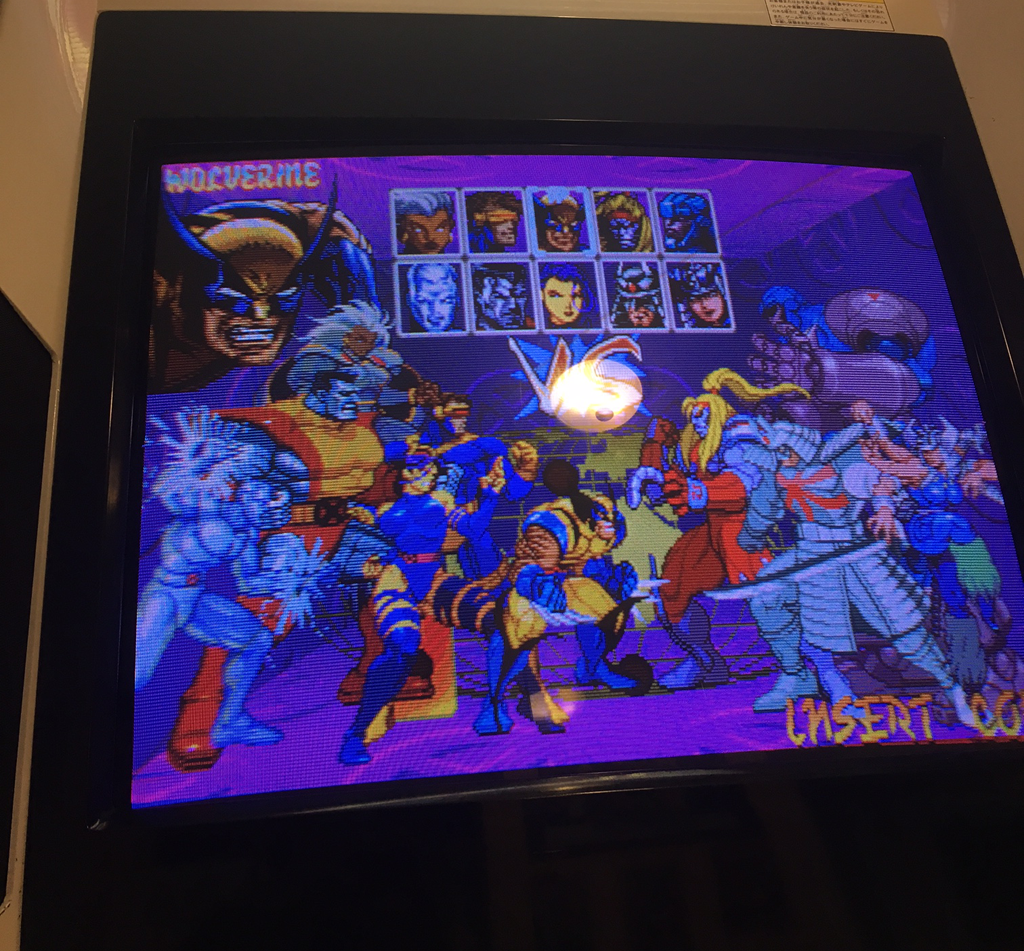
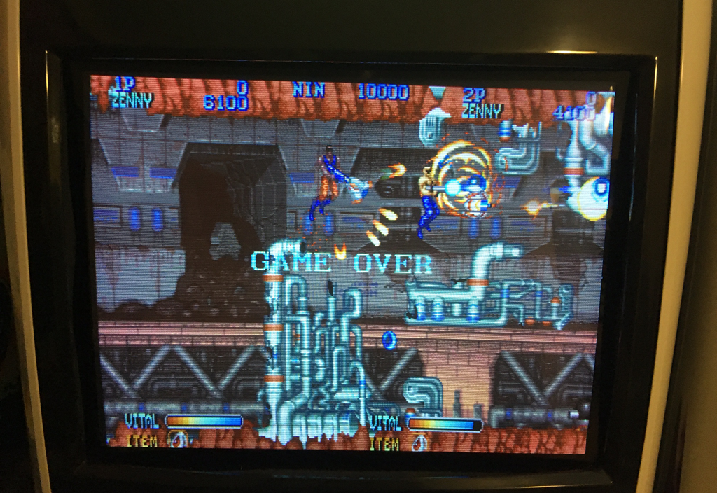
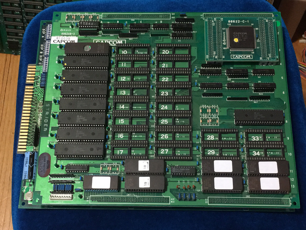
I received a CPS1 Strider for my personal collection (B and C board only) from my friend Roger this week. The board was sold as not-working, and when I fired it up, it was sure enough not working:
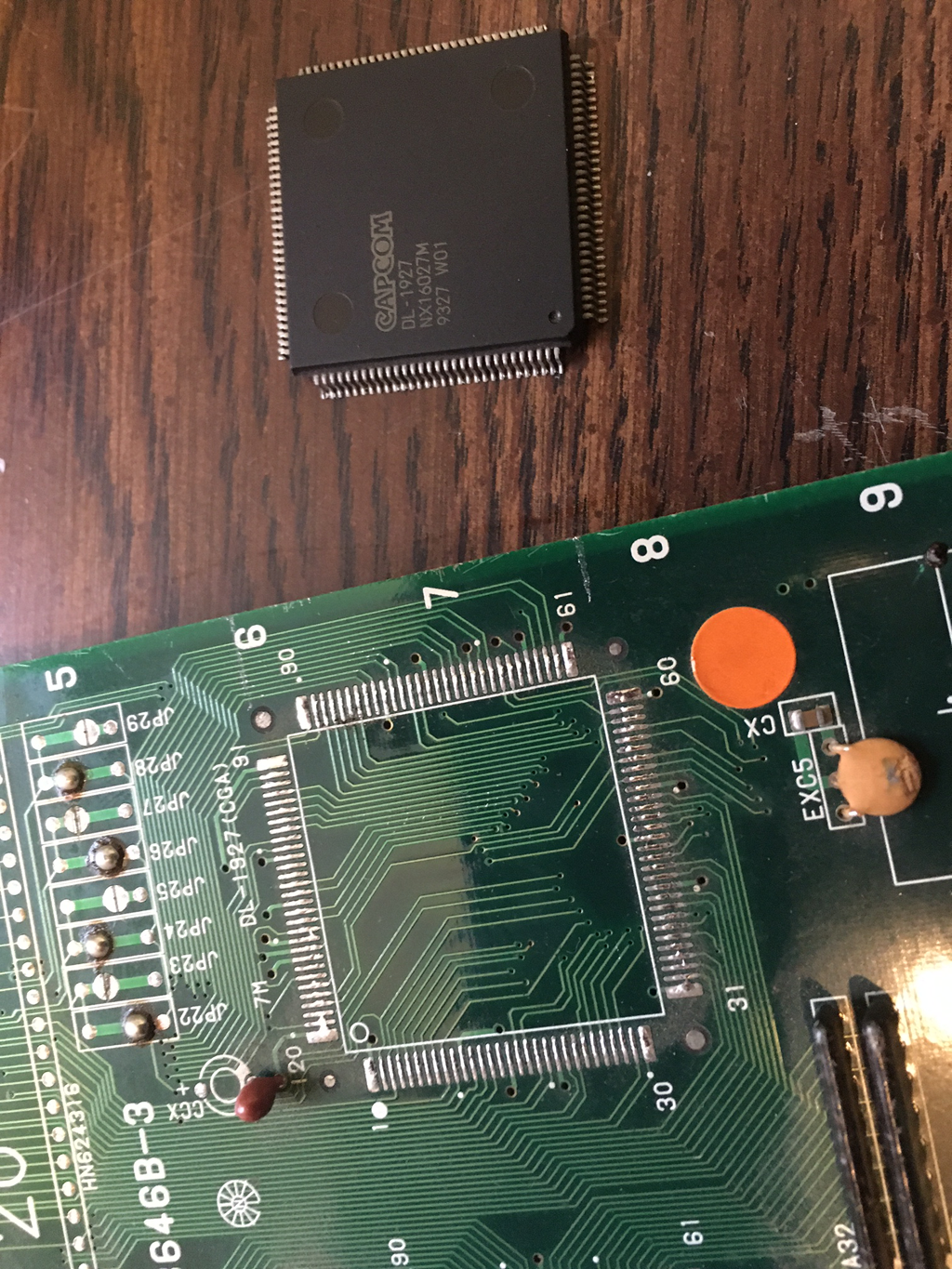
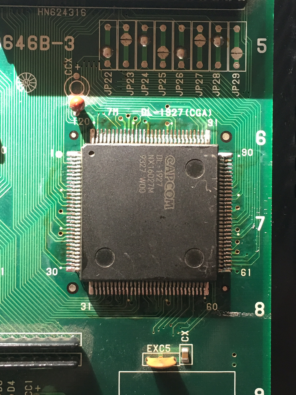
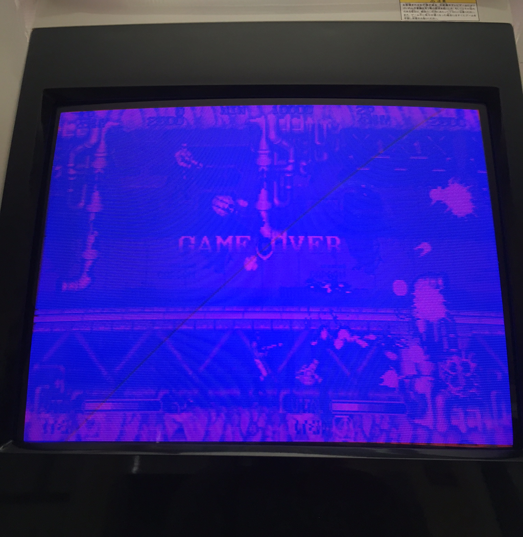
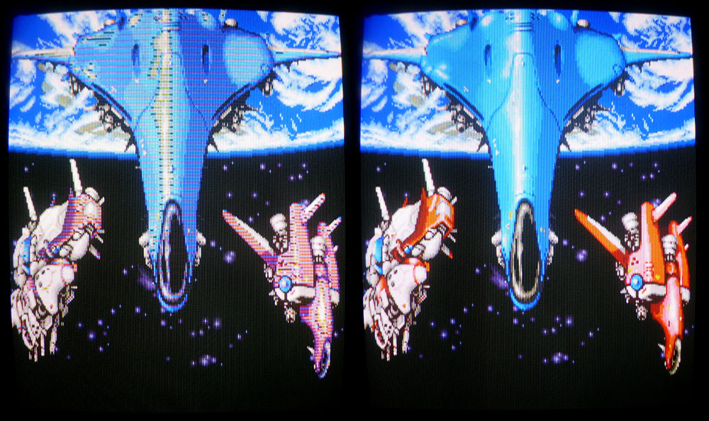
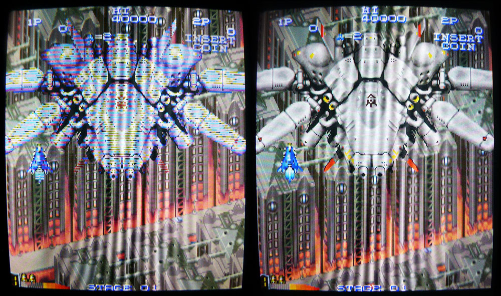
As you can see above, there were heavy jail bars present in the background sprites. Experience with CPS1 hardware told me one of three things was going on – bad C board, bad mask roms or bad/corroded sockets. The C board is the B-01 PPU variety, which is functionally equivalent to the B-21 PPU. Since I have known working B-21 boards on hand, this was an easy starting point. Swapping the board did not have any effect, so I knew it was either the mask roms or the sockets at fault.
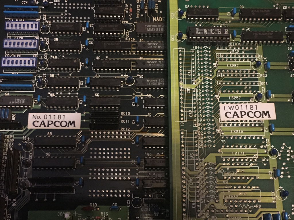
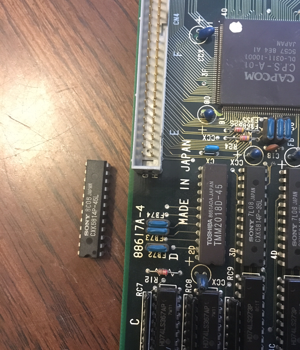
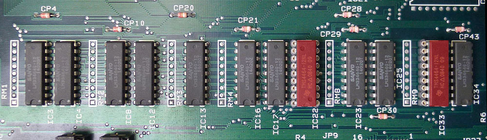
In order to verify the mask roms, I removed them from my board, and set my Superpro 580u programmer to HN27c4000g (which are pin for pin compatible the HN6204P mask roms capcom used). Strider is a very strange board in that the etched rom numbers DO NOT match with the PCB. I turned to mame source code to determine which rom file correlated to which mask rom. Sure enough, the FIRST rom I tried to verify complained about Pin 12 not having connectivity. Some times when you read mask roms as eproms, there are pins internally disconnected, and that is OK. This was not one of those times. I referenced the HN27c4000g datasheet to determine that Pin 12 was actually for Address 0. This address line is 100% required for the rom to function.
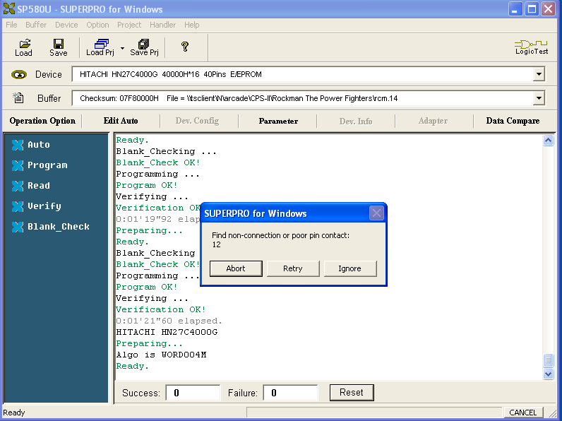
Today happened to be my lucky day. I had ONE and only ONE 27c4000g eprom on hand. Burned the mame binary to the rom, popped it in Strider, and the game was back in action!
I played a few games, did not observe any other abnormalities. I wish all repairs could be this easy! Another great Capcom game has been preserved!