Burnin’ Rubber repair log

 PCB Repair Logs  Comments Off on Burnin’ Rubber repair log
Jun 282017
 

I bought this game for my collection some months ago.


I tested briefly and it was OK. After a few weeks I decided to make a good play but the game developed a strange problem:


As you can see from the pics above, the screen was very dark and the brightness was not steady.

Also all the objects left trails of different brightness.

The problem was somewhat similar to when you don’t have video GND connected but as you can see

the text HI SCORE was repeated on top and bottom.

Adjusting the horizontal size of the image with the monitor pots ( vertical on the game) I noticed the screen didn’t shrink, it was like it had no borders.

I had immediately remembered that on the CPS1 hardware , on certain screens of some games ( 3 wonders selection screen for example)

the image is very dark and this is due to a flaw in the video circuit of the CPS1 hardware which doesn’t blank properly the video at the edges

leading to some monitor electronics to loose the black reference and behave strangely.

Charles McDonald on his website  https://www.techno-junk.org/ has a fix but right now the link is missing because he is restructuring the page.


Anyway back to the topic, I was convinced that my problem was due to video blanking not working properly, so I downloaded the Bump and Jump

schematics available from Bally (  the japanese ones are impossible to find ) and searched for a video blank signal and tested all the TTLs involved until I found this:


Output pin 5 of 74ls74@1B was floating and didn’t clear the 74LS273 connected to the video DAC


Therefore the video was not blanked properly on the edges.

Changing the TTL@1B  fixed the problem


Unfortunately after a couple of plays,  the pcb developed two other problems:

  1. Car didn’t go left
  2. car crash sound was broken


The first problem was fixed by replacing the 74LS367@4E on the sound board ( directly connected to the left direction pin)

Second problem was fixed by replacing one AY8910.

The game, for the moment, is working nicely 😉

May 252017
 

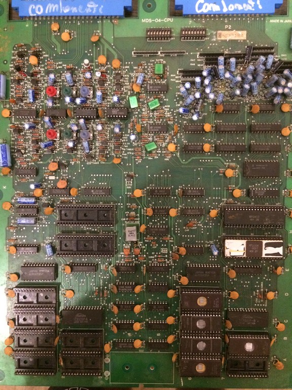
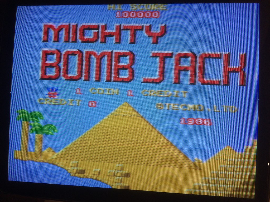
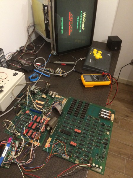
I got for my collection an untested boardset of Defender which was really in great conditions with no battery acid leak.

The boardset is the newer revision of Defender with the red label roms.

The game is very difficult to find it in working conditions nowadays because it has several weak points, expecially the 24 drams 4116 which are very unreliable to due the fact the run very hot and they require +5V, -5V and +12V to be applied at the same time, otherwise they will be damaged.

The old Williams PSU become defective and often they ruin the drams.

After converting it to Jamma and triple checked all the power supply lines I booted it up but the game appeared to be dead.

Fortunately Defender has a lot of bibliography and a very good manual which is also a troubleshooting guide.

I check the clock and it was working correctly, but after checking the reset line I saw it was pulled low all the time.

To make it short, Defender has two +12V power supplies, one regulated and one not.

You have to supply +12V also to the not regulated one because it is needed for the power on reset.

After adding that +12V t, the game booted but as soon as the message ALL UNIT OK was displayed it reset in a never ending loop.

I found out that the problem was caused by the ribbon cable , after reseating it a couple of times, the game booted correctly.

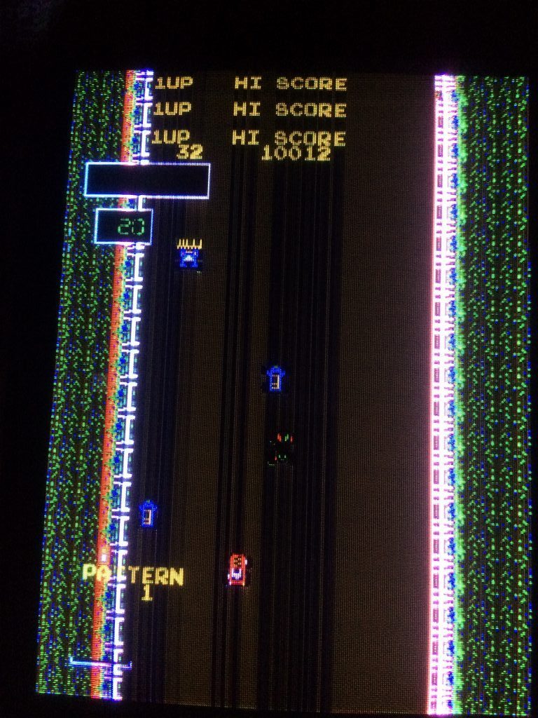
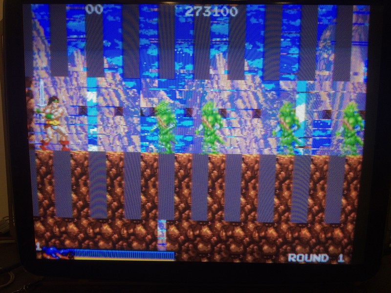
I started the game but the ship kept always going down.

With the test menu , it reported that the down direction was always pushed.

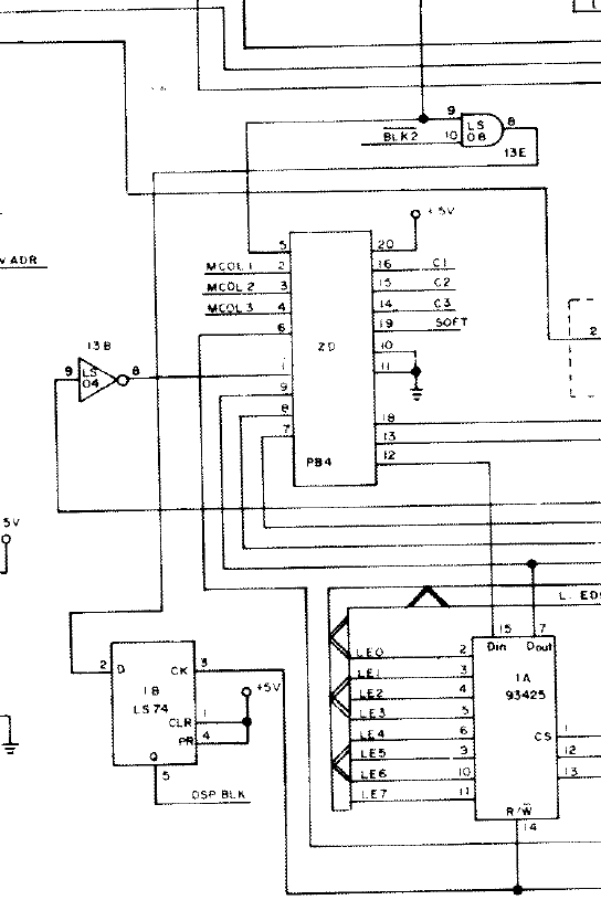
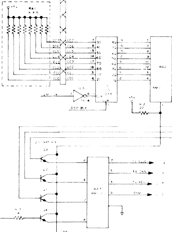
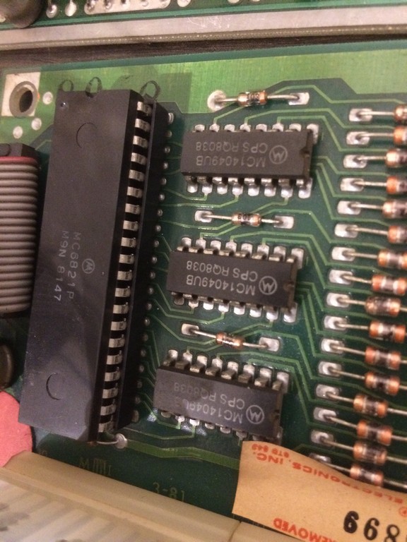
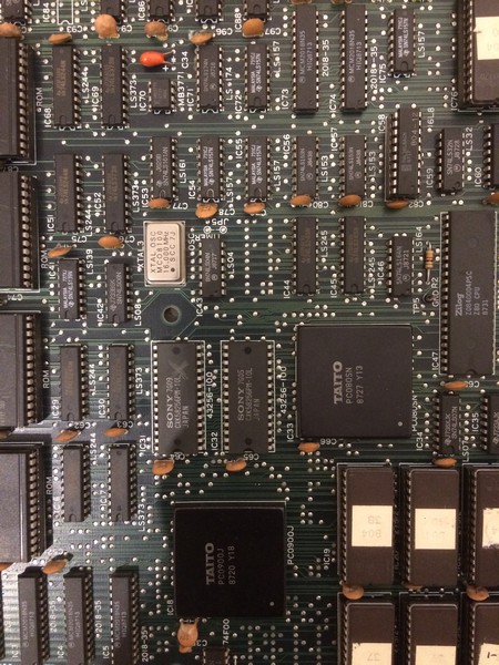
I checked the interface board which has the circuit for the inputs. the hex inverters 4049 were all toggling correctly, the pull up resistors were good therefore there was only one chip to check: the Peripheral Interface adapter 6821P.

I desoldered it and installed another one I had on stock taken from another arcade games.

Since I had no way to test it, I decided to put a 40 pin socket just to be sure I could easily swap it with another one in case it was defective.

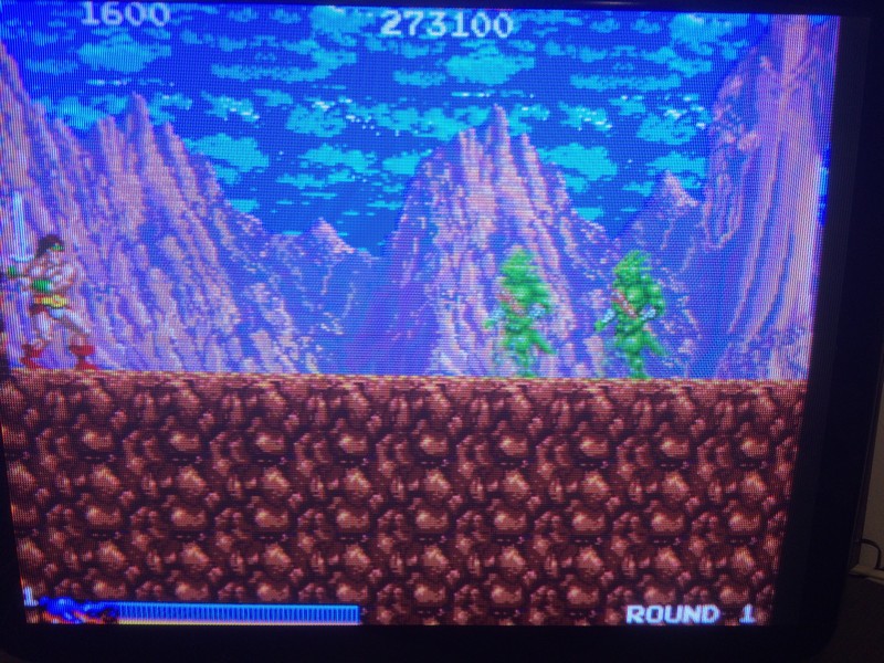
Luckily the inputs were now correct, thefore I could declare the board fixed.

In the end I was very lucky because the game had only the input problem and no other issues.


Rastan repair log #5

 PCB Repair Logs, Repair Logs  Comments Off on Rastan repair log #5
May 252017
 

The game had some missing background tiles


At first I thought it was a maskrom problem but once I checked all of them only to find they were good, I started to probe the ram responsible for the background.

A sram @IC31 had some weak data signals so I decided to change it and the guess was right because the game was fixed.

Michael Jackson’s MoonWalker repair log #1

 PCB Repair Logs  Comments Off on Michael Jackson’s MoonWalker repair log #1
May 212017
 

Another board from the recent operator raid, an original Michael Jackson’s MoonWalker (on Sega System 18 hardware)

Despite its age and the use of the FD1094 CPU module with battery backed-up RAM the board was still working except for the sound samples (drums, speeches, etc..), they were missing or replaced by random ones:

The hardware uses a rebranded Ricoh RF5C68 as PCM sound chip :

Not able to find any datasheet I went to “listen” its pins with an audio probe.When I hit the analog outputs (the IC has an on-board DAC) I realized that sound came already wrong out of it.So the chip was the only responsible and it needed to be replaced:

Done and…success!Board completely fixed.

 Posted by at 9:50 pm

Asterix repair log #1

 PCB Repair Logs  Comments Off on Asterix repair log #1
May 212017
 

Another Konami PCB on the bench!

Picked-up this Asterix PCB in a recent operatot raid:

Board was physically damaged, one part of PCB was litterally missing and the nearby 16Mbit MASK ROM was cracked in half:

The affected part was not a vital section of circuit (but only a spare room for not used additional MASK ROMs) so board still booted but sprites were missing.If I pressed the ‘053245’ ASIC they came back but garbled and blocky:

For first I reflowed some bent pins of the ‘053245’ sprites generator:

Then I replaced the broken 16Mbit MAS ROM @3K with a compatible 27C160 :

This improved things but not still perfect :

The MASK ROMs check complained about the other device containing sprites data (the one @7K)

Like said in my previous Parodius DA! repar log, this doesn’t necessarily imply that IC is faulty but also that it cannot be reached  by the device which wants to read/write it.Address bus is shared among the two MASK ROMs @3K and 7K, doing a check with my muktimeter all was fine except for pin 42 of both, I got no continuity between them :

Pin 42 is the higher address line:

I simply ran a jumper wire, this restored sprites and fixed completely the board:

 Posted by at 7:05 pm