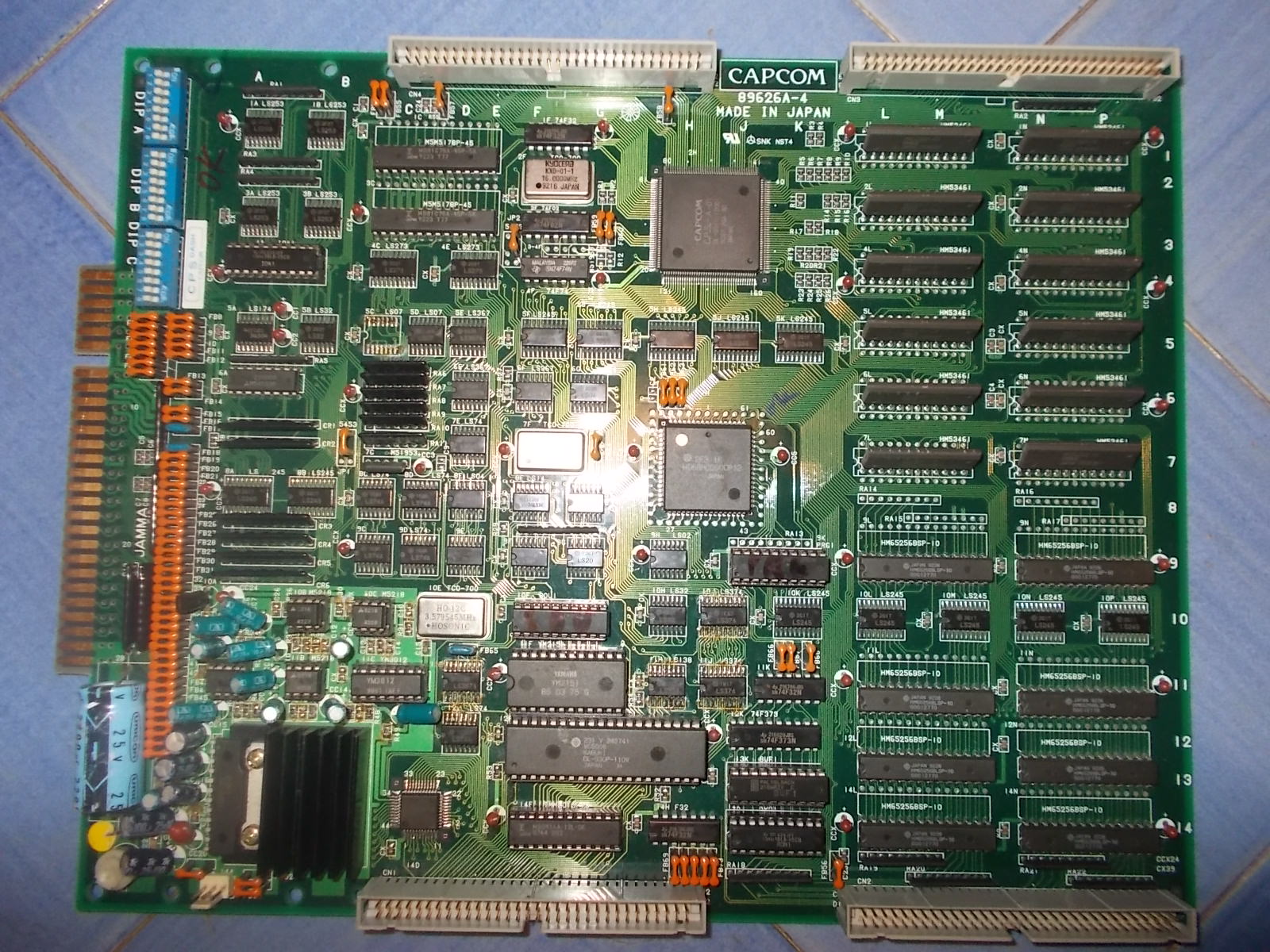
Received this quite rare Hard Puncher (on Konami Twin16 hardware) for repair:
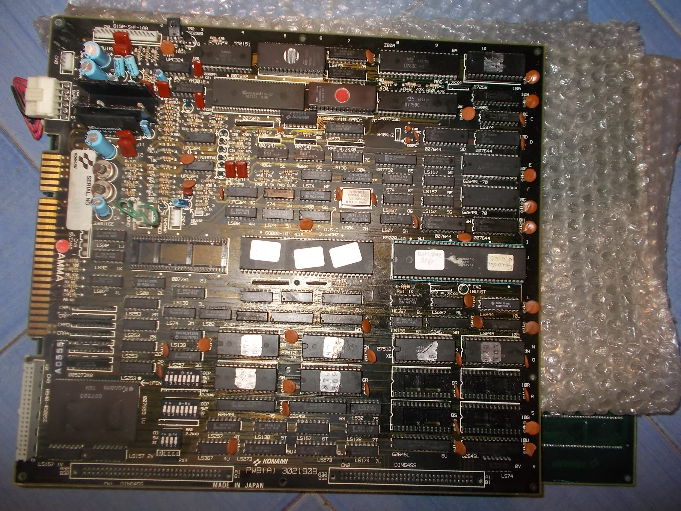
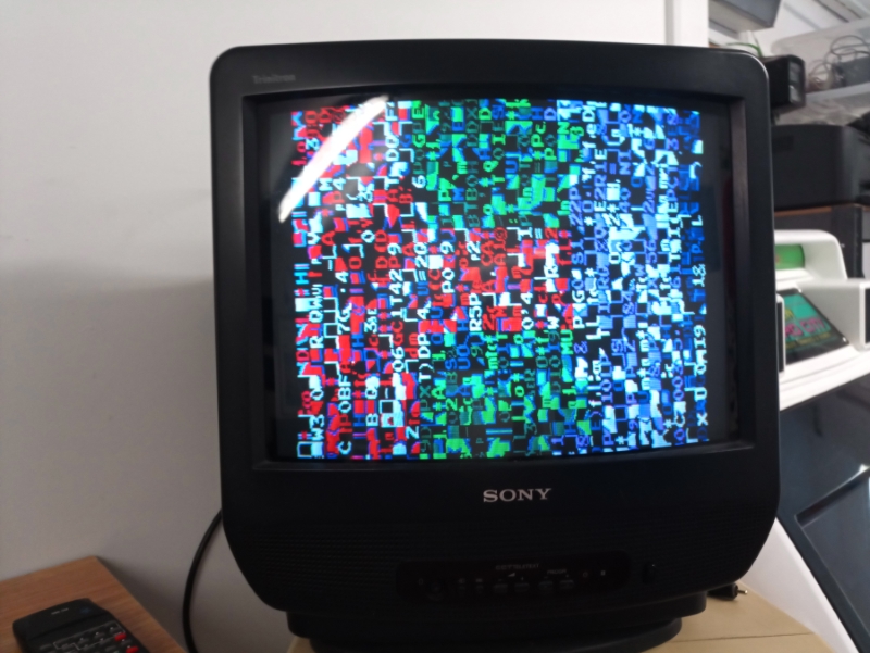
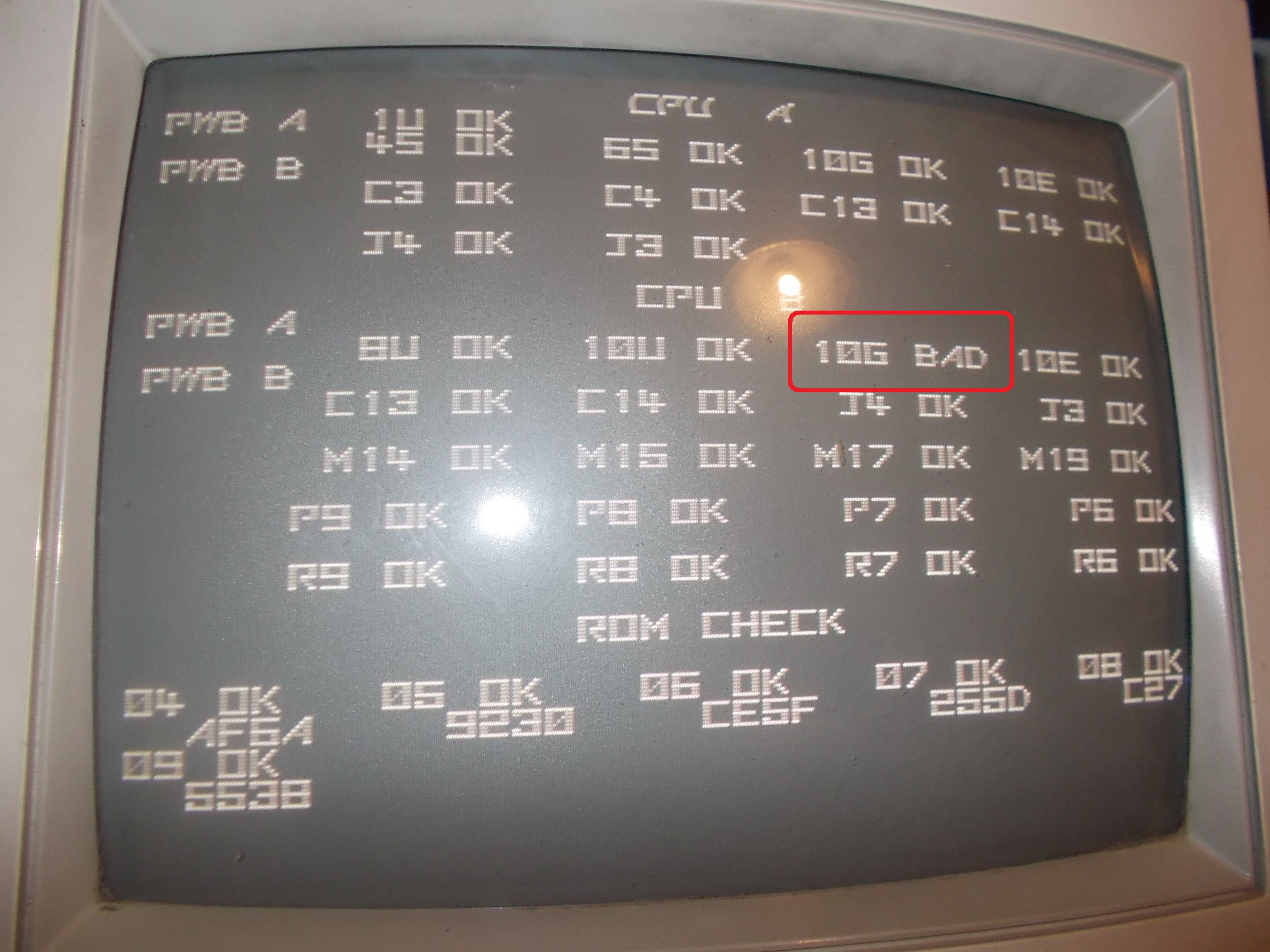
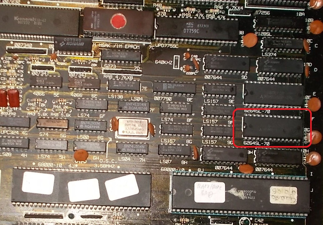
PCB failed all the time the self-test showing a bad device @10G on CPU board and then resetted, this in an endless loop:
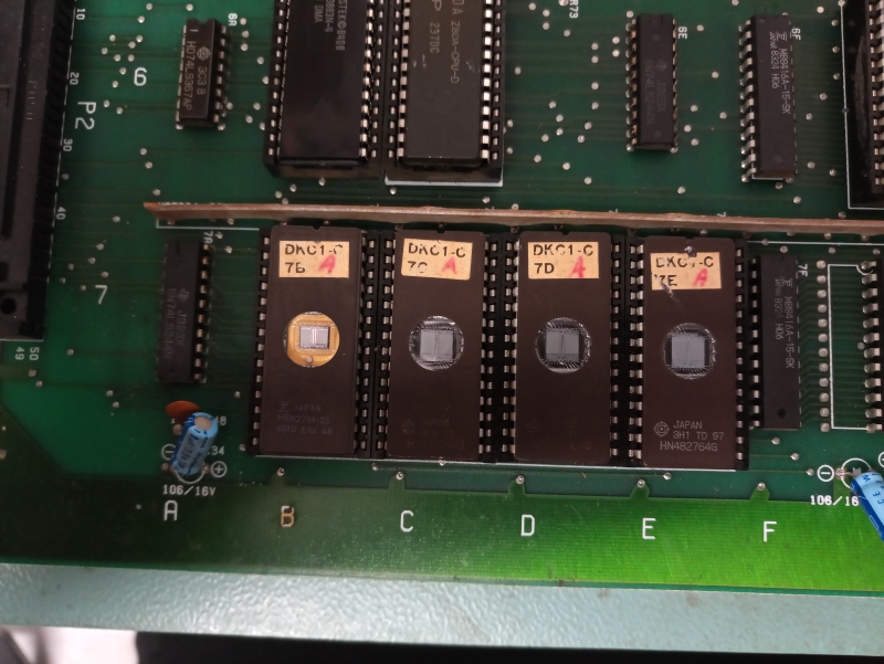
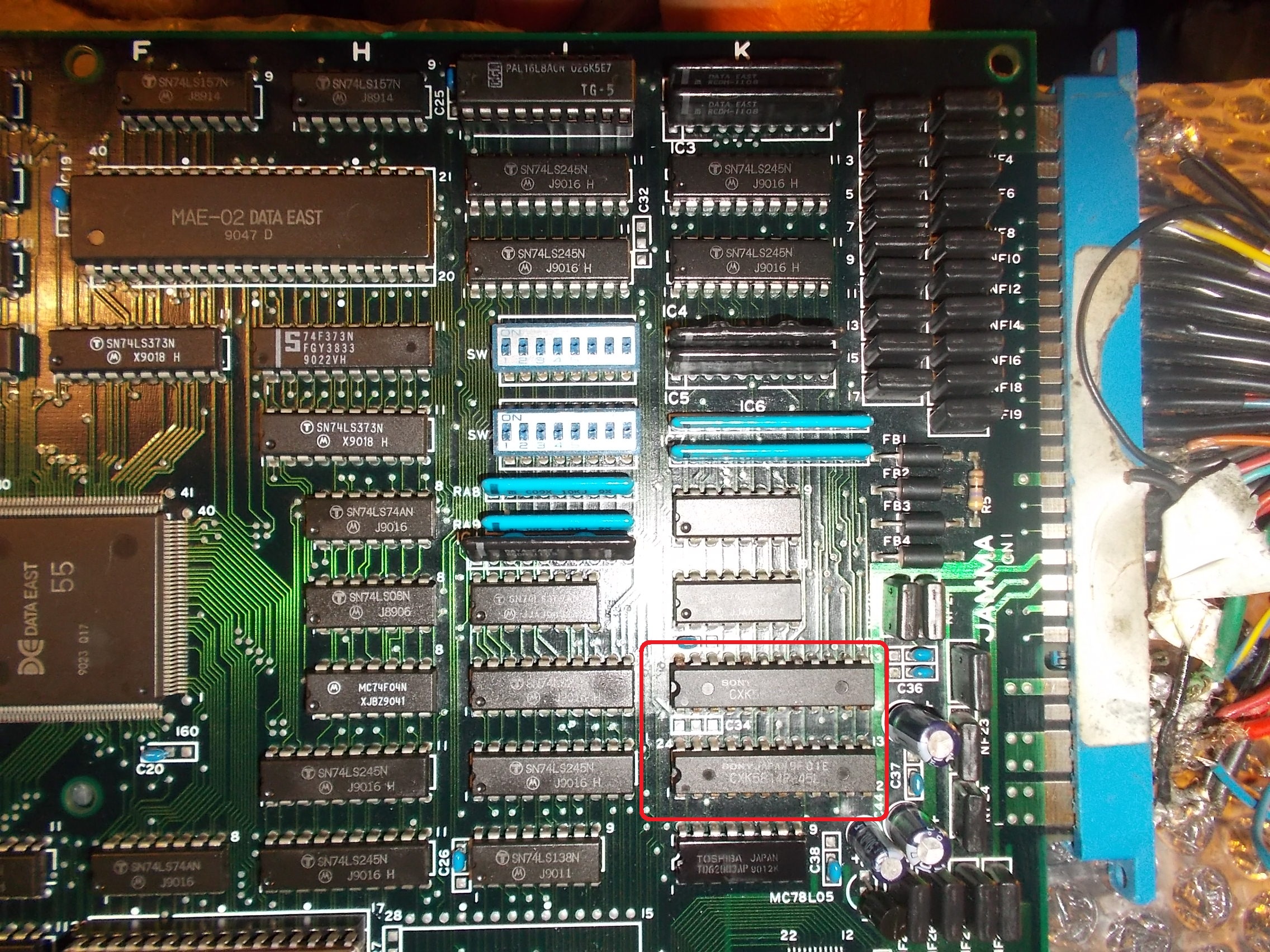
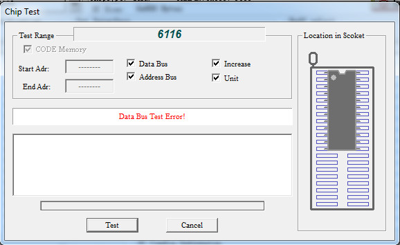
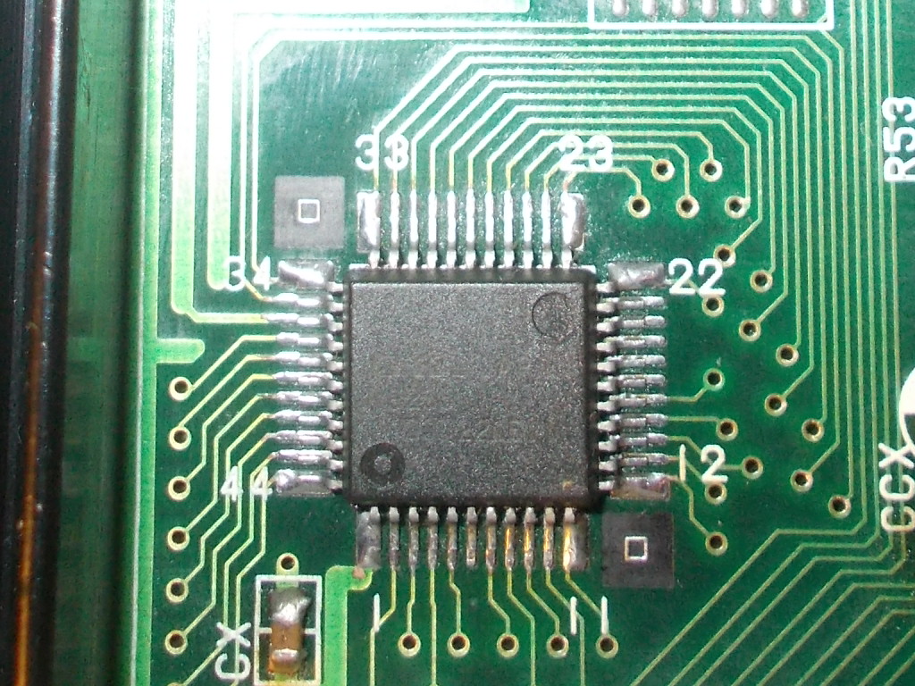
The involved device is a Mitsubishi M5M5165 (8K x 8-bit static RAM) compatible with 6264 :
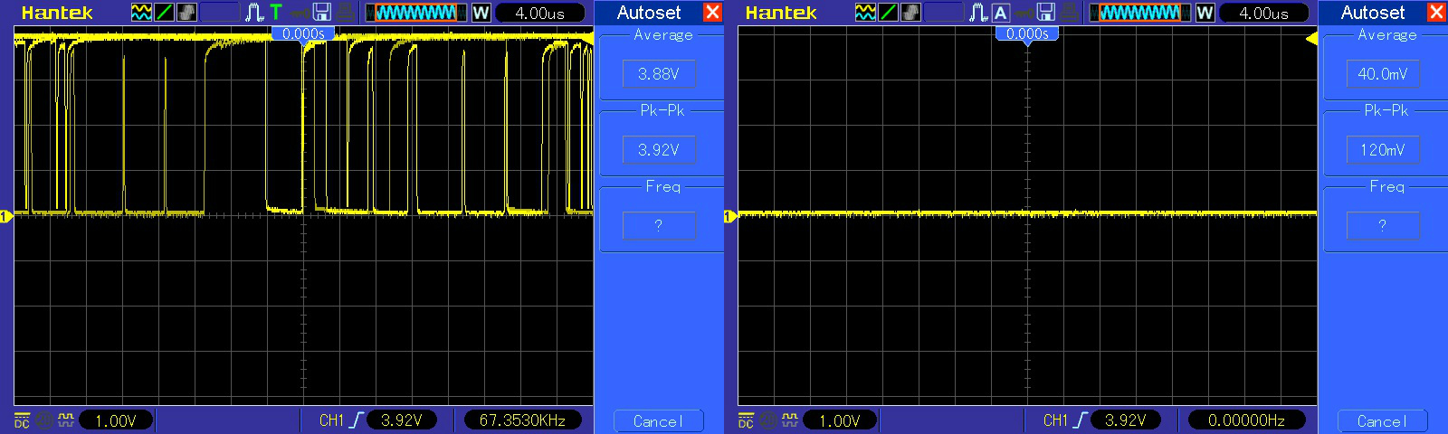
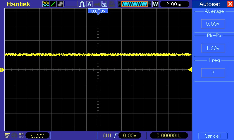
Its data bus showed no activity:
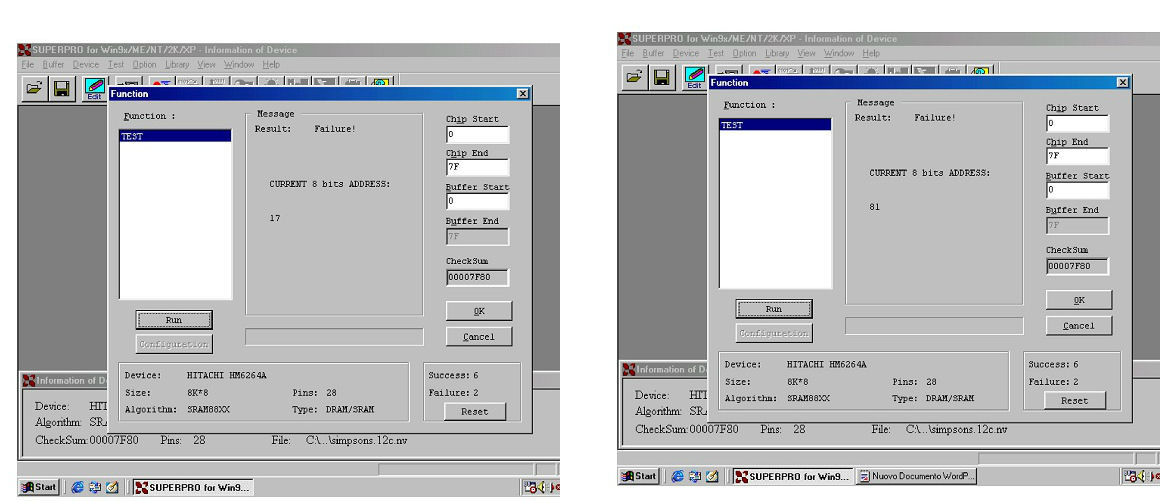
The chip failed the out-of-circuit test each time in a different address location:
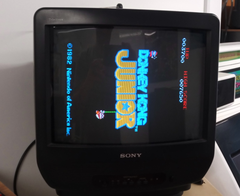
With a good RAM the board successfully booted into game:
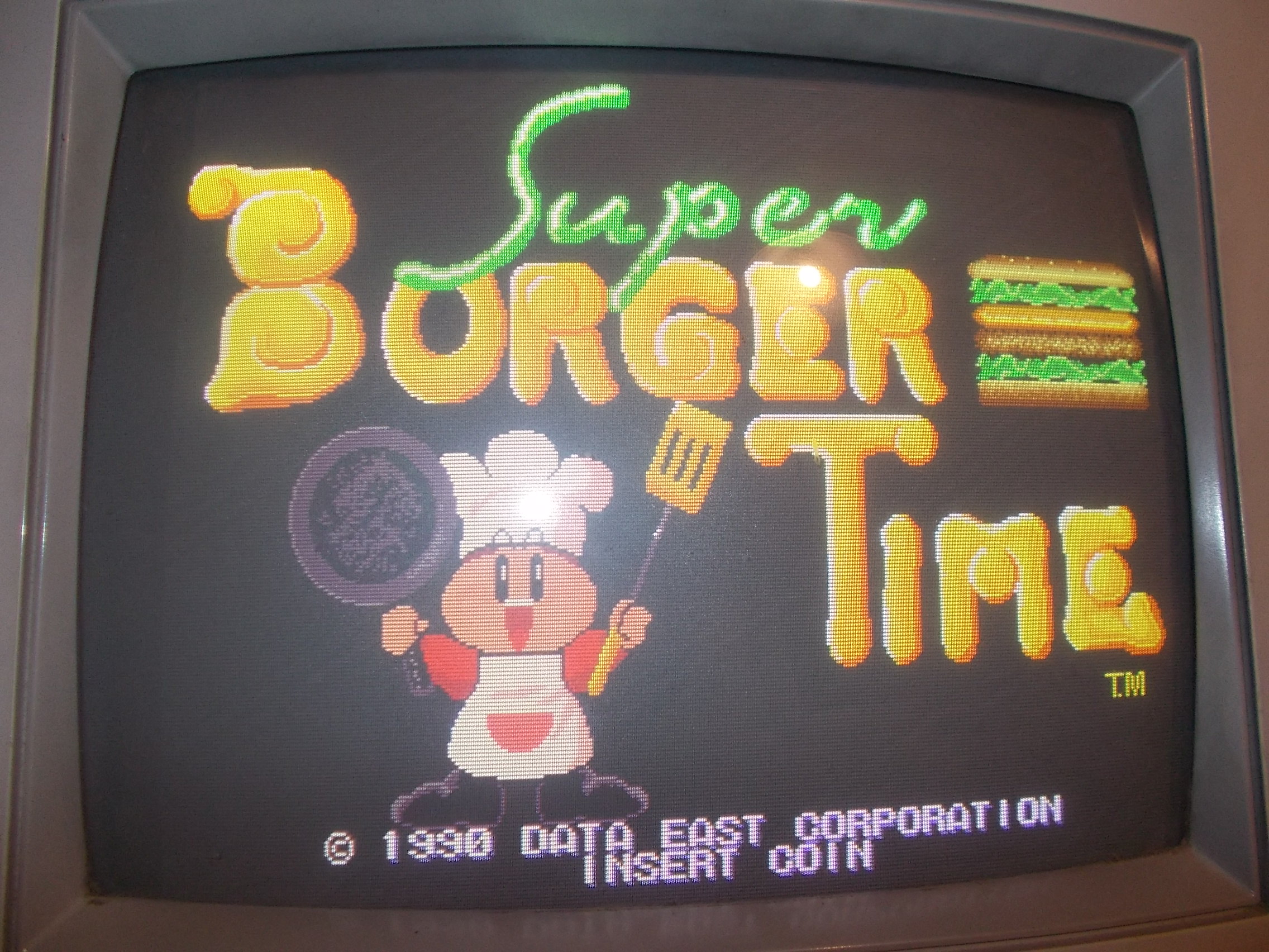
But speeches were missing, here is a comparison with a MAME recording:
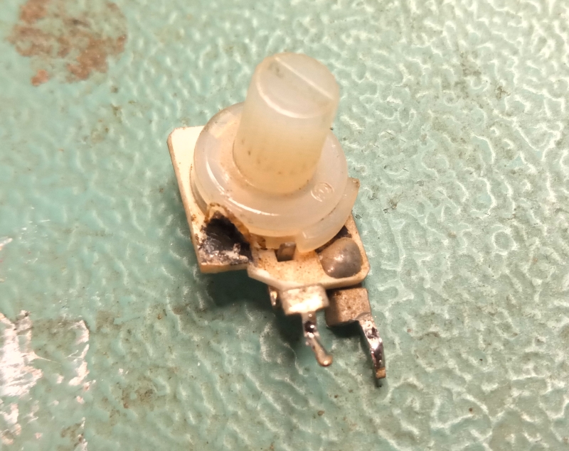
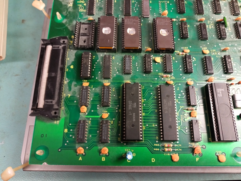
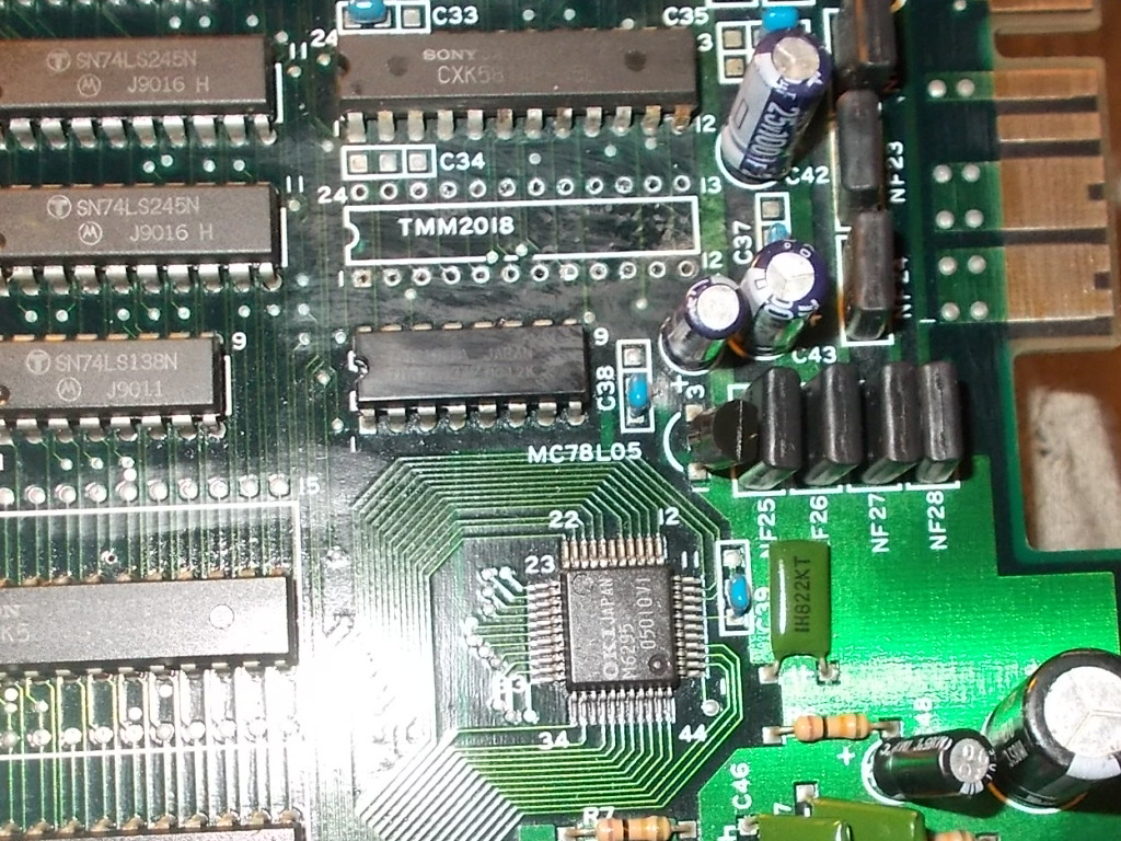
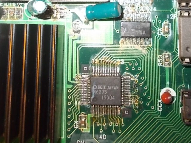
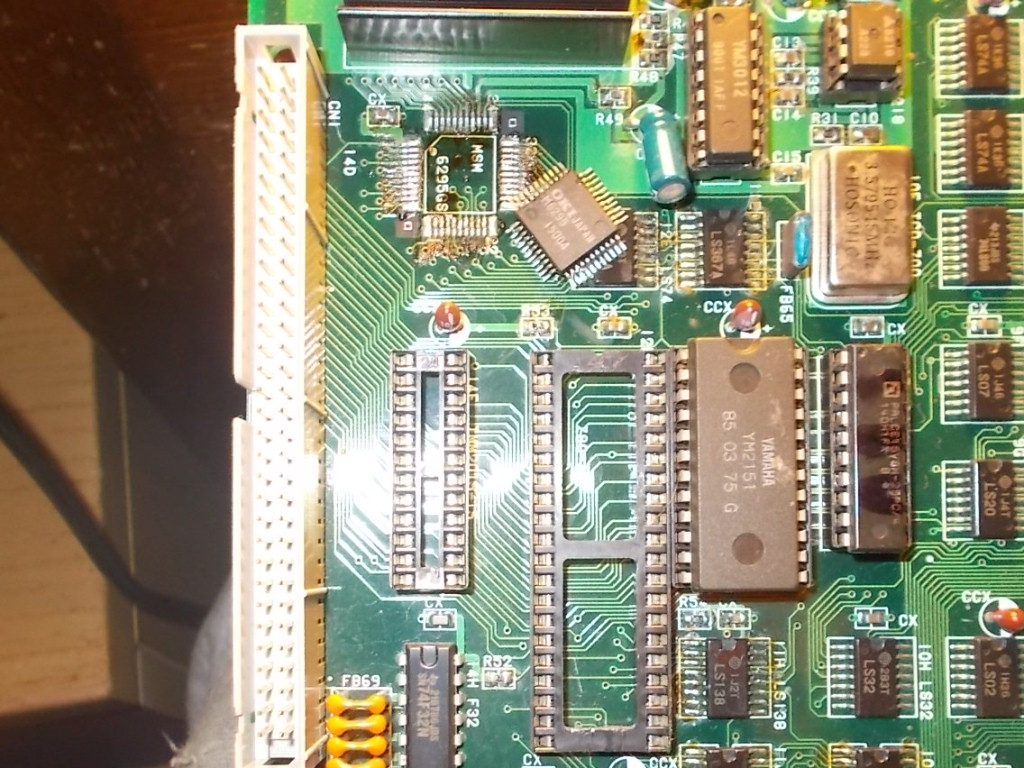
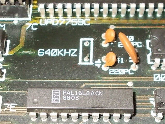
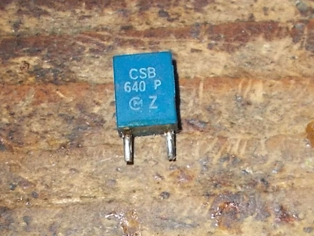
I quickly pinpointed this fault in a missing 640KHz ceramic resonator, this is for generating clock to the uPD7759 ADPCM speech synthesizer IC.I took a spare from a dead Sega System16B motherboard:
Job done.