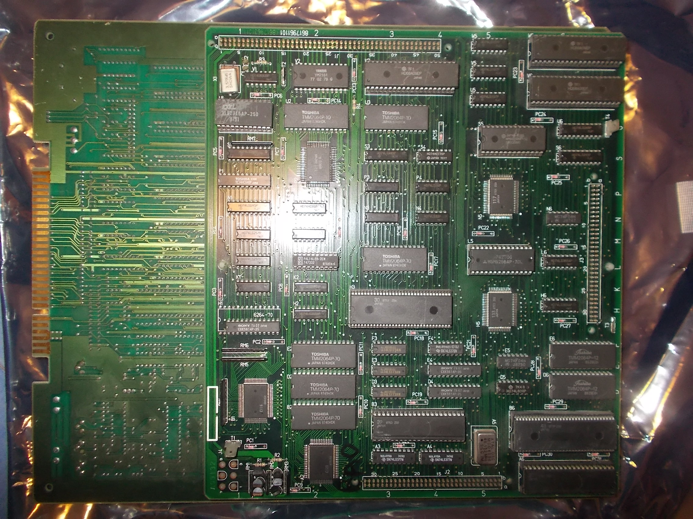
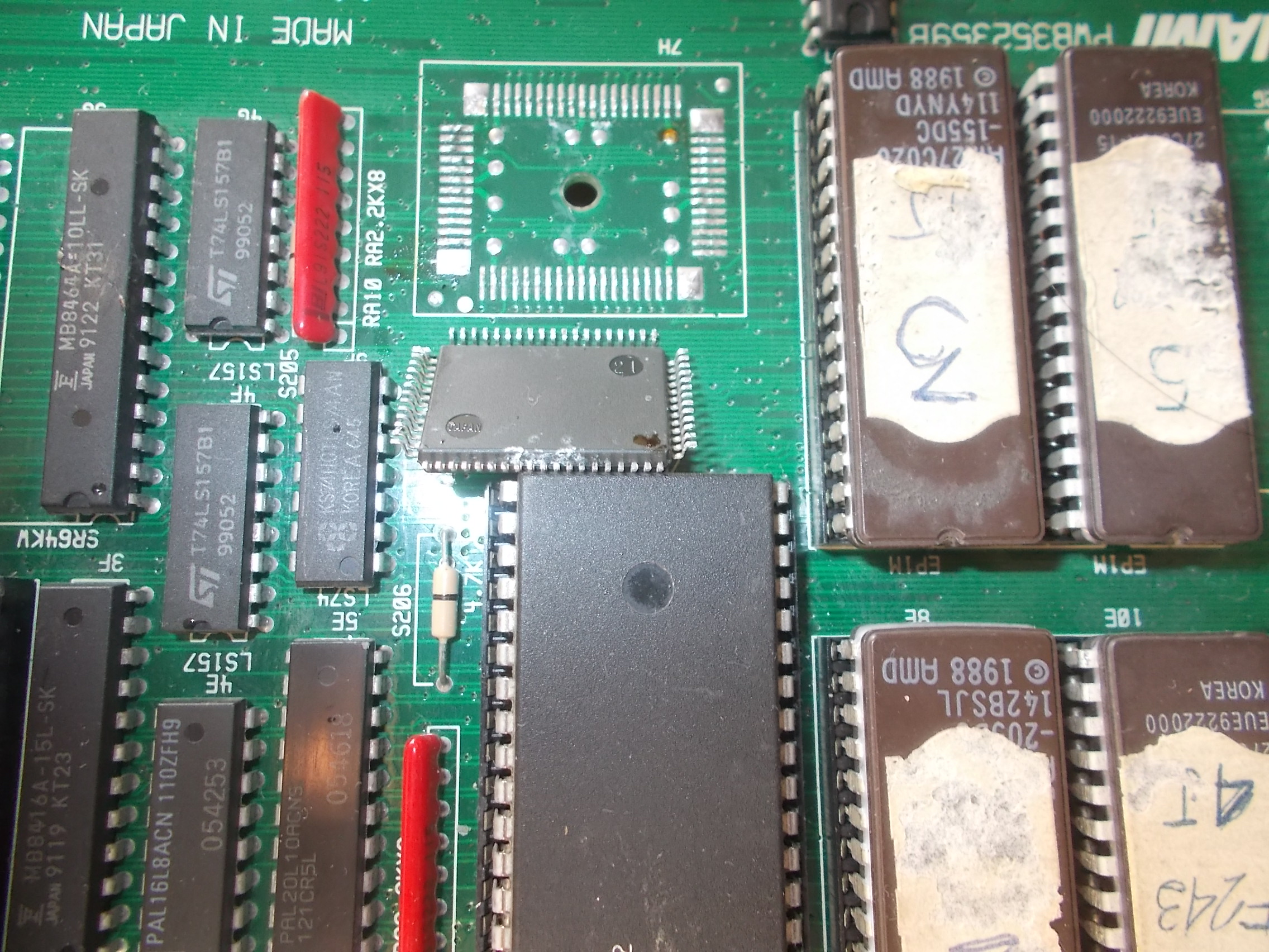
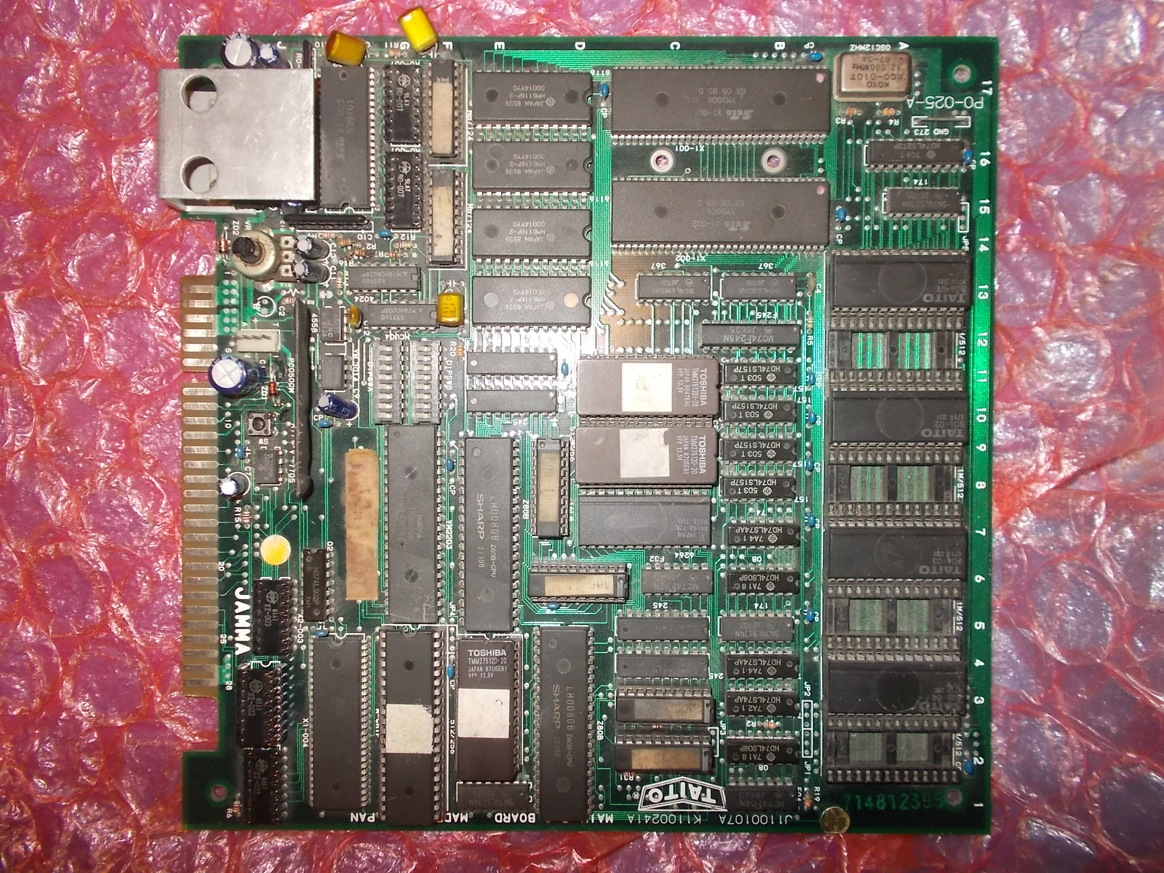
Some time ago I bought a lot of original faulty boards, there was among them a Taito PCB which at first gance I could not identify:
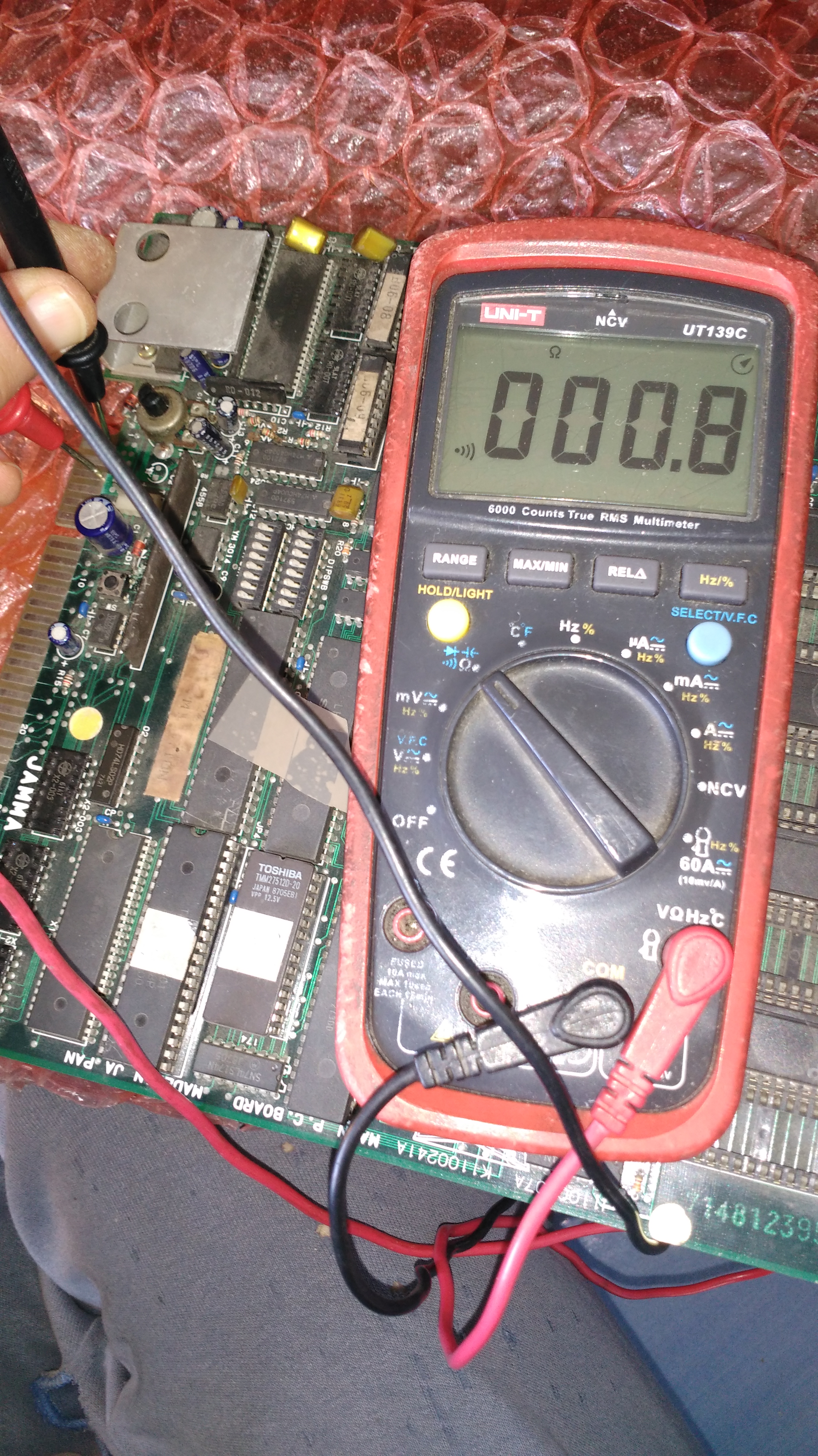
I could not power it up because there was a dead short between GROUND and +5V :
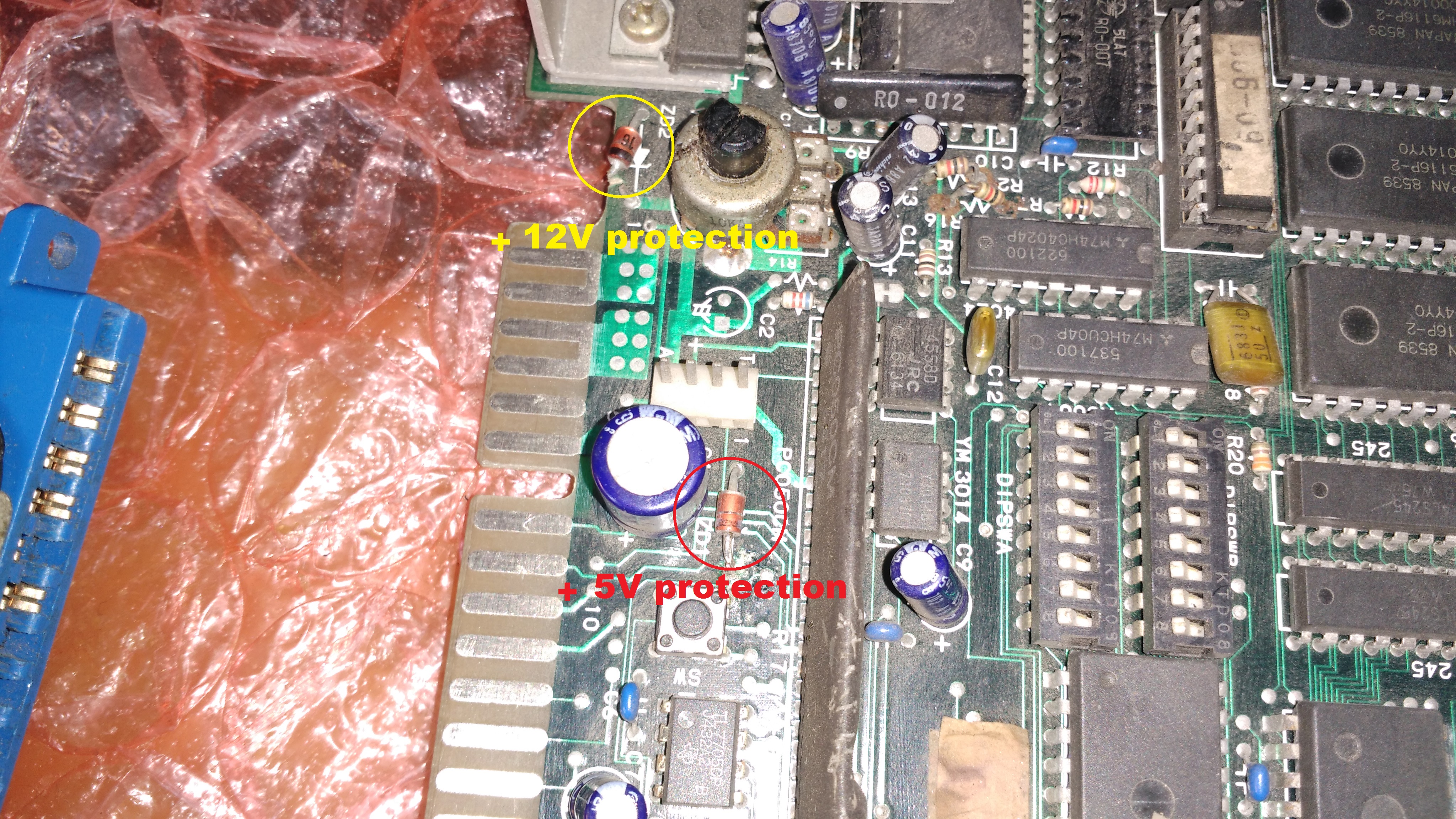
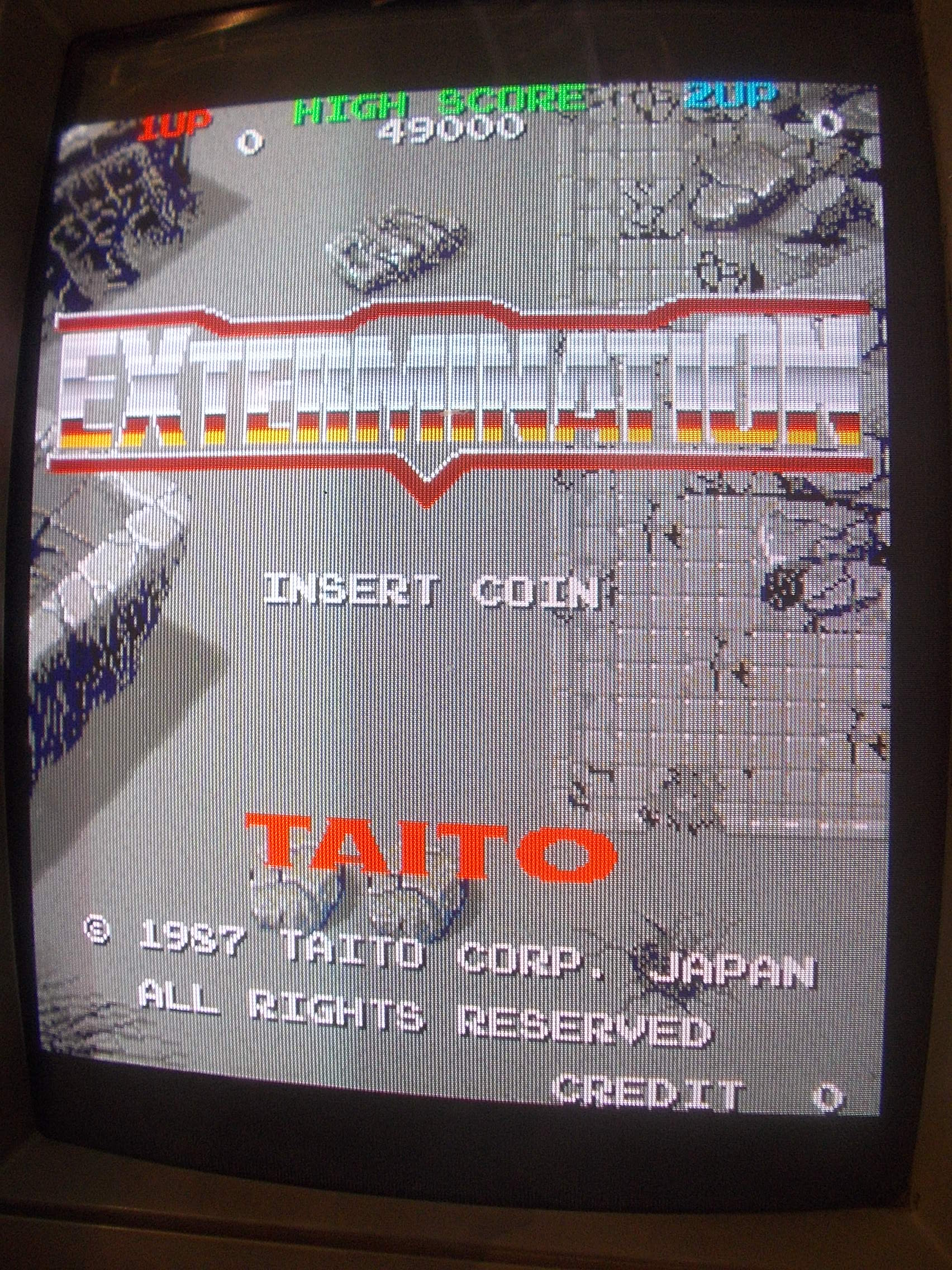
So I dumped some ROMs and it turned out to be Extermination, a vertical shoot’em up game (that runs on “The New Zealand Story” hardware) released by Taito in 1987.Someone previously tried to troubleshoot the board and cut one terminal of a zener diode thinking it was shorted but this was for +12V line protection whereas there is another zener diode to protect +5V which was actually bad causing the short to GROUND:
Once replaced the zener diode and cleared the short I powered the board up and it booted into game but sound was missing and colors were wrong with a dominant blue :
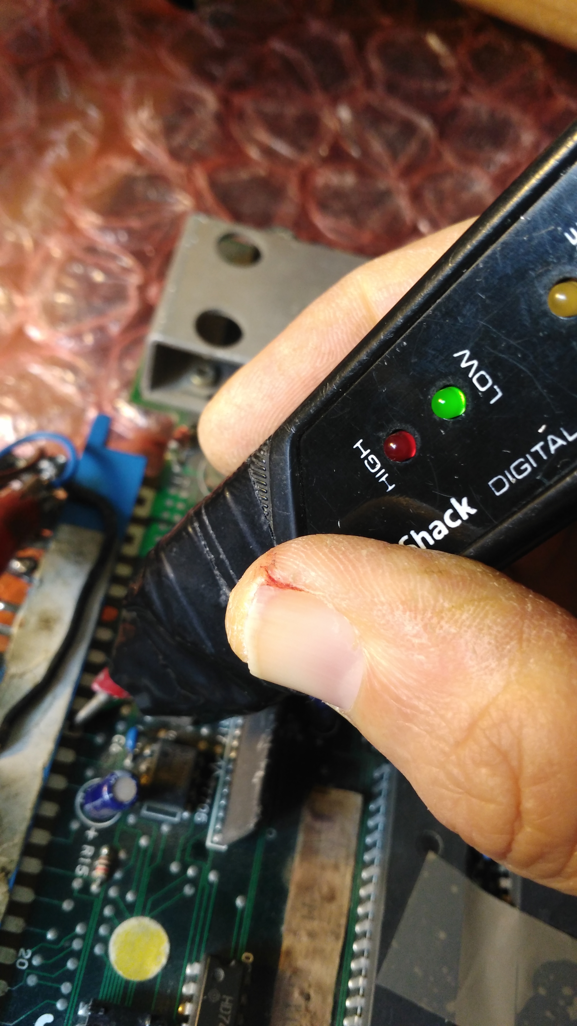
A blueish image means the RED color is missing or has some troubles.This was confirmed by the logic probe, the signal was indeed stuck low :
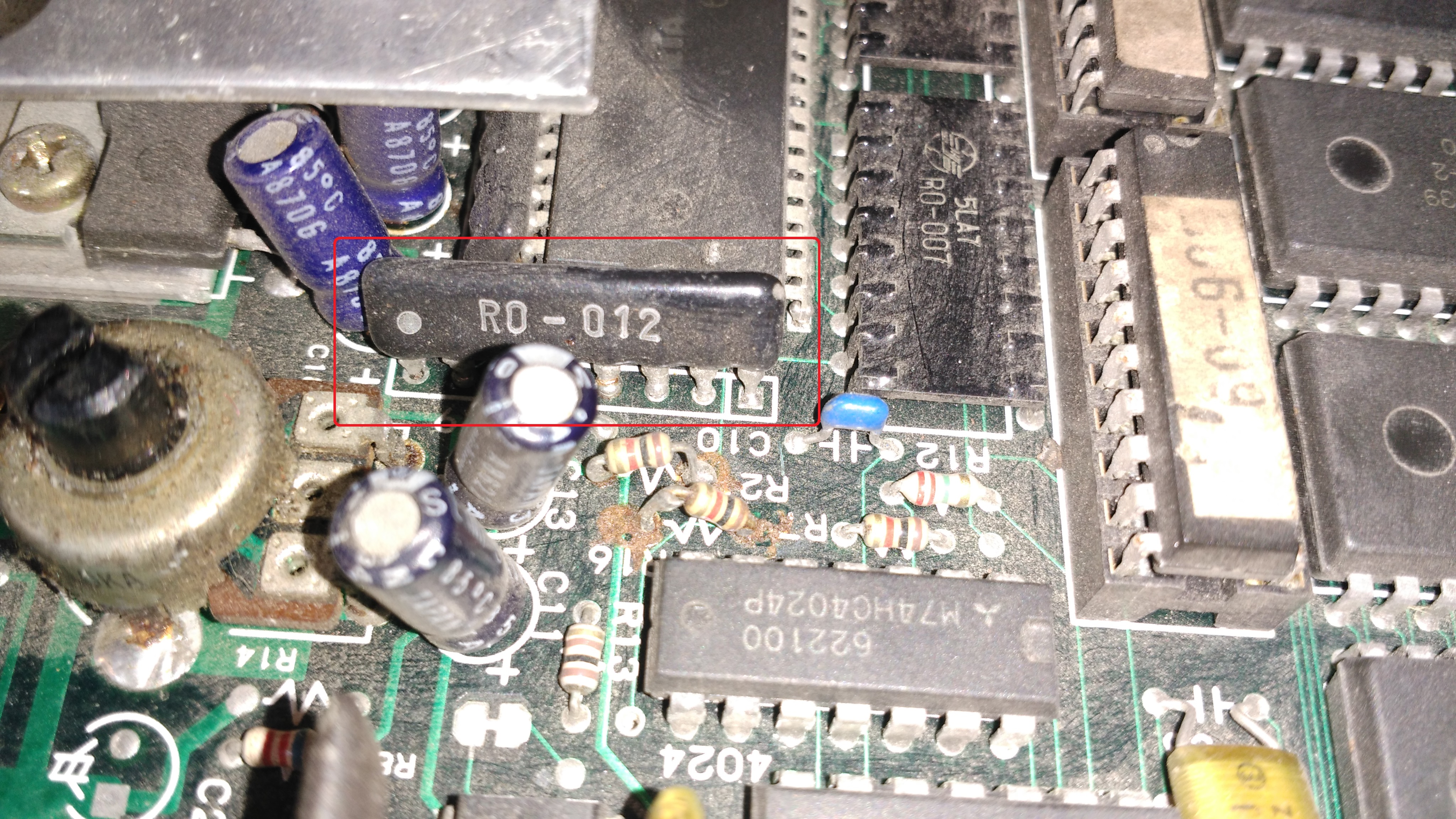
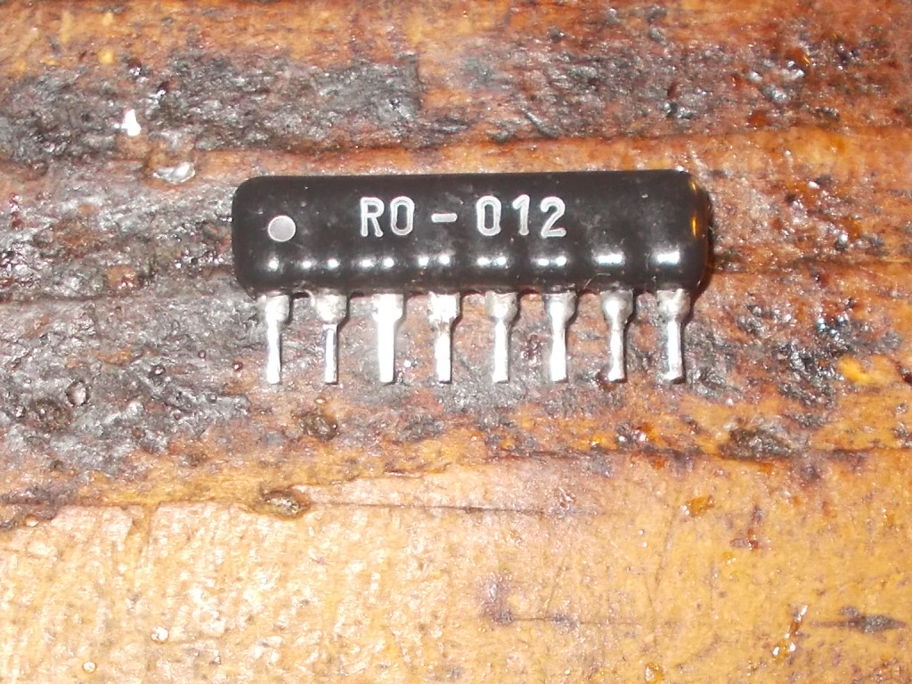
I could trace the JAMMA edge connector pin of RED back to a SIL component marked ‘RO-012’, a typical R/2R resistor ladder used as RGB DAC (one for each color).A closer inspection revealed the part was mounted backwards:
Reinstalling it with right orientation restored the RED color but image was now purplish :

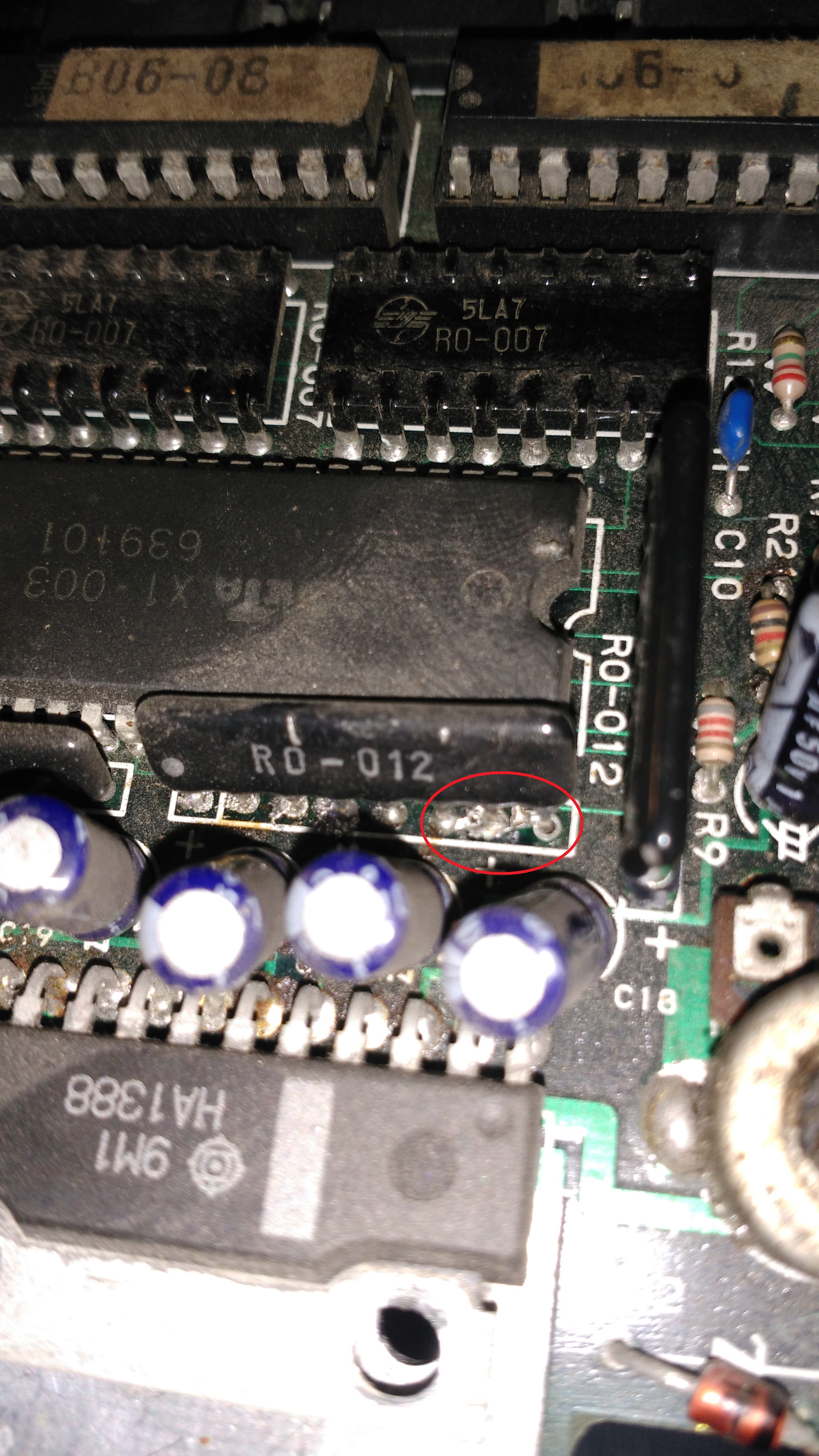
This meant the GREEN color had some troubles.I located the relevant ‘RO-012’ DAC near the sound amplifier and found that some pins were shorted by a solder bridge:
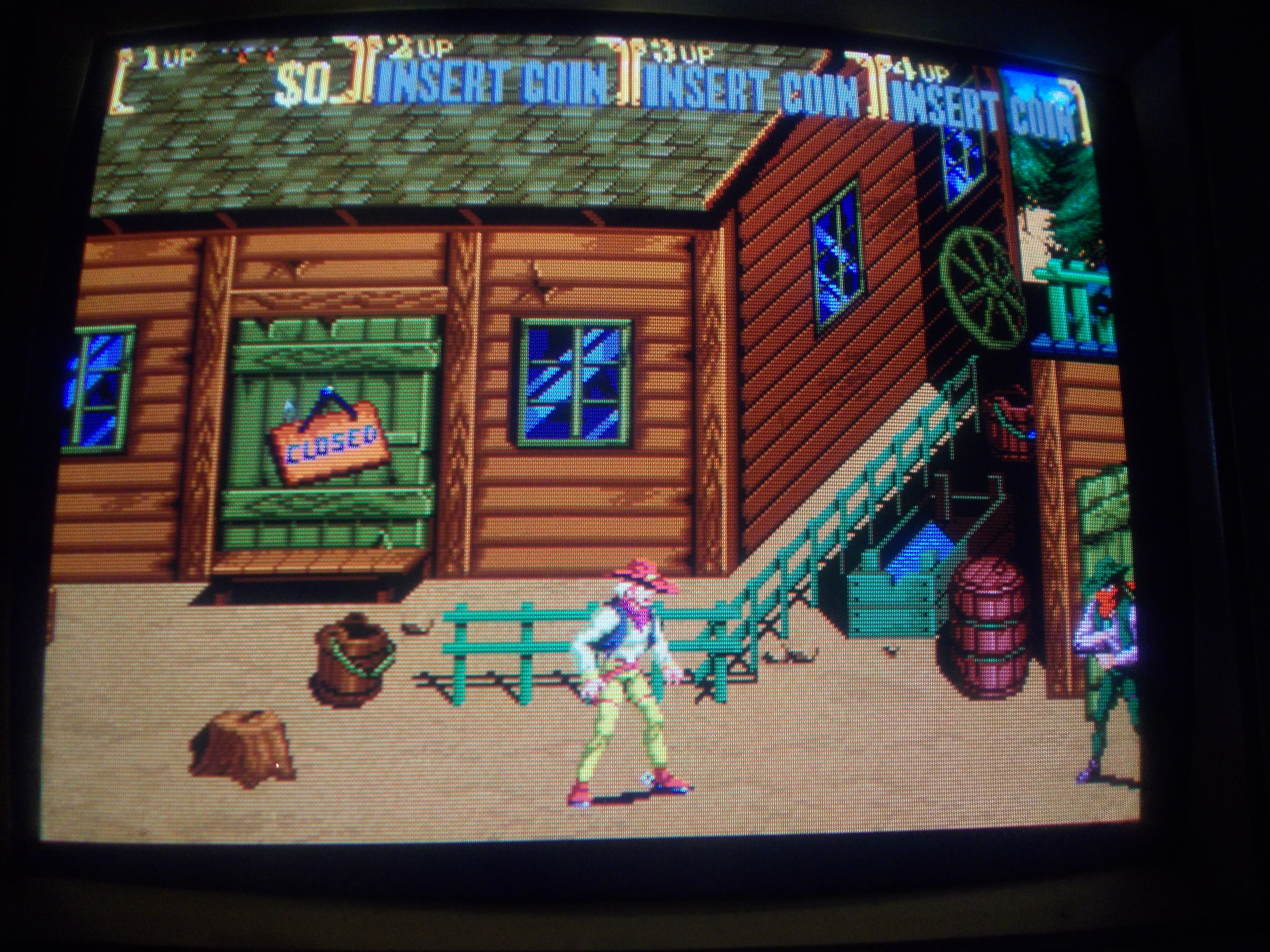
Removing the bridge finally restored the correct colors :
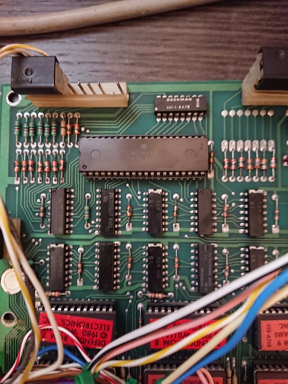
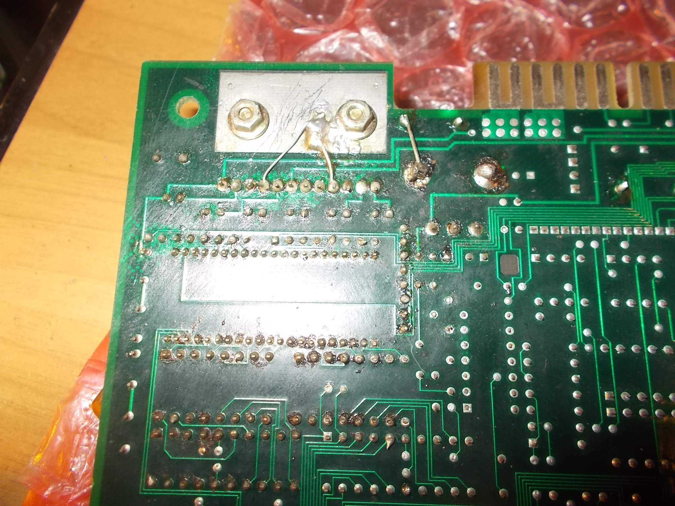
Now the lack of audio.From signs on solder side I noticed someone previously reworked the sound section replacing the amplifier (an Hitachi HA1388) and potentiometer (and perhaps also capacitors)
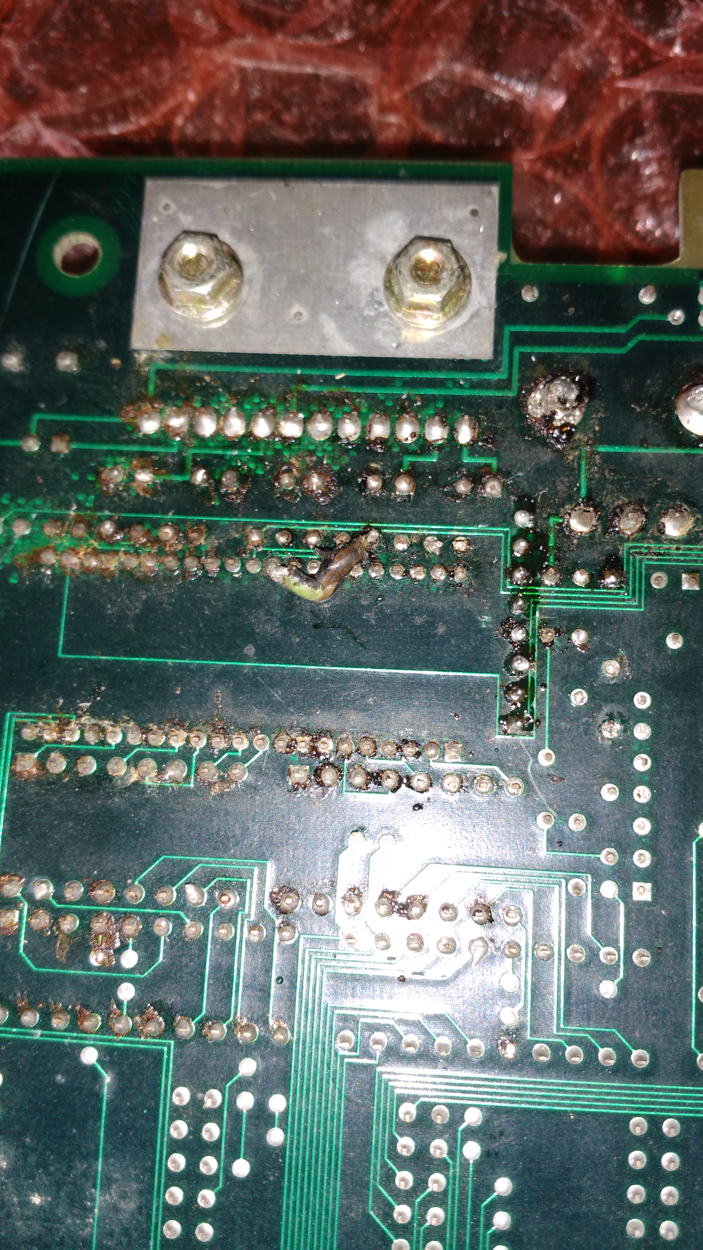
Checking the +12V confirmed this voltage was present on board but not on amplifier when I put the black probe of my multimeter on the two GROUND pins of the HA1388 (pin 4 and 9).At the end it turned out that who replaced the amplifier and potentiometer managed to lose their GROUND connection likely ripping off the rivets from the holes (power pins are always harder to desolder due to presence of internal planes).I restored the connections in this way :
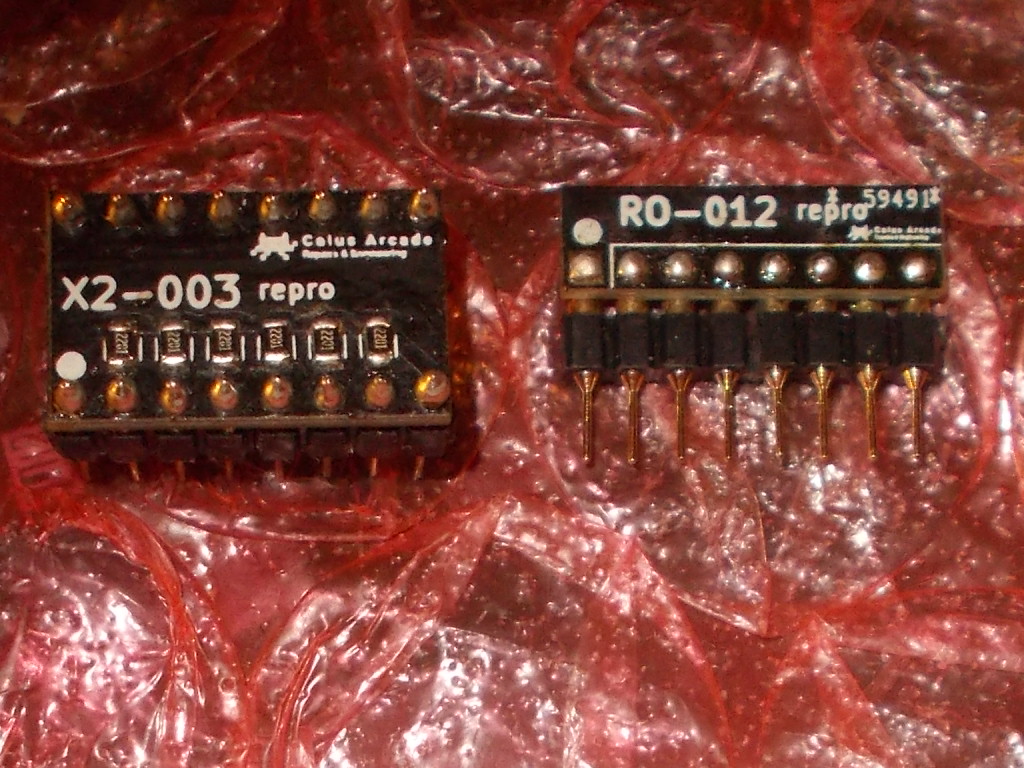
Sound was back again.Board 100% fixed and job done.Before archiving this repair I took the chance to see if some parts (simple ones, not digital ASICs) were worth to be reproduced.I chose the aforementioned ‘RO-012’:
And the ‘X2-003’ :
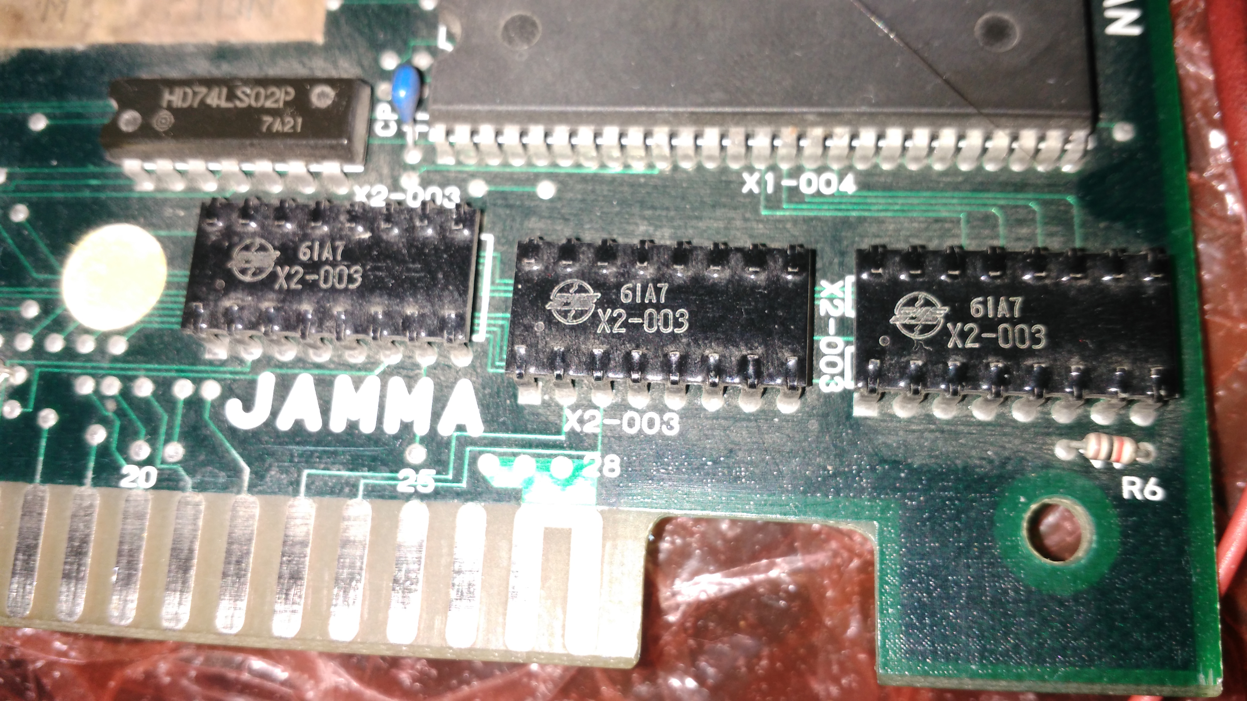
The first, as said above, is an R/2R resistor ladder acting as RGB DAC, the latter is a capacitors/resistors array used for inputs but, unlike all the others, comes in a DIP16 ceramic package hence quite fragile.Reproducing them was straightforward :