Jul 192013
 

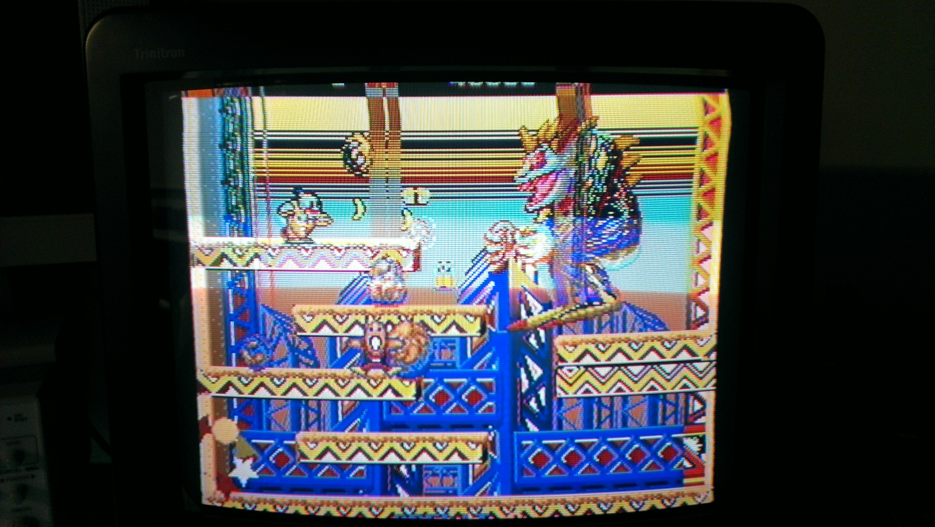
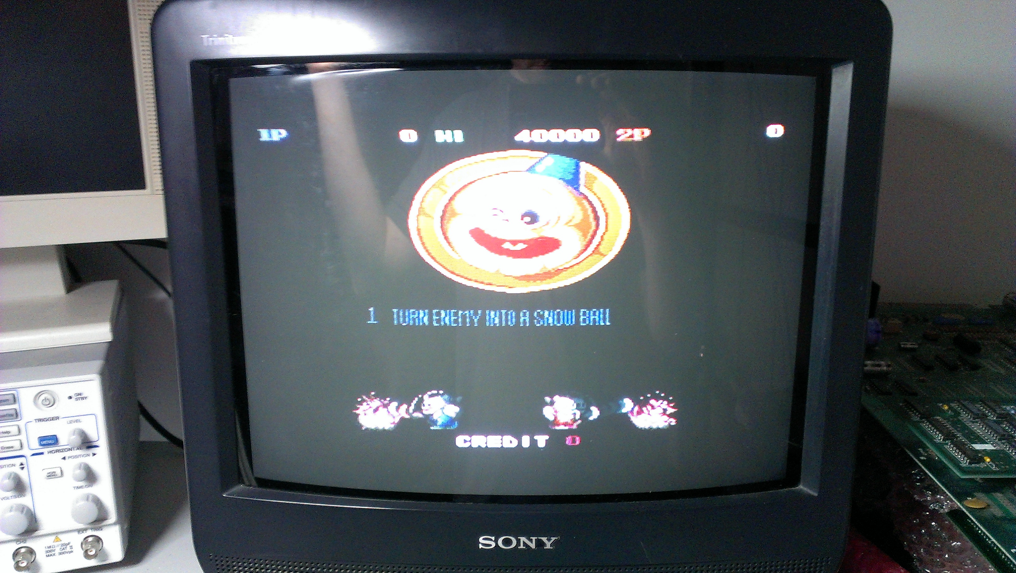
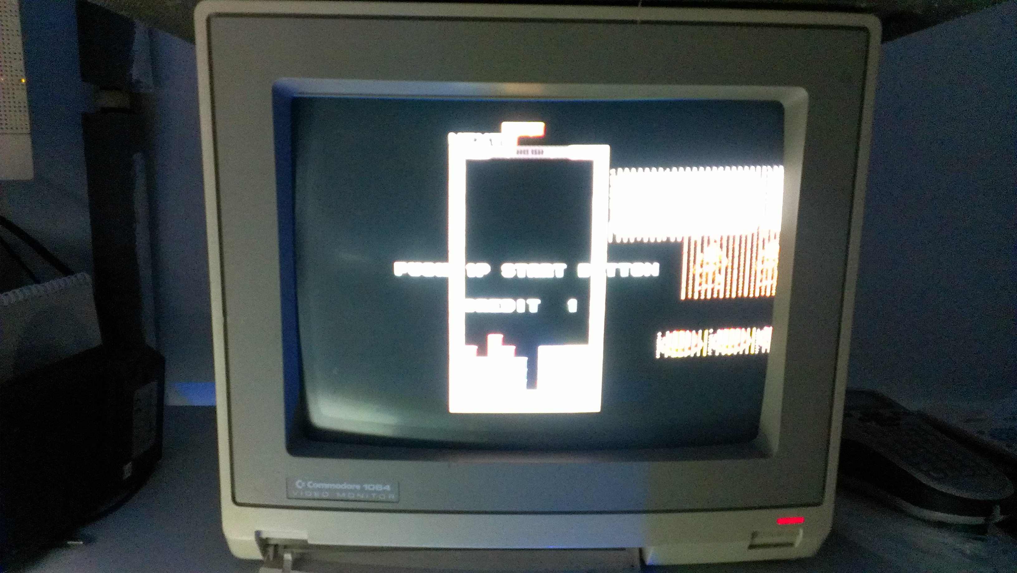
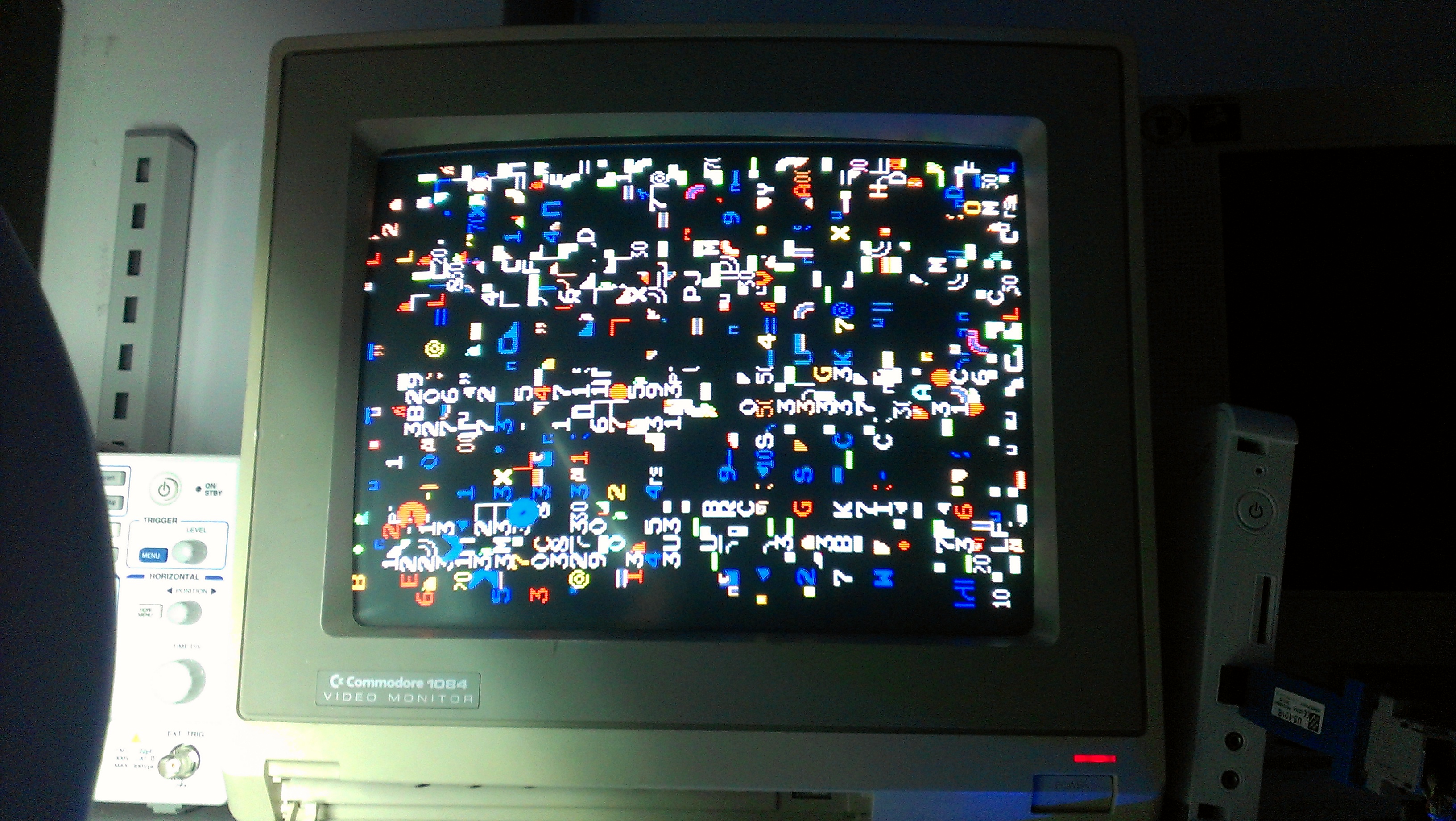
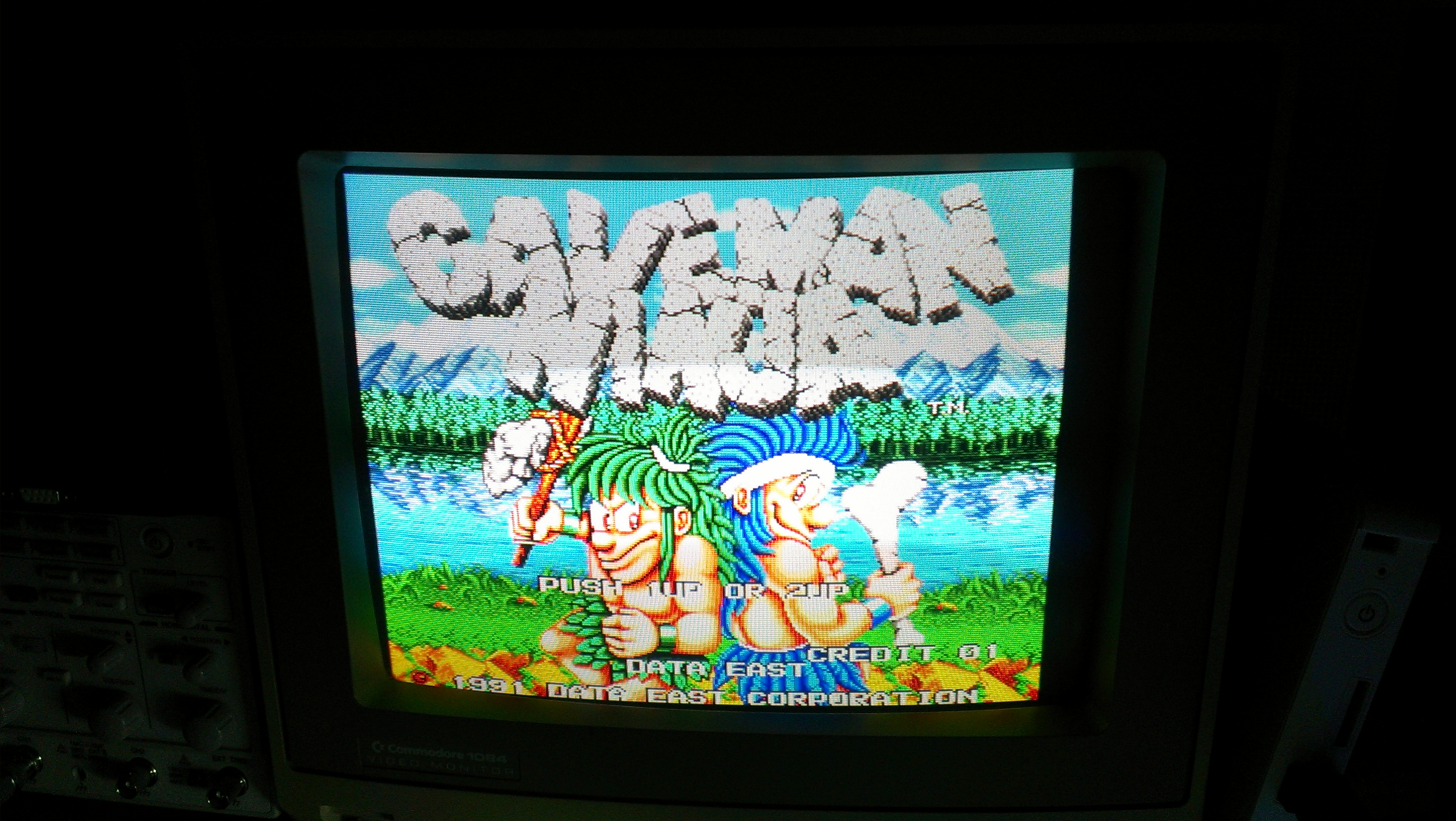
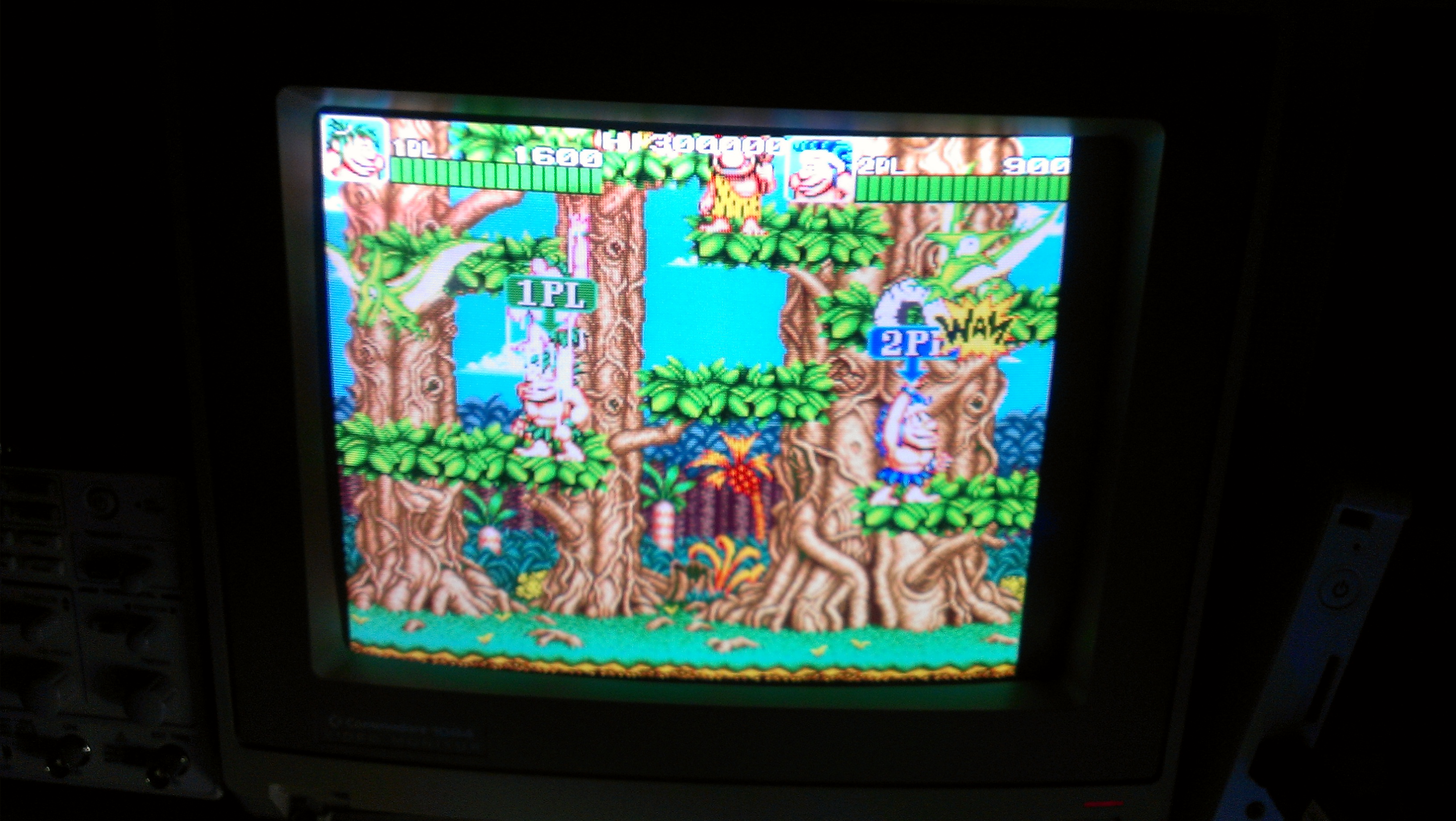
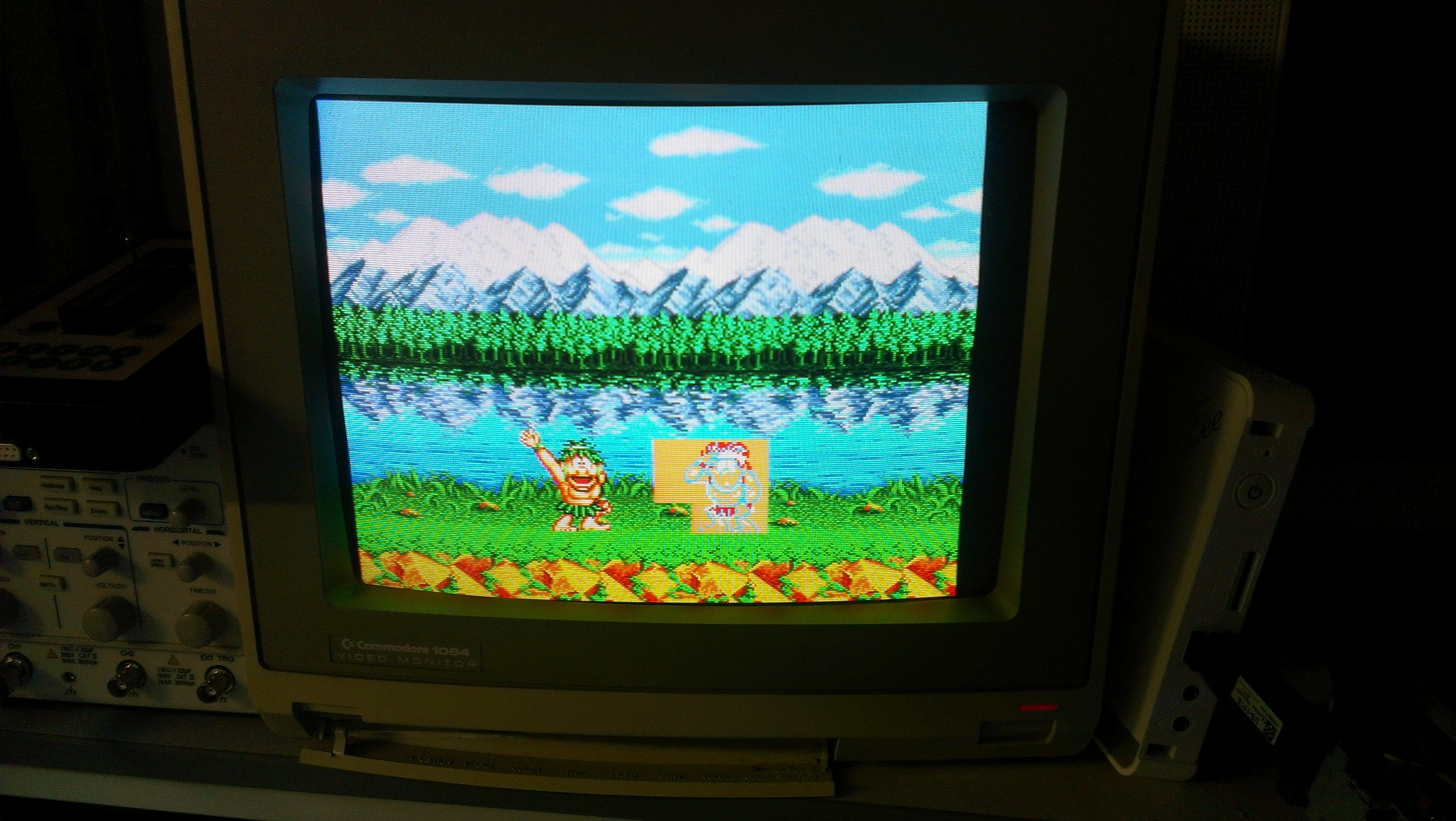
Nearly 12 months ago my Rainbow Islands went a bit crazy and kept giving me random crashes like the following

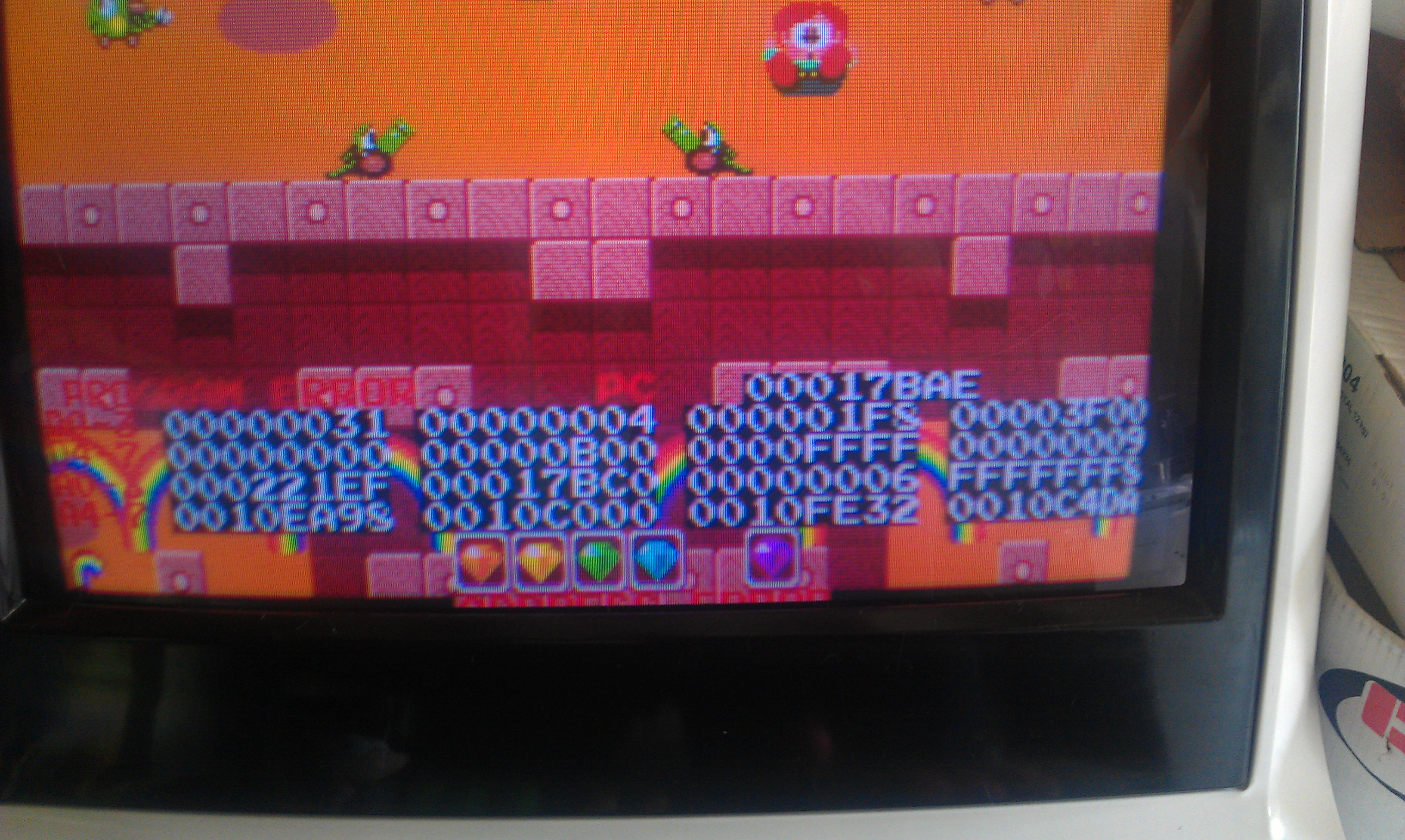
I thought I had sorted it with a simple ROM change but after a lengthy gaming session recently I discovered that this was not the case.

I couldn’t find anything wrong with this board. Sometimes I could play it for hours, sometimes it crashed at startup, sometimes it wouldn’t even start up at all.

Whilst I never gave up hope that I would find the fault I just didn’t know where to start.
My goal here is to document all the code with comments, create a decent set of schematics for the PCB and basically note any points of interest within the code and hardware.

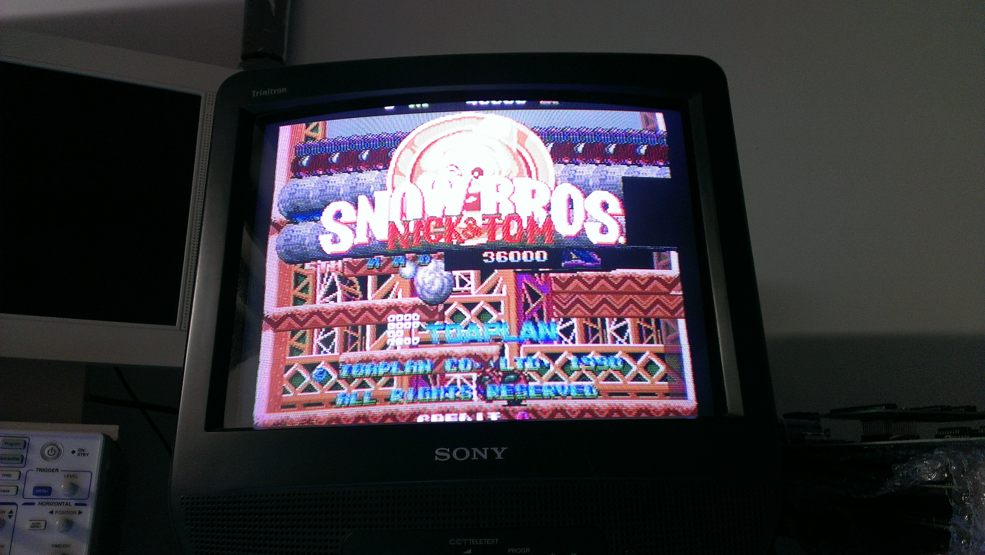
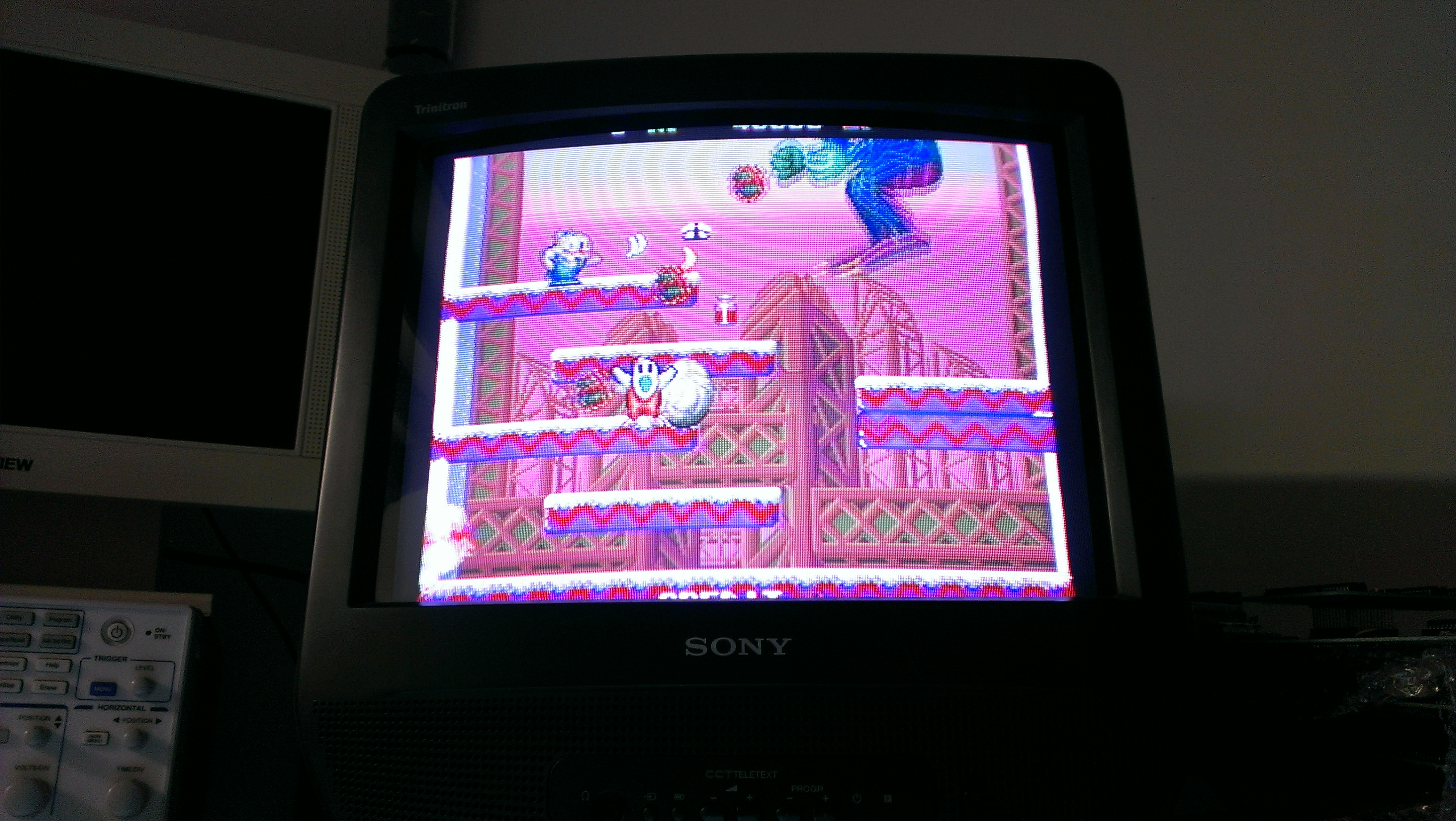
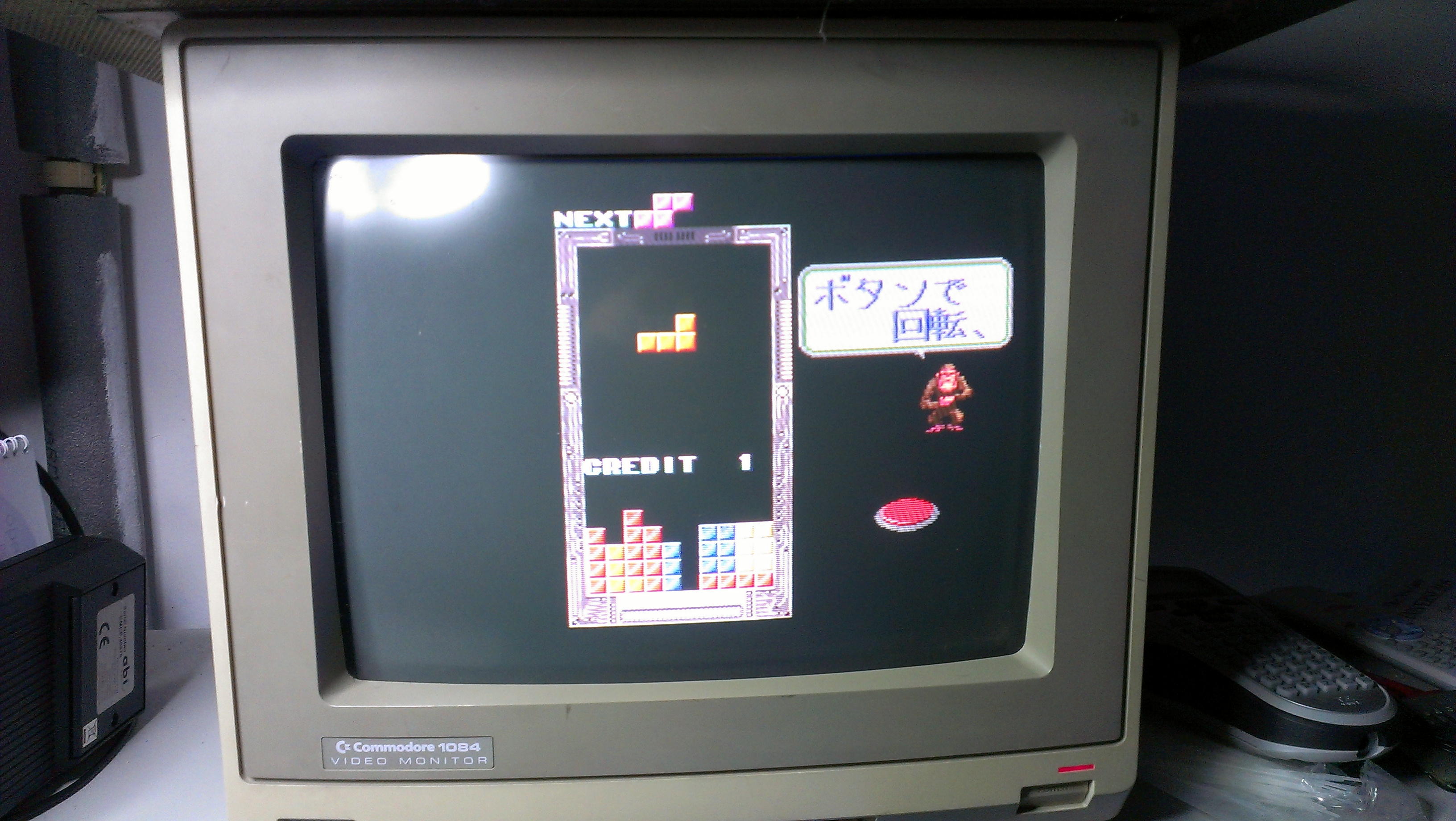
Tonight I feel confident in saying that I have fixed my board.
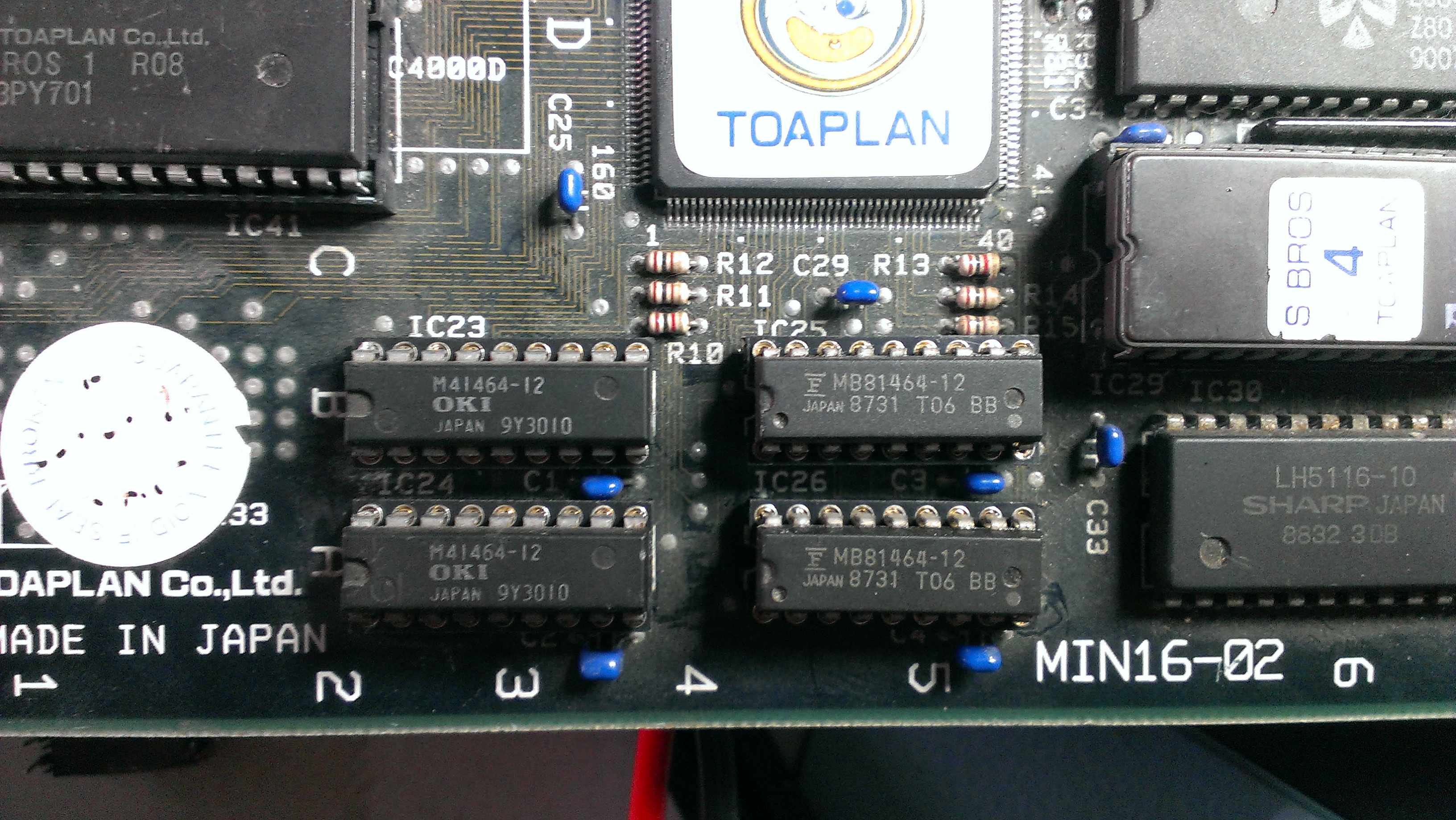
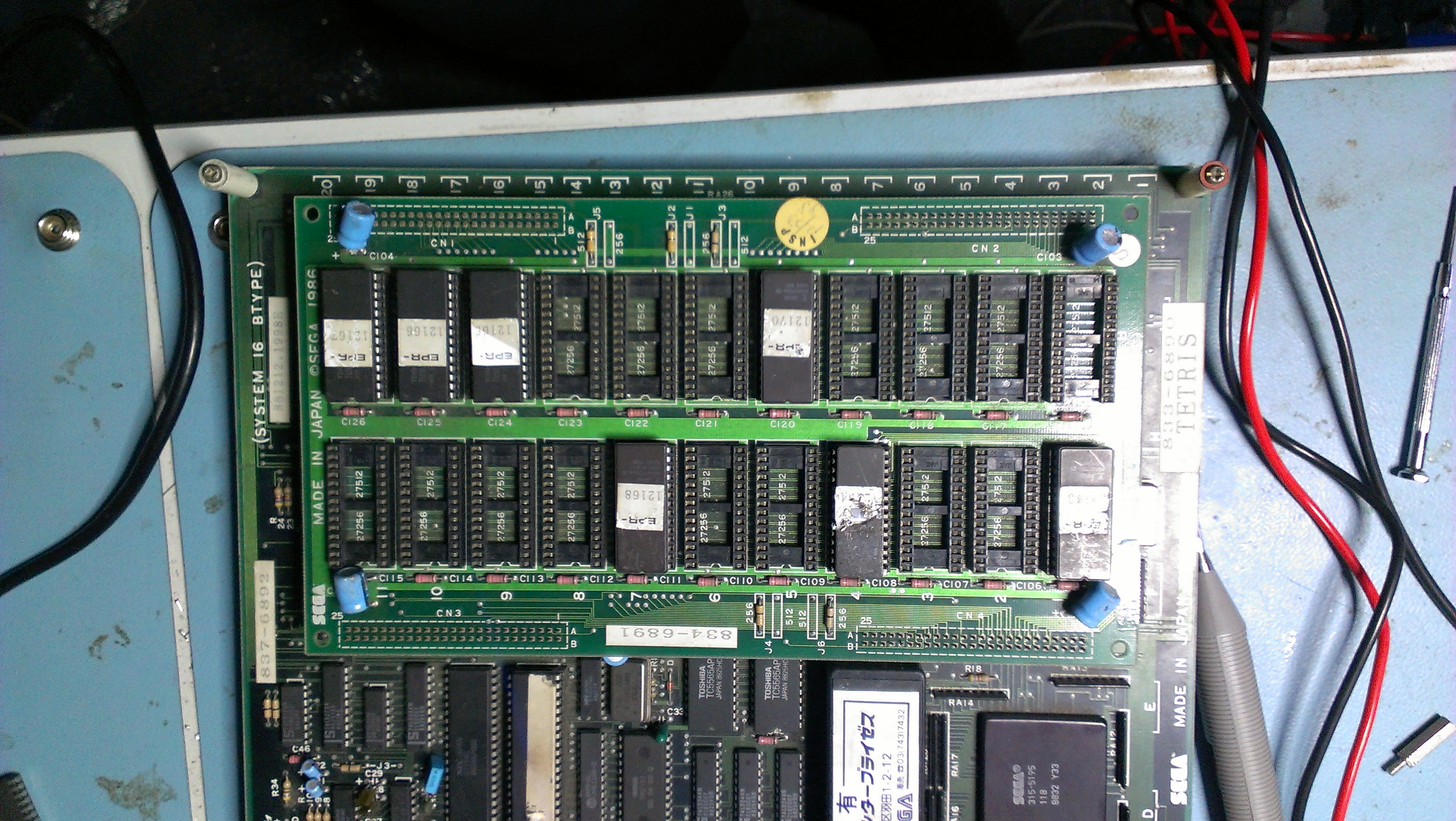
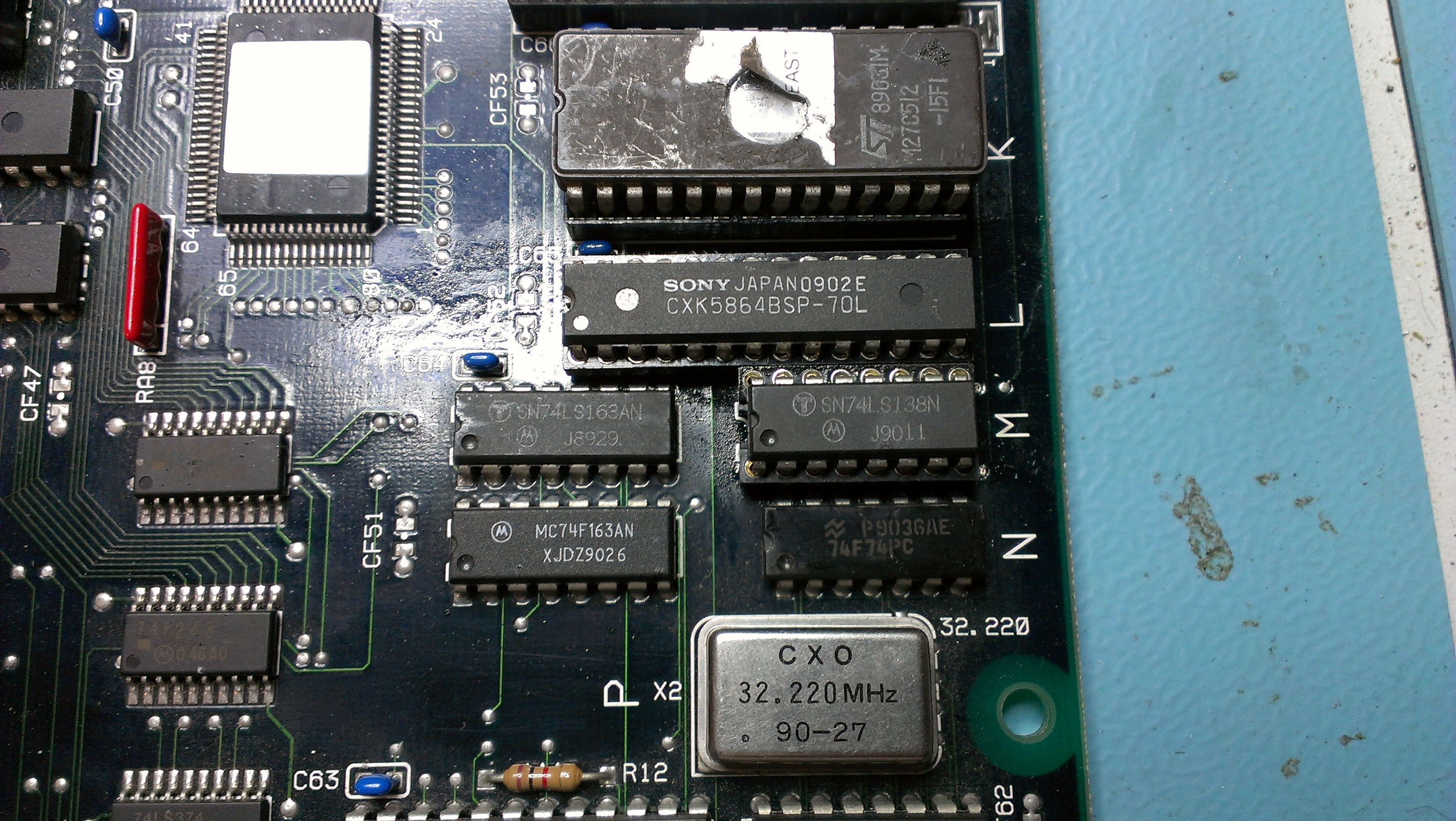
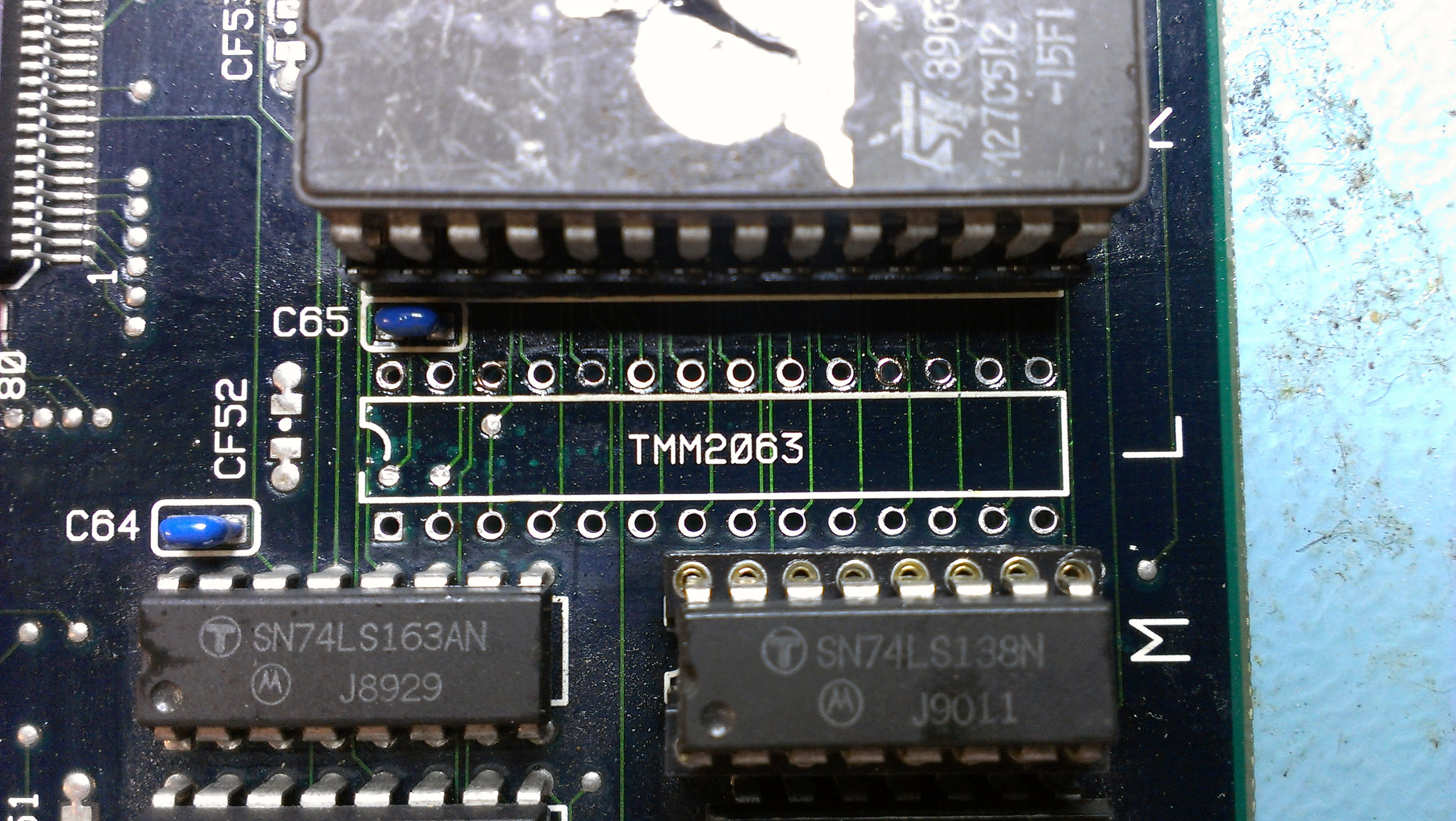
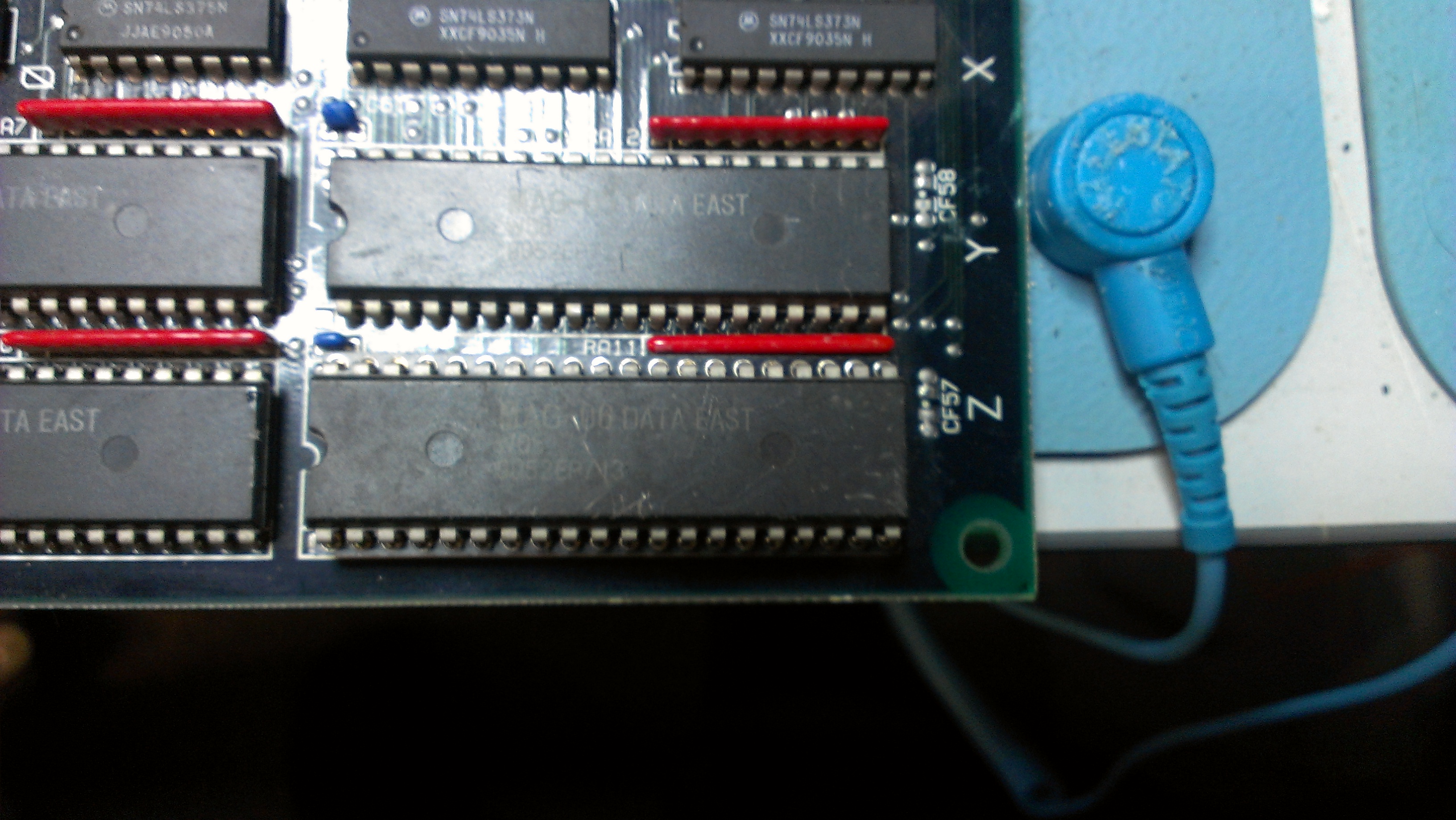
While I has adding to my schematic, trying to find where a trace ultimately ended up, I found that pin 9 of IC57 (74LS138) was tied to VCC (kind of anyway, it had a resistance of 38 ohms).
The pin does in fact go to pin 19 of a 74LS244 at location IC79.

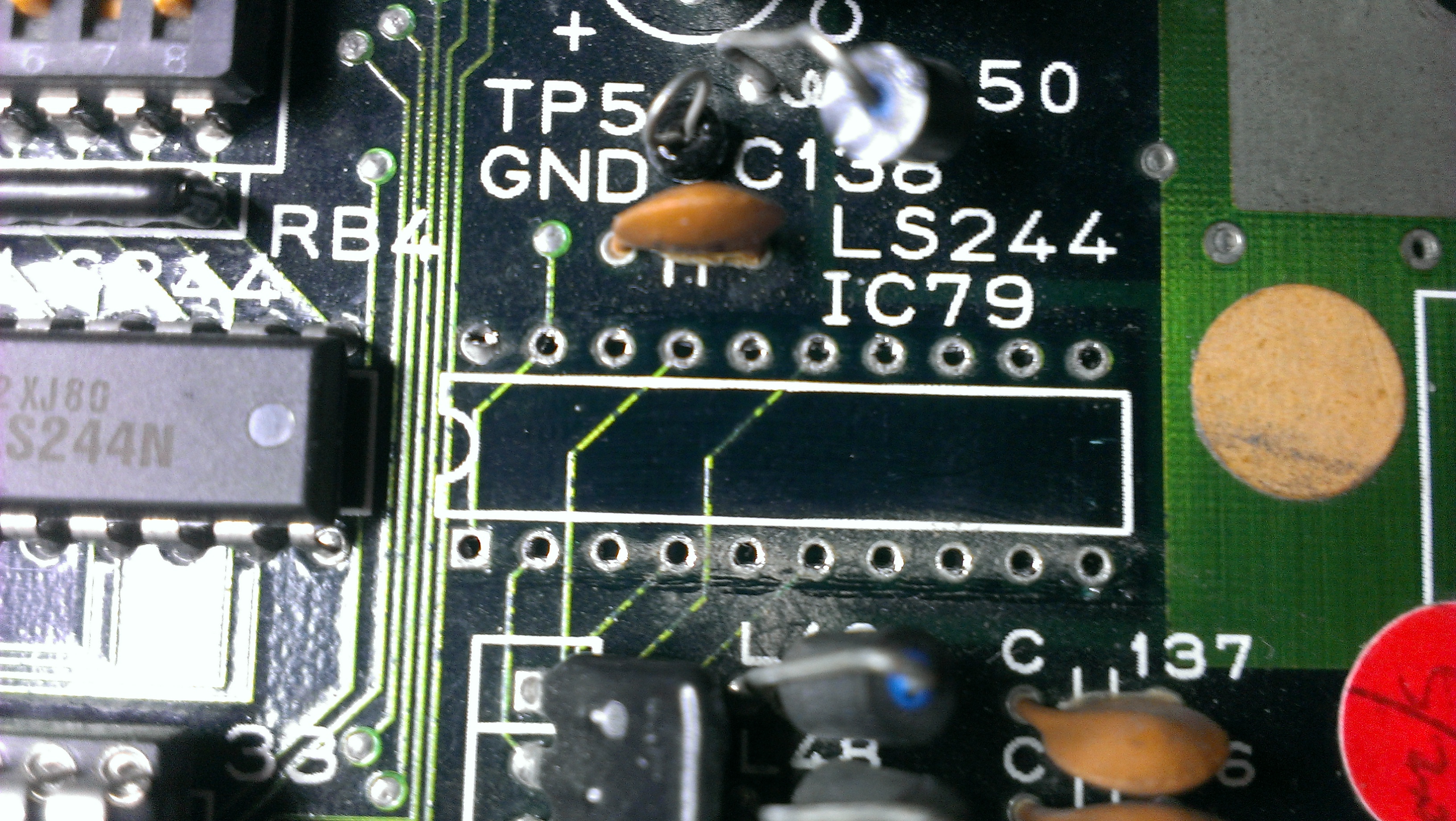
I removed the chip and it failed all tests, the connection to VCC also disappeared. I’ve replaced this chip and all seems to be well in my world once again.

For all those people that have asked me in the past “how long does a repair normally take?”. Although this kind of fault is quite rare, it has literally been 12 months of chipping away at different things. Had this been any other game then I would likely have given up on it a long time ago.

 Posted by at 9:11 pm

Snow Bros repair log #1

 PCB Repair Logs, Repair Logs  Comments Off on Snow Bros repair log #1
Apr 272013
 

Ive decided its time to make a start on the huge back log of repairs that I need to get finished.
Today Snow Bros was on the cards. It was a fairly recent purchase but as I really like the game it was first on my list.

Board boots up and passes its self tests but had big graphics problems.

Cant tell from the pictures but the screen is also flashing.

This board is tiny so I started looking for RAMs that weren’t program or sound related and shorting a couple of data lines together. There is a bank of 4 41464 RAM chips in the bottom left corner that would appear to be screen RAM.

First off I found the /OE on the left hand 2 were shorted to ground so I desoldered them. At some point a track had burnt out and was shorting against the ground pin above it. Removing this short gave me this

Much better, the colours are now sorted but the screen was still flashing and the graphics on the title screen left trails of the image. I checked the RAM chips I had removed and found a dead one.
I just went ahead and desoldered the other 2 RAM chips. Again, one was good and one was bad. I replaced these chips with an 81464 from a scrap board.

All working now. Ill have a game on this later.

 Posted by at 6:04 pm

SEGA Tetris repair log

 PCB Repair Logs, Repair Logs  Comments Off on SEGA Tetris repair log
Feb 022013
 

Got a Tetris that was sold as faulty.
As with pretty much any PCB I buy, a visual check was carried out and straight away I found this capacitor.


The board came with an adapter but looked a mess and the wire was far too thin on the power lines so I swapped it out.
I also found a couple of pins touching in one of the unused connectors


And finally I found the sound pot was no soldered in at all and was missing its ground pin.


I took a pot from an old scrap board and fitted it.


Now it was boot up time.


All looks ok so far, but…..


I initially thought it was a dodgy EPROM but they checked out fine. Then I realised that the EPROM at location B1 on the ROM board was missing.


I burned a new one from the Jap set and now we have this.


Everything seems to be working fine.
This board still has its battery installed in the FD1094 and surely will be coming to the end of its life by now. I don’t trust myself with a battery change but I think I have desuicided ROM’s so will just wait until it dies completely or I will sell it on as I cant imagine wanting to play this in my cab.

 Posted by at 2:47 pm
Jan 202013
 

Quite a few weeks ago I took part in a charity event which saw me win a personalised copy of Pac Manic Miner Man written by Jim Bagley and runs on original Pac-Man hardware.
My good friend Equites from the J+ forums hooked me up with an original Pac-Man board and after making up a jamma adapter it was clear some repairs were needed.

The board has 2 daughter boards for the custom chips, one of them being a 3rd party one.

A quick inspection revealed this

I reseated the the sub board and the game booted to random garbage on screen

The boards watchdog was also “barking” so I check the 4 program ROMs, all of which were recognised by MAME.
This was the ideal time to hook up the Fluke 9010 and see what was going on.
First off it showed me that the RESET line was active so I told the Fluke to ignore it.
I carried out BUS and ROM checks. All of which returned OK. I tried to carry out RAM tests and DIP switch tests but I couldnt read anything back other that “F7”.
Something was wrong at address line 14 and it pointed towards the 3rd party sync bus PCB. Equites confirmed that the previous owner of the board had this module plugged in backwards so that confirmed my suspicions.
Andyman from the J+ forum also showed me a picture of what his look like without the Sync Bus PCB attached and it was identical.

I spent quite a bit of time wondering the best way to tackle this. I could buy another 3rd party module, or, as the schematics for a TTL version are available I could build my own. My saviour came in the form of the fantastic reprogrammable device from FPGAARCADE.COM.
I have a spare here that is currently programmed with the Commodore 64 PLA replacement but I do have the tools required to reprogram it. What I didnt have was the code to program it with. A quick email to Mike, the owner of FPGAARCADE and he sent me the file required.
Once I had the chip reprogrammed (took ages as my current programmer didnt want to bother working) I fitted the device and….

As all the RAM chips are socketed I pulled them and tested them. The 2114 RAM at position 4R can back as failed. I have some spares of these so fitted a new one and fired the board up again.

SUCCESS!
This game will sometimes be running Jim Bagleys Pac Manic Miner Man so now was an ideal time to try the ROMs out on the actual hardware.

Very happy to get this running.

Thanks to:
Equites for the PCB
Mike at FPGAARCADE for the Sync Bus program file
Andyman for help diagnosing
Jim Bagley for creating PMMM

 Posted by at 6:55 pm

Caveman Ninja repair log

 PCB Repair Logs, Repair Logs  Comments Off on Caveman Ninja repair log
Dec 092012
 

Where to start with this one.
My good friend brought this round a while ago with the fault of jailbars down the screen and no sound.
After messing around a bit we couldnt even get the game to boot on my setup no matter what we tried. He left it with me and ive been chipping away at it for a month or two now whenever I get time.
Ive finally got this thing up and running.
First this I found was two PLD’s, TJ-0 and TJ-1, were getting really hot.
As I have a couple of spare Caveman Ninja boards I did a swap and the game booted. Strange thing though, those PLD’s actually work in my other semi working board.
So now we have this

and no sound was present either.
Jailbars are usually a sign of a failed ROM so off the the tile ROM’s I go.
Found MASKROM MAG-02 had a few floating data pins. Replaced this for one off my scrap board and we get this

Graphics are back. Now onto the sound.
Looking first at the two OKI M6295 chips I could see neither of these were being enabled. If I pulsed the enable lines I could get various sounds to play. This tested the rest of the sound circuit so I knew it was good.
I traced the enable lines back to a 74LS138 decoder which wasn’t doing a great deal despite having what looked like good inputs. I removed this and it was indeed dead so replaced with a new one.

Still no sound though.
I could see the sound CPU and ROM were being addressed properly so next up was the RAM. On this board it was a TMM2063 chip. I could see activity on the data lines but it was struggling to drive them up to logic HIGH so removed that and that too failed a test.

I replaced it with a CXK5864 chip. Still no sound.

I started looking into how the sound section worked and found that the custom 104 protection chip is responsible for activating the sound.
I got in touch with a guy called Bryan who wrote the MAME driver and he gave me some nice information of its operation and basically pin pointed my issue to this chip.
At first I tried reflowing the pins but it made no difference so after a bit of debate with myself I took the plunge and removed the chip

I replaced it with one from my scrap board. WE HAVE SOUND!

And thats it, or so one would think. After about 2 minutes of playing this game, some of the sprites started to go a little crazy.

Going over the sprite ROM’s I found another one (MAG-06) with a floating data line. Replaced this with a spare and all is well once again.

Without a scrap board to take customs from this would have been one for the scrap pile.

 Posted by at 11:00 am