Raiden II repair log

 PCB Repair Logs, Repair Logs  Comments Off on Raiden II repair log
May 032014
 

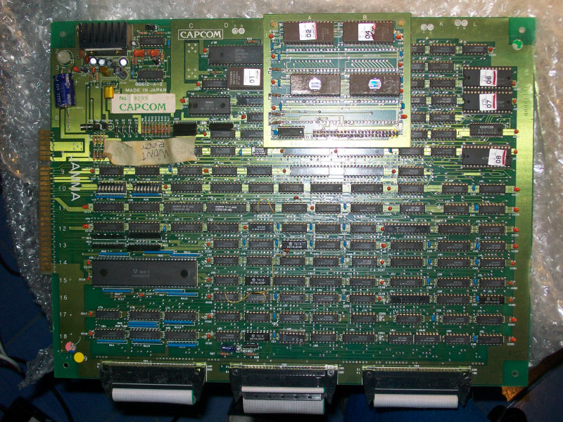
Got a cheap Raiden II (set 4, Italy revision) PCB recently:

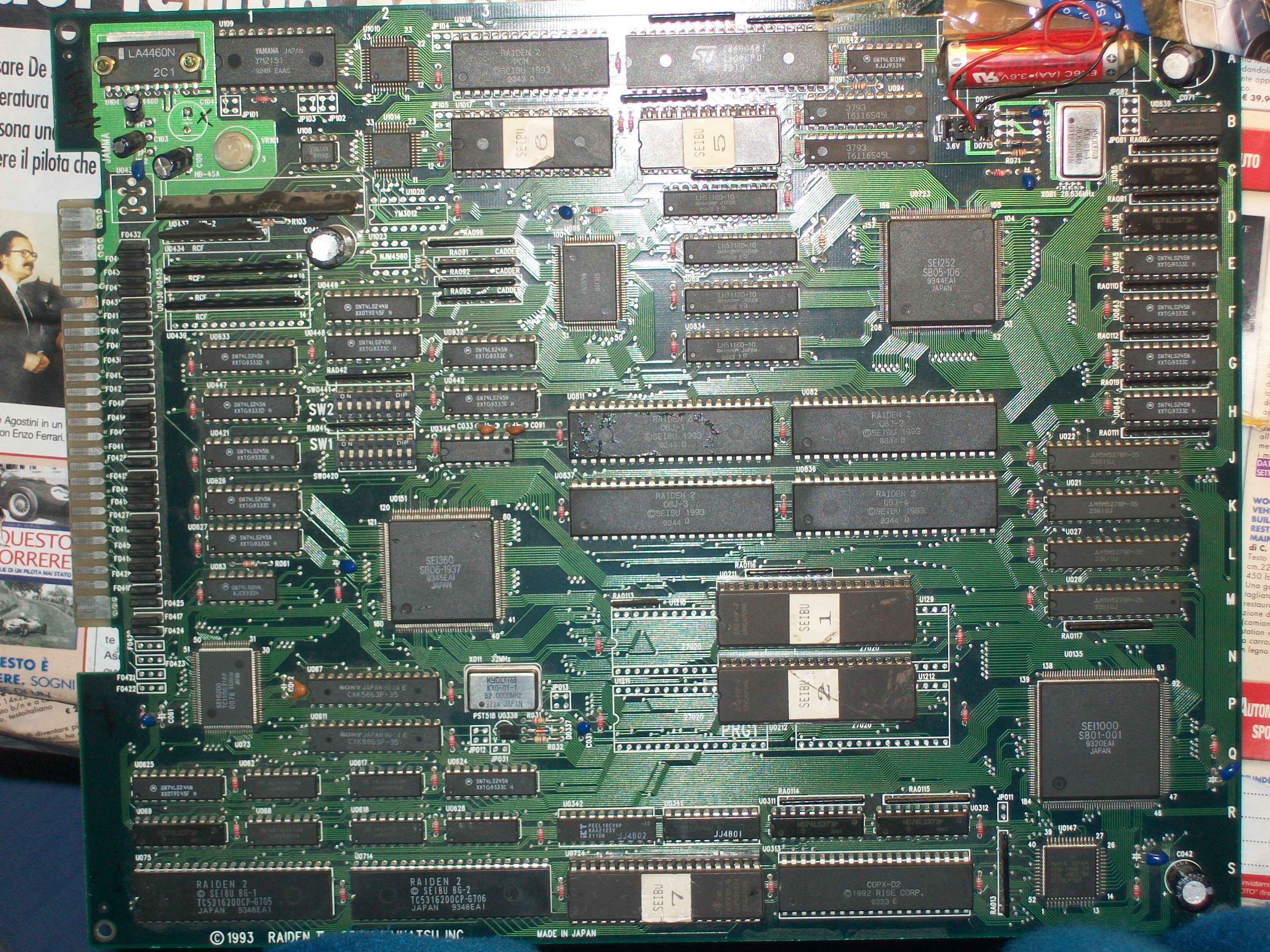
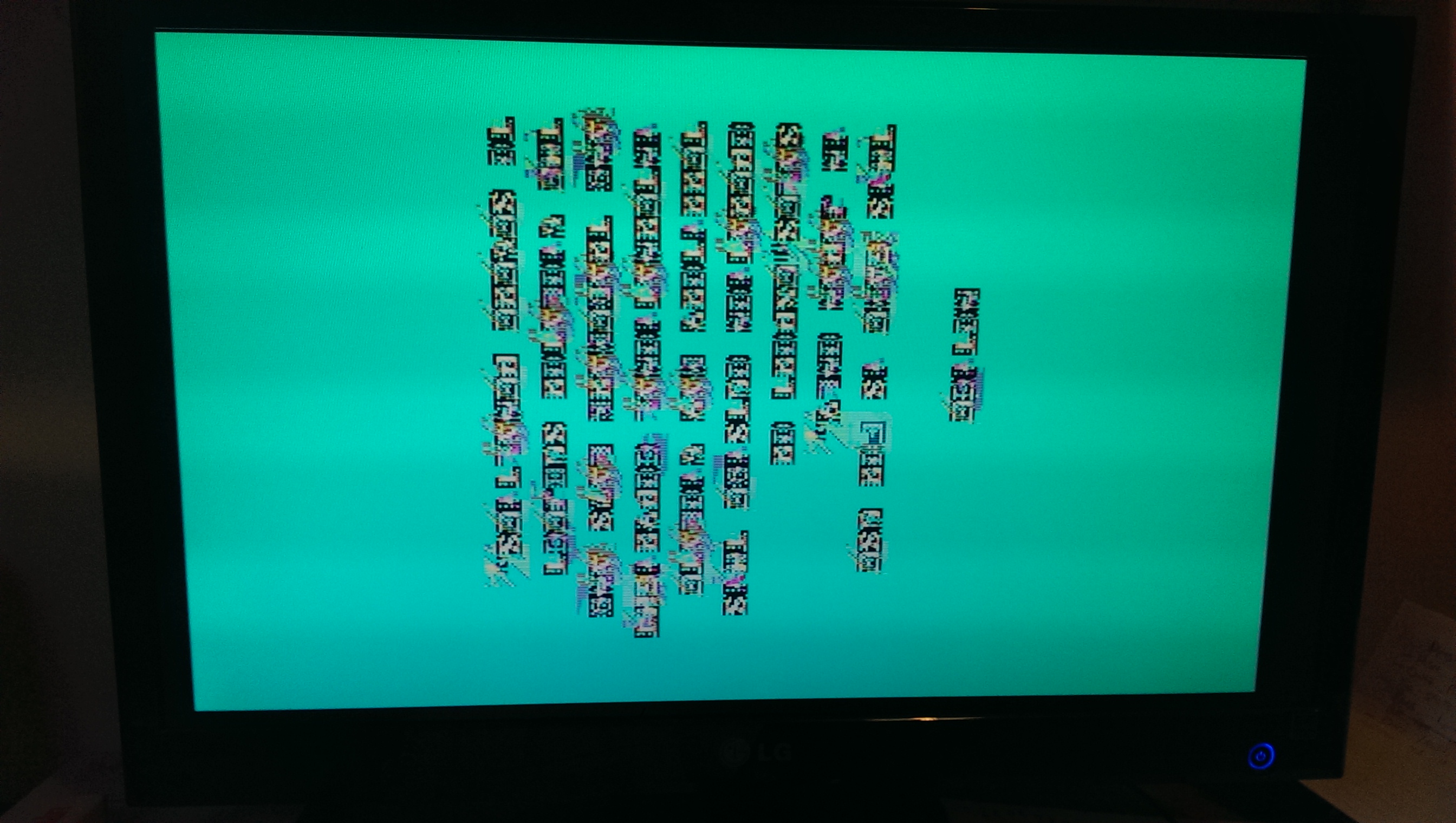
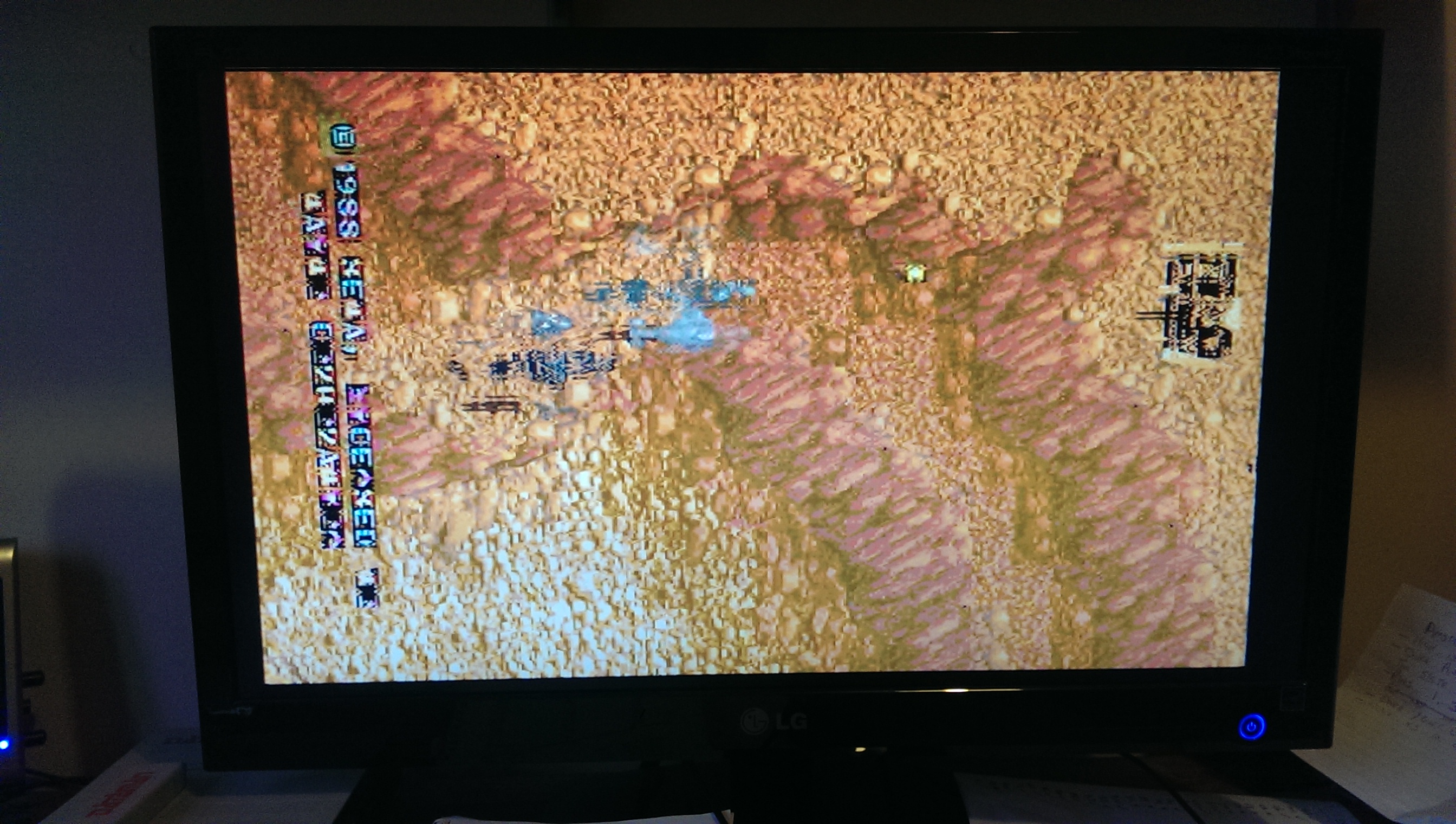
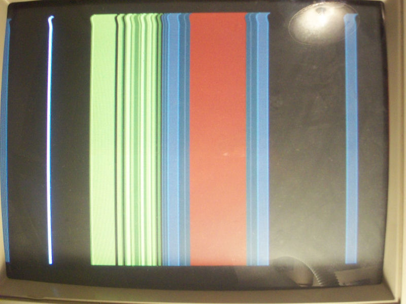
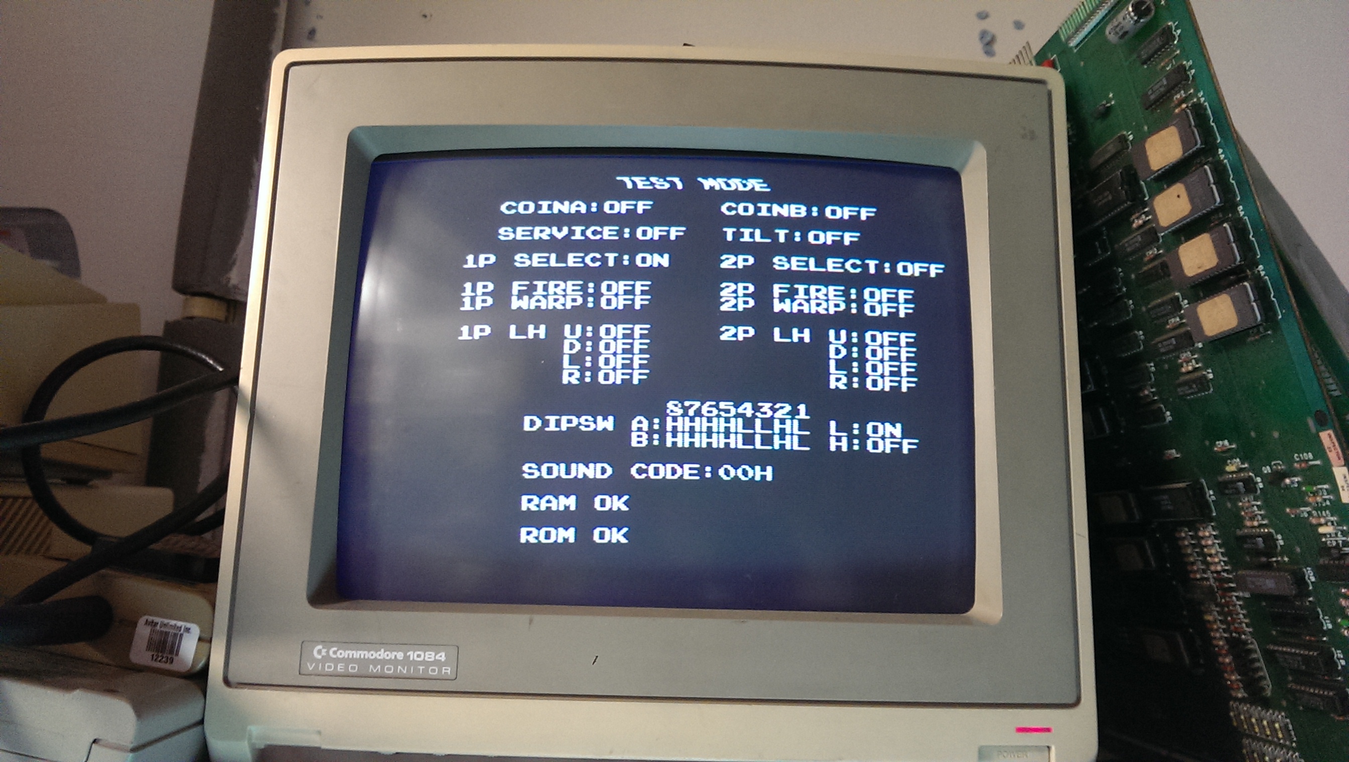
Seller claimed PCB had a video SYNC issue so I fired up it sure of the scenario I was going to face :

There was no SYNC at all (measured 549Hz on pin13 solderside of JAMMA edge) but the thing that made ​​me suspicious was that there was no activity on address/data bus of CPU (NEC V30) and program ROMs like the system never got initialized.

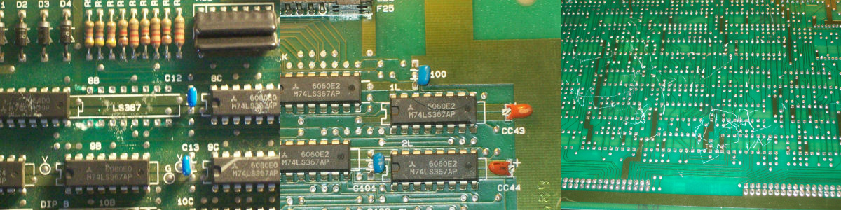
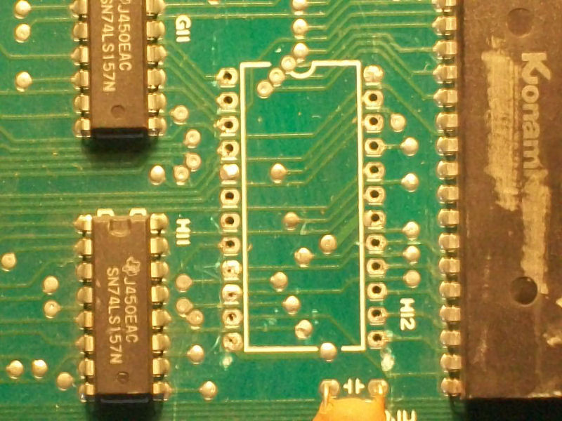
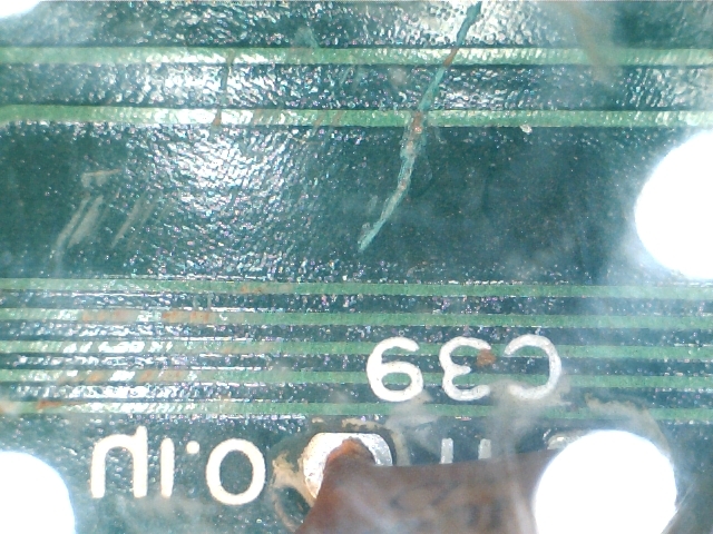
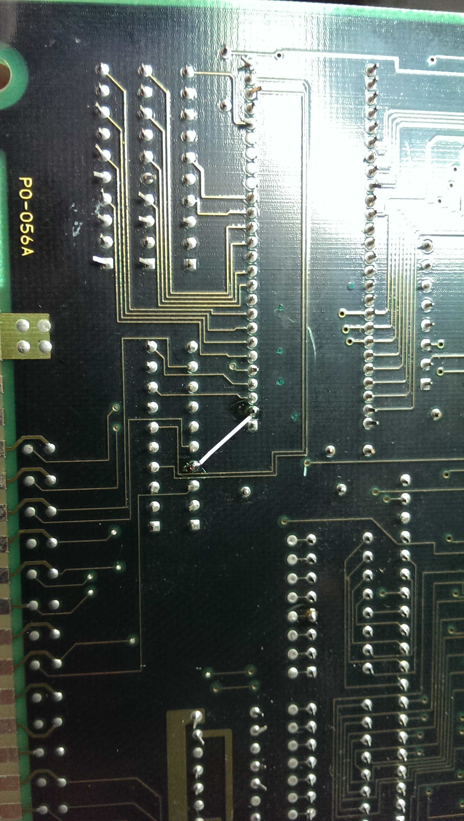
So, as usual, I start my visual inspection and found this:

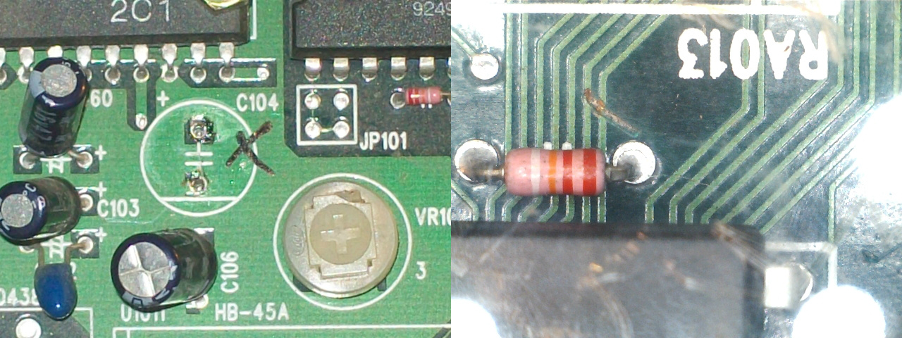
If the missing capacitor  (which filters the +12V for the LA4460 audio amplifier) was not the cause of the issue for sure, I thought the broken track would have been the culprit but  I was wrong since, once restored, I got the same rolling screen above.

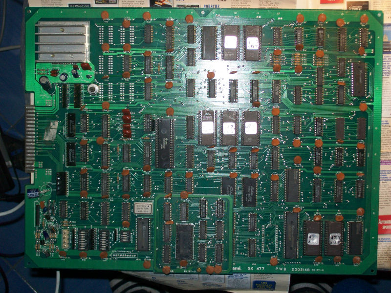
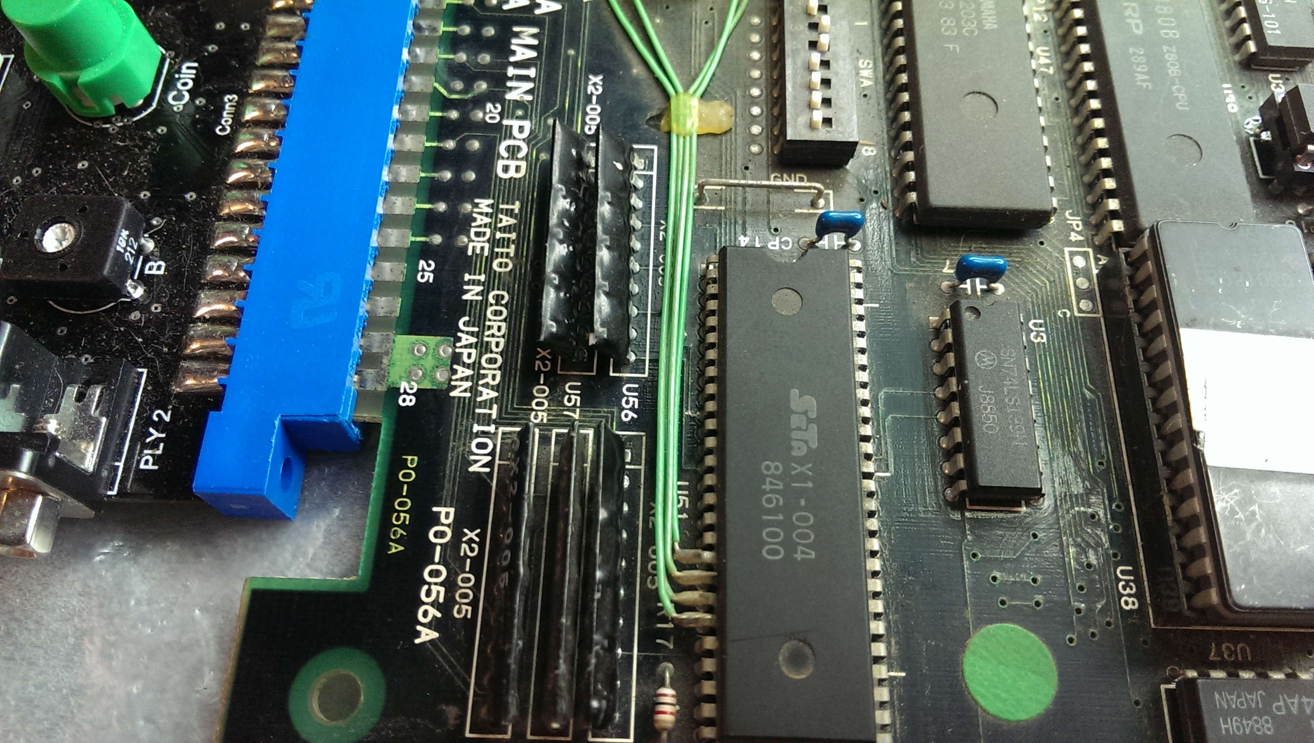
PCB has few common ICs (74LS245 and SRAM mainly) but a sufficient number of ASICs so I consulted the MAME source which is like a bible for every arcade repairer since it’s a an inexhaustible source of hardware information.And I found that among the various ASICs, the one marked ‘SEI1000 SB01-001’ is responsible of the main protection, this would have explained why the PCB didn’t boot at all:

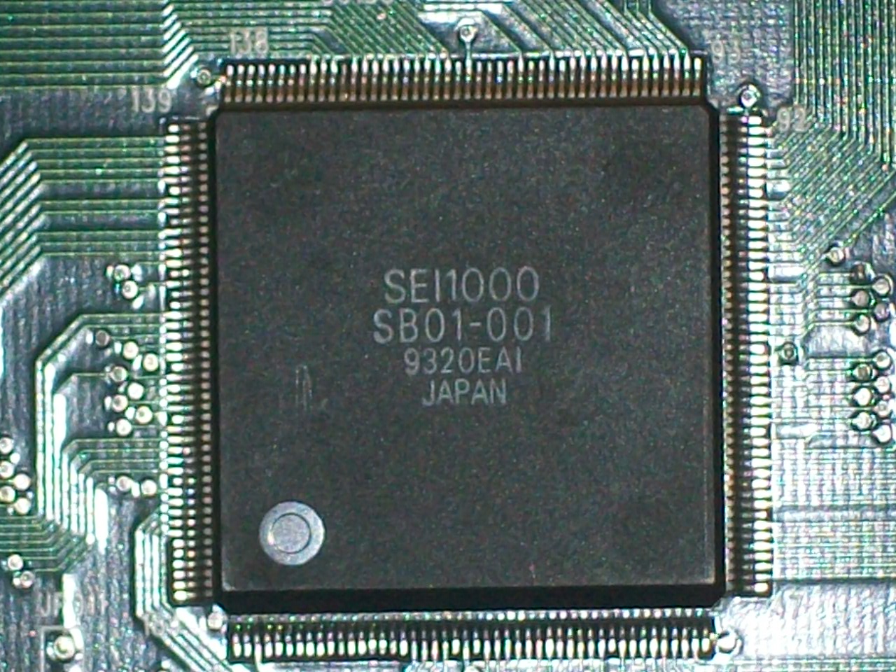
Its package was a 184 pin QFP with a fine pitch as you can see from picture.Armed with a small needle I started to test the tightness of each pin and found that almost half of them got detached from the pads when I gave force.So, it was time for a reflow at 390° with my hot air station which I had to repeat 4-5 times plus some final passes with the tip of the soldering iron to get a good result.

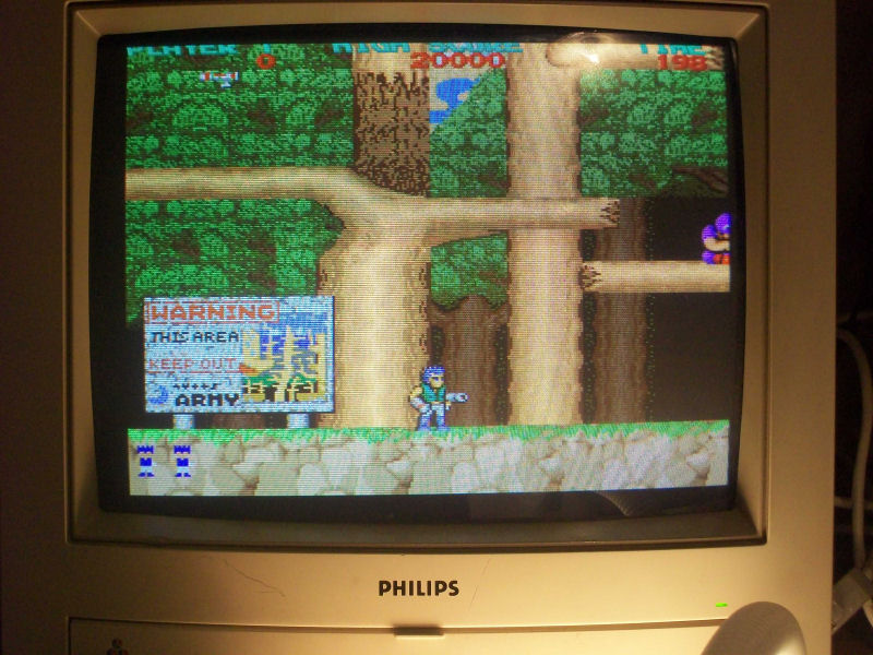
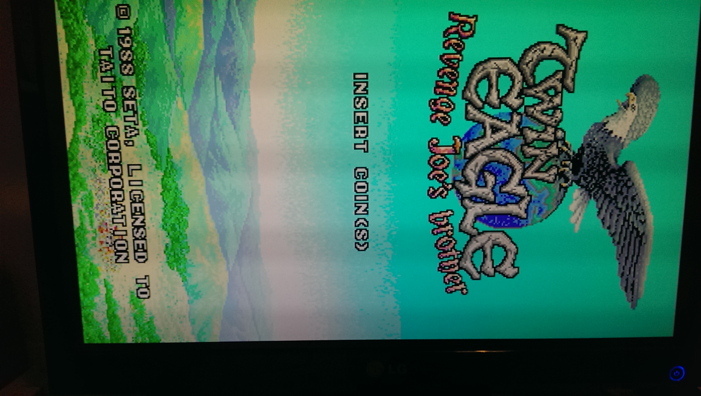
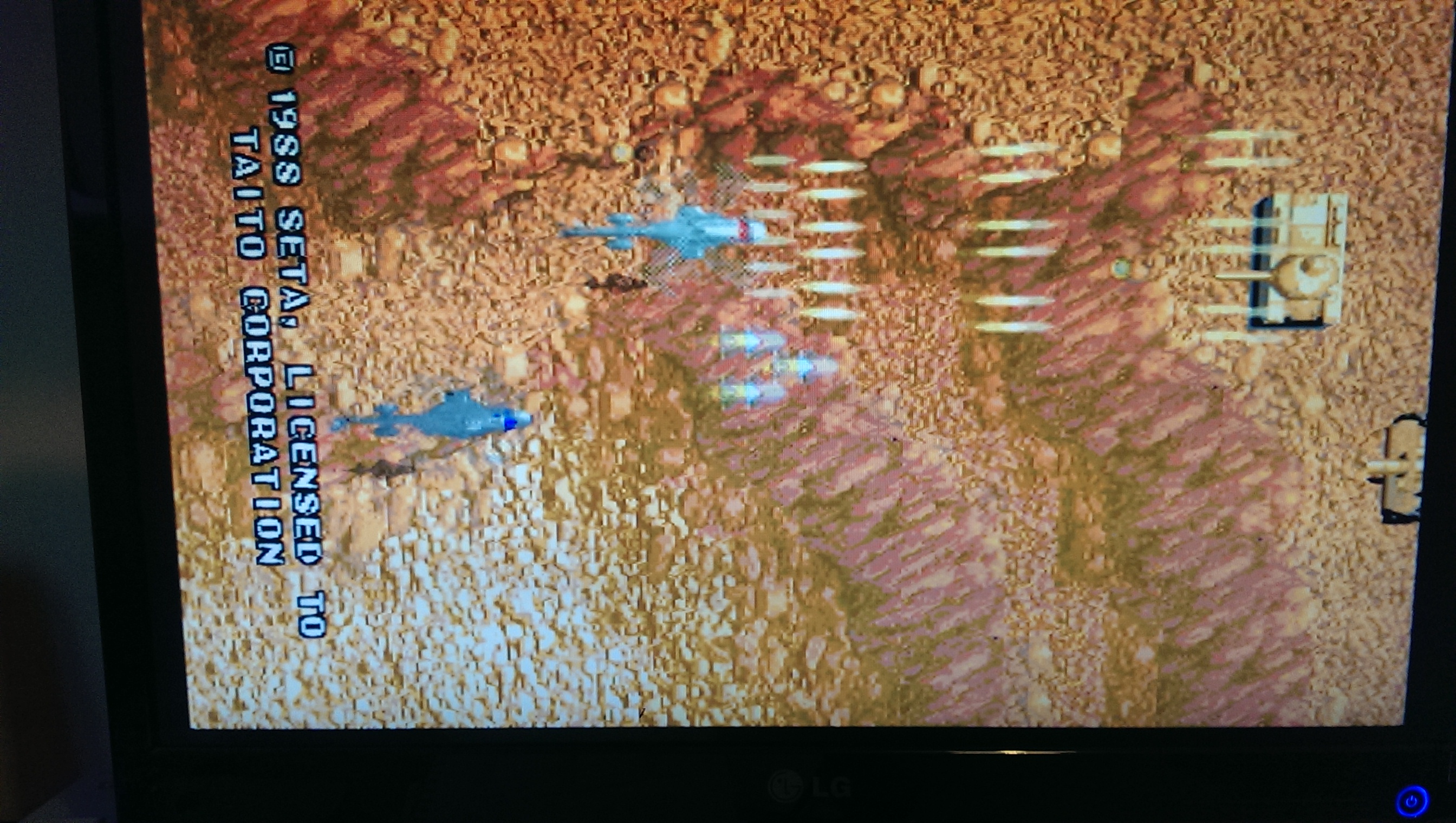
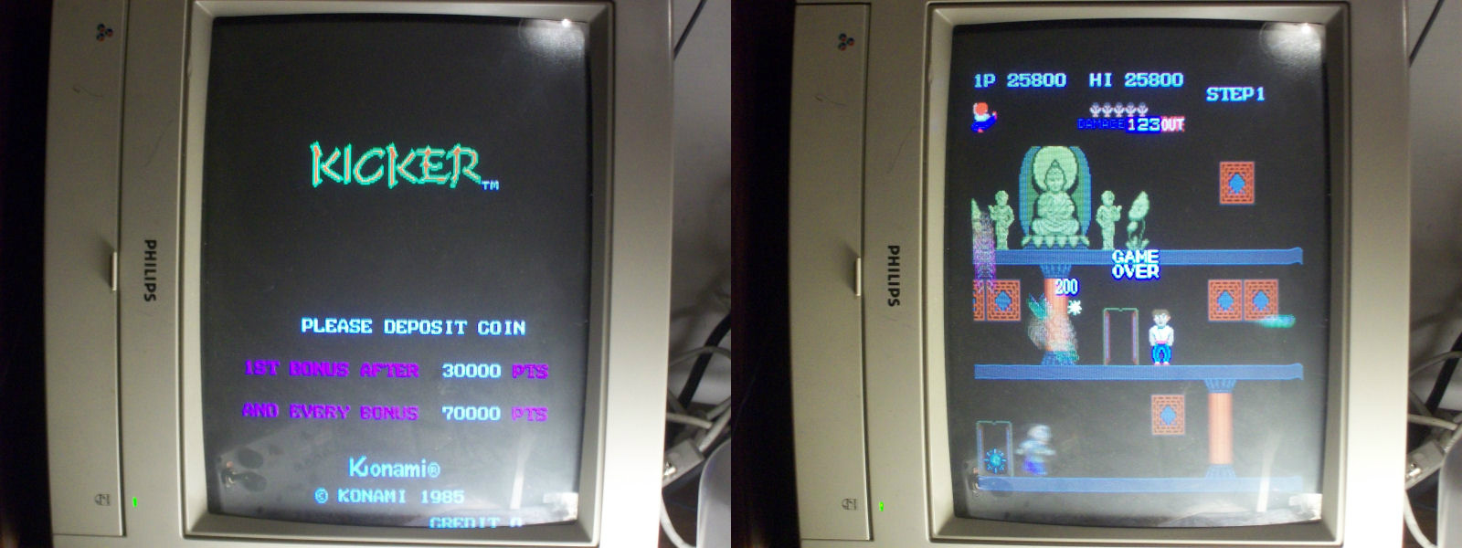
Powered up again and :

SUCCESS!Another PCB saved from the trash and a very good vertical shoot ’em up!

 Posted by at 4:15 pm

Bionic Commando repair log #2

 PCB Repair Logs, Repair Logs  Comments Off on Bionic Commando repair log #2
May 012014
 

Another new day, another PCB repair. An easy and lucky one with a strange epilogue though.Got this original Bionic Commando PCB from Ebay as non working:

IMAG0236

When I received the board I noticed a piece of tape on it saying “WON’T BOOT” so I was ready to a static garbage screen or worse, a nice black one.So I powered up the board and I got this instead:

IMAG0239

Video had jailbairs all over the screen, gameplay and sounds were OK.So, as usual, before starting my troubleshooting, I made a visual inspection that revealed :

One 74LS367 was missing, another one was cracked and, the icing on the cake, solderside of the video board had a lot of scratches but at the end I found only one broken track that I jumpered with a bit of solder.

So, fitted a new 74LS367 and replaced the cracked one, I was confident about but I was wrong, there was no change at all, jailbars were always present.

So, with the help of the schematics, I started to check everything related to the issue .I dumped the ROMs containing the tiles and they were fine against MAME,  did some in-circuit testing with my B&K 560A IC tester but nothing was wrong in the presumed involved parts of circuit.After some hours of investigations I was giving up when I decided to check the voltages on PCB.I measured +5.1V on a IC so I lowered it a bit but without immediate success.A little frustrated I powered off the board and then after some minutes on again and I got:

IMAG0238


I don’t know if this is really related to the voltages (I raised to +5.1 again and jailbars didn’t appear), the fact is I finished the game and no issue occurred again.Oh, I love the soundtrack of 1st level, it reminds me the happy days playing this game on my Commodore 64.Another day spent, another great classic added to my collection…

 Posted by at 9:25 pm

Twin Eagle repair log

 PCB Repair Logs, Repair Logs  Comments Off on Twin Eagle repair log
May 012014
 

Another of muddymusic’s boards here.
This one had graphics issues around the sprites.

Looking as the MAME source you can see that the sprites are held in the MASKROMs marked UA2-3, 4, 5 & 6.
Probing all the pins on these chips revealed that pin 25 on three of these chips was floating. These are 23C2001 MASKROM’s which a datasheet is easily available for.

The last ROM had a signal at this pin and the other three are all linked off it so there is a break somewhere on this trace. I patched this line and tested.
Almost there but still a little issue around the text.

A bit more probing found that pin 11 (A1) of ROM UA2-4 was also missing. Again I patched this from the adjacent ROM and tested.


All appears to be working now.

 Posted by at 8:11 pm

Kicker (Shao-lin’s Road) repair log

 PCB Repair Logs, Repair Logs  Comments Off on Kicker (Shao-lin’s Road) repair log
Apr 292014
 

Bought this PCB (among others) from Ebay as untested/not working:

IMAG0228

This, judging from the auction pictures and the GX477 serial, should have been an original Konami Shao-lin’s Road PCB but after dumping the EPROMs it turned to be a Kicker one (the overseas version).Anyway, before powering it up, a visual inspection revealed that one IC was missing:

IMAG0229

Now, in absence of any schematics, looking at some PCB pictures on the Net, I figured out the missing IC was a M58725P SRAM pin to pin compatible with a 6116 (or 2016, 2018 etc..).Fitted a socket and a 6116 SRAM, I powered up the board (it uses the Konami Classic pinout, the same used for many other Konami games) and I got this:

IMAG0231

These patterns of lines were changing on the screen sign that the board was running fine , infact I could coin-up and hear all the sounds but the video had some issues related to timing signals used to draw display, I presumed.

So, with the fear that one of many custom (with scratched ID) was bad, I started to test the ICs with my HP 10520A logic comparator and logic probe.All was fine until I came across a 74LS74 (location C6) whose ouputs was stuck low.Its data input pin (connected to an output of a 74LS161) had no activity at all but the near via which had to be connected to was pulsing!Infact my multimeter didn’t buzz on this and a closer look revealed this:

IMAG0032

Bridged this broken track with a bit of solder, I powerer up the board again and I got:

IMAG0235

Board 100% fixed and another classic one preserved!

 Posted by at 11:44 am
Apr 132014
 

Another one of muddymusic’s PCB’s.
Everything looks fine with this one until it is coined up then the game starts automatically.
If I enabled test mode by switching switch 3 on DSWA then I could see the start button for Player 1 was stuck on.

I initially thought this was going to be a sticking point as all the inputs go to a custom chip however I found that the trace from the pull up resistor array to the custom was broken somewhere.
There were no visible breaks so it must be under the silkscreen somewhere.

Running a patch wire from pin 2 of the custom chip to the resistor array fixed the issue.

Quite a fun game it is too.

 Posted by at 10:42 am