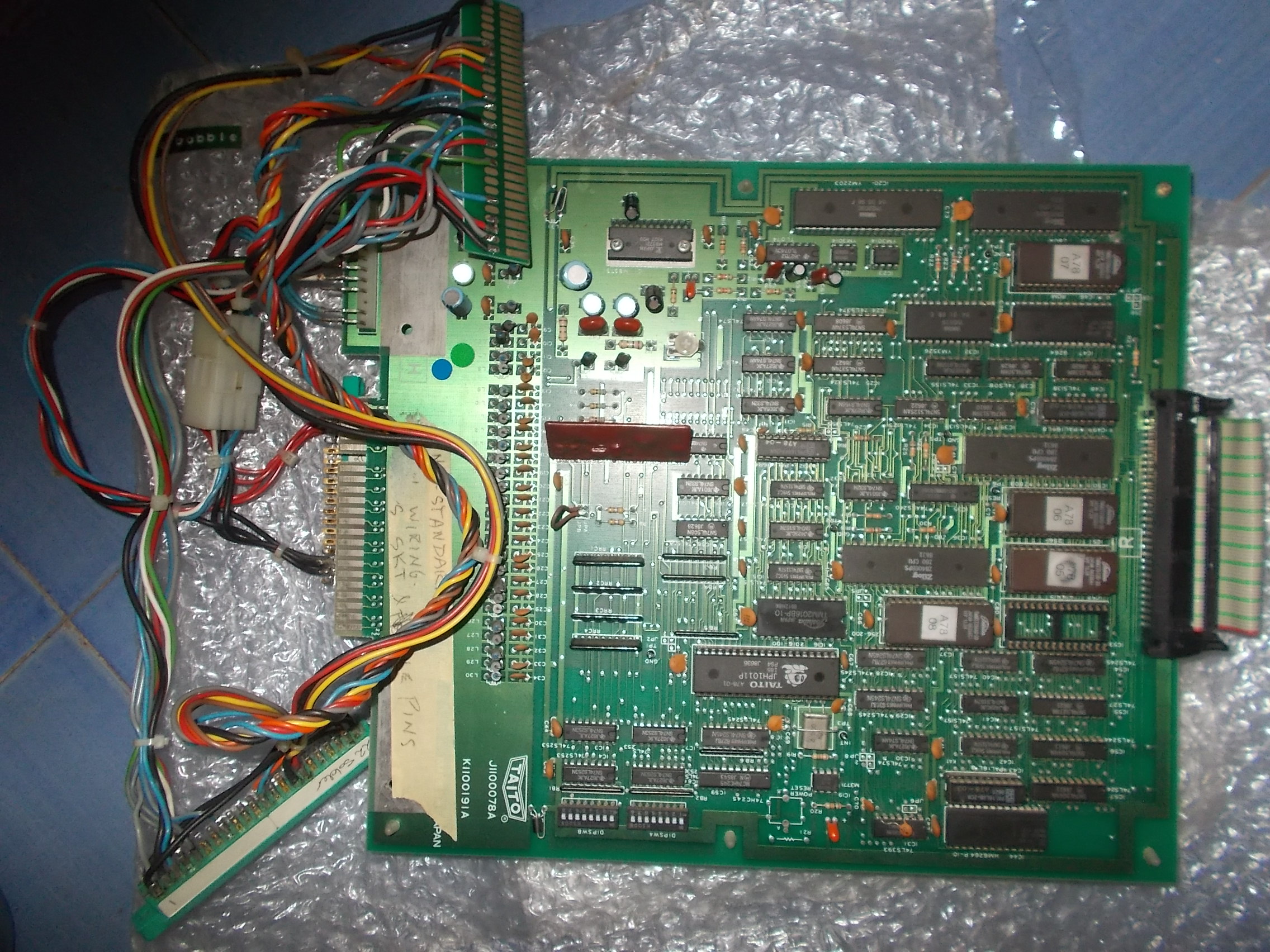
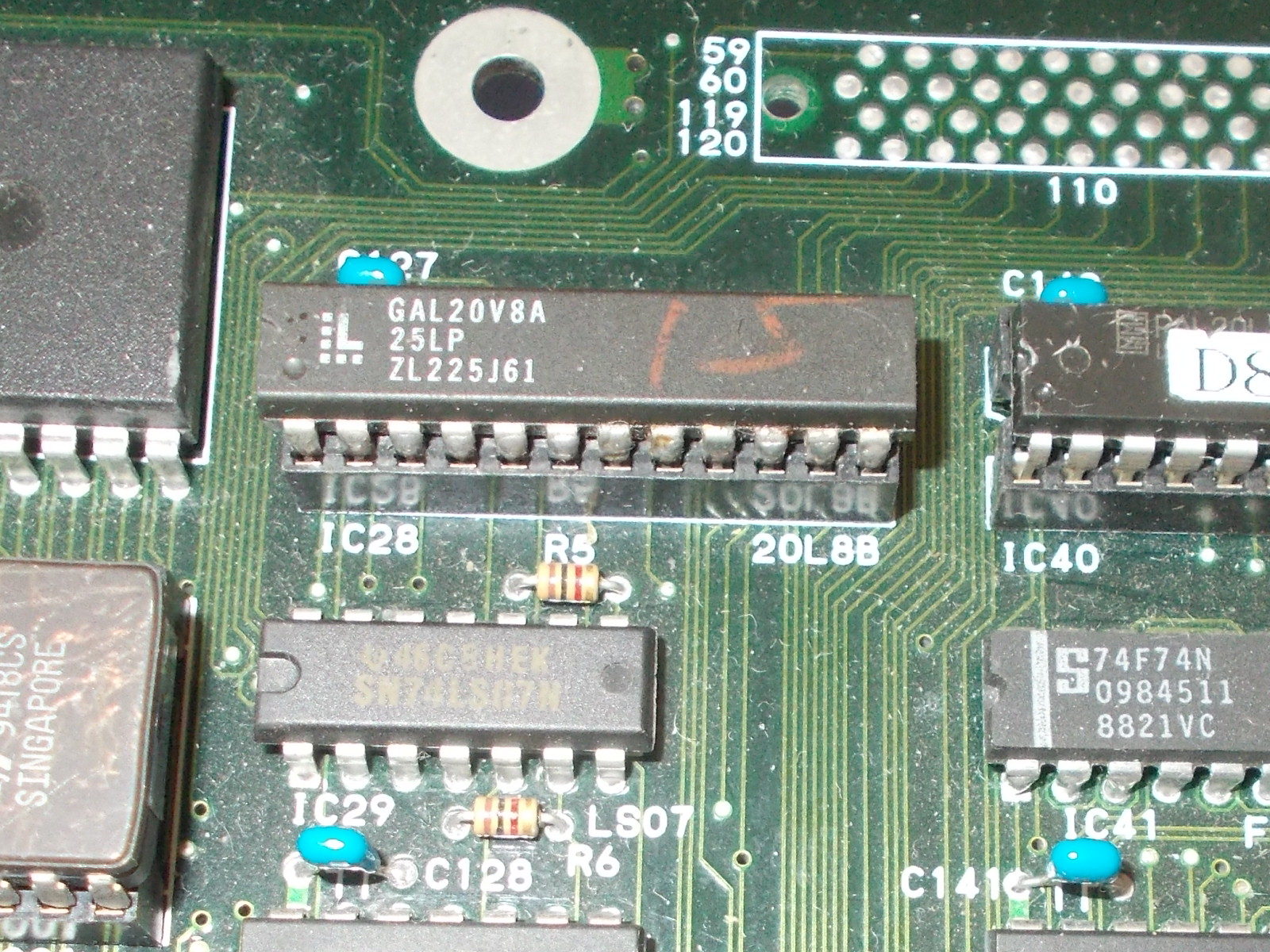
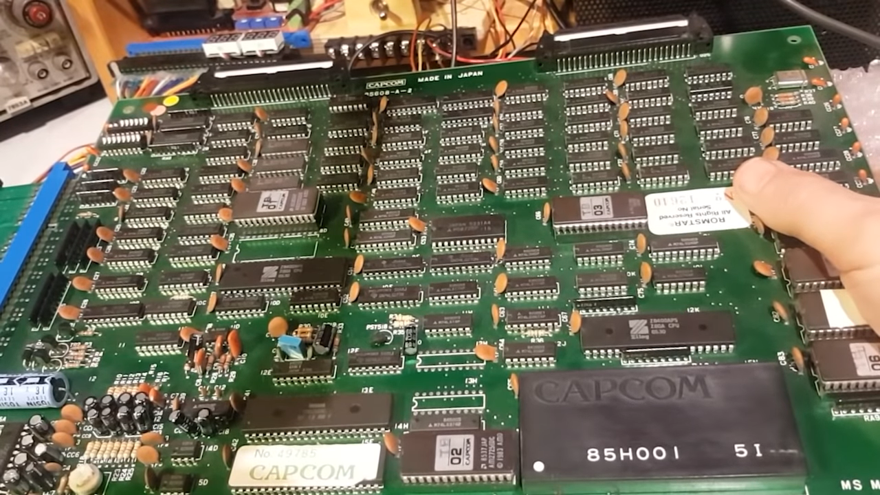
Received for repair from New Zealand this The New Zealand Story PCB (sorry for the wordplay…), the one layer hardware revision :
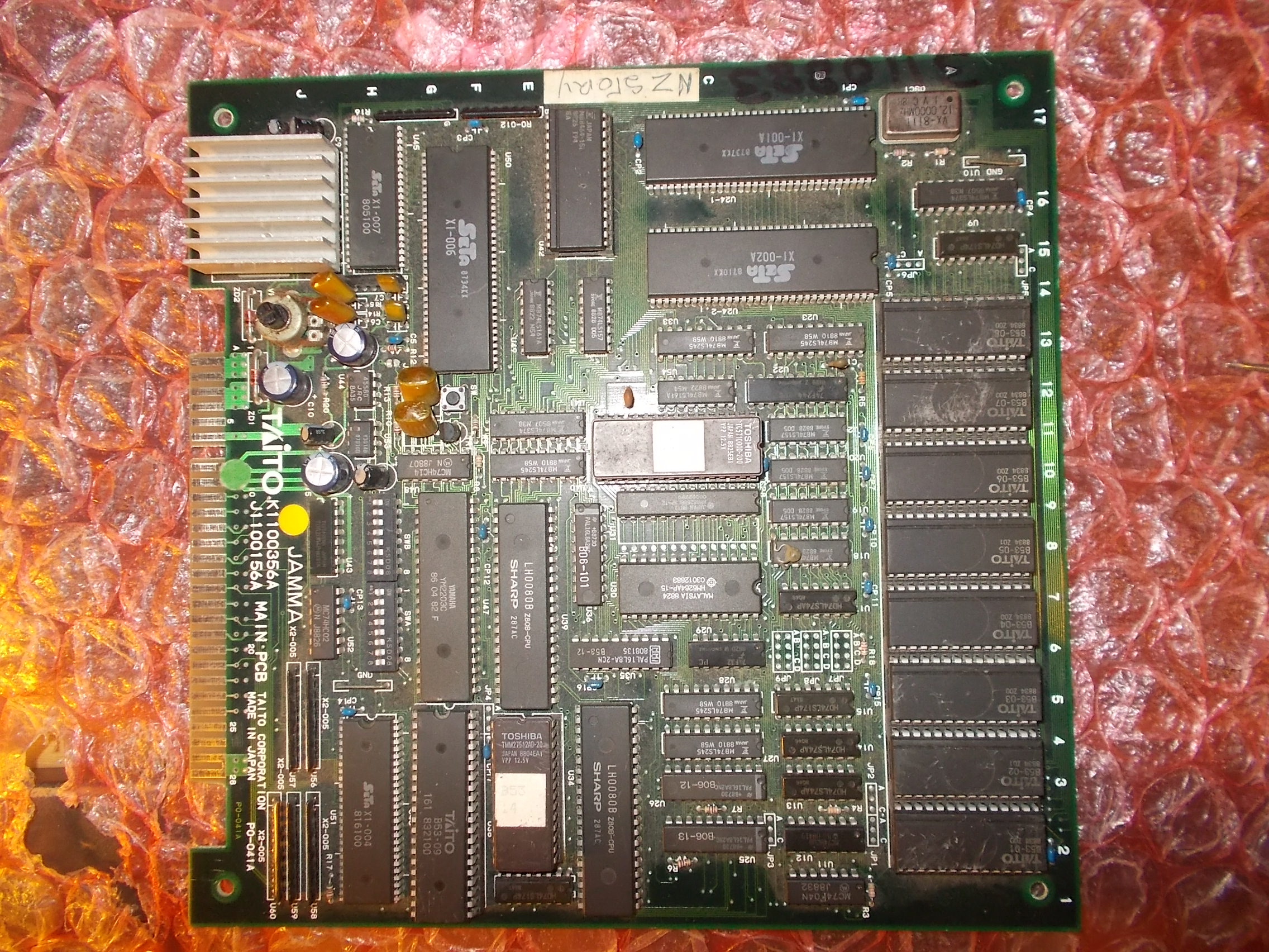
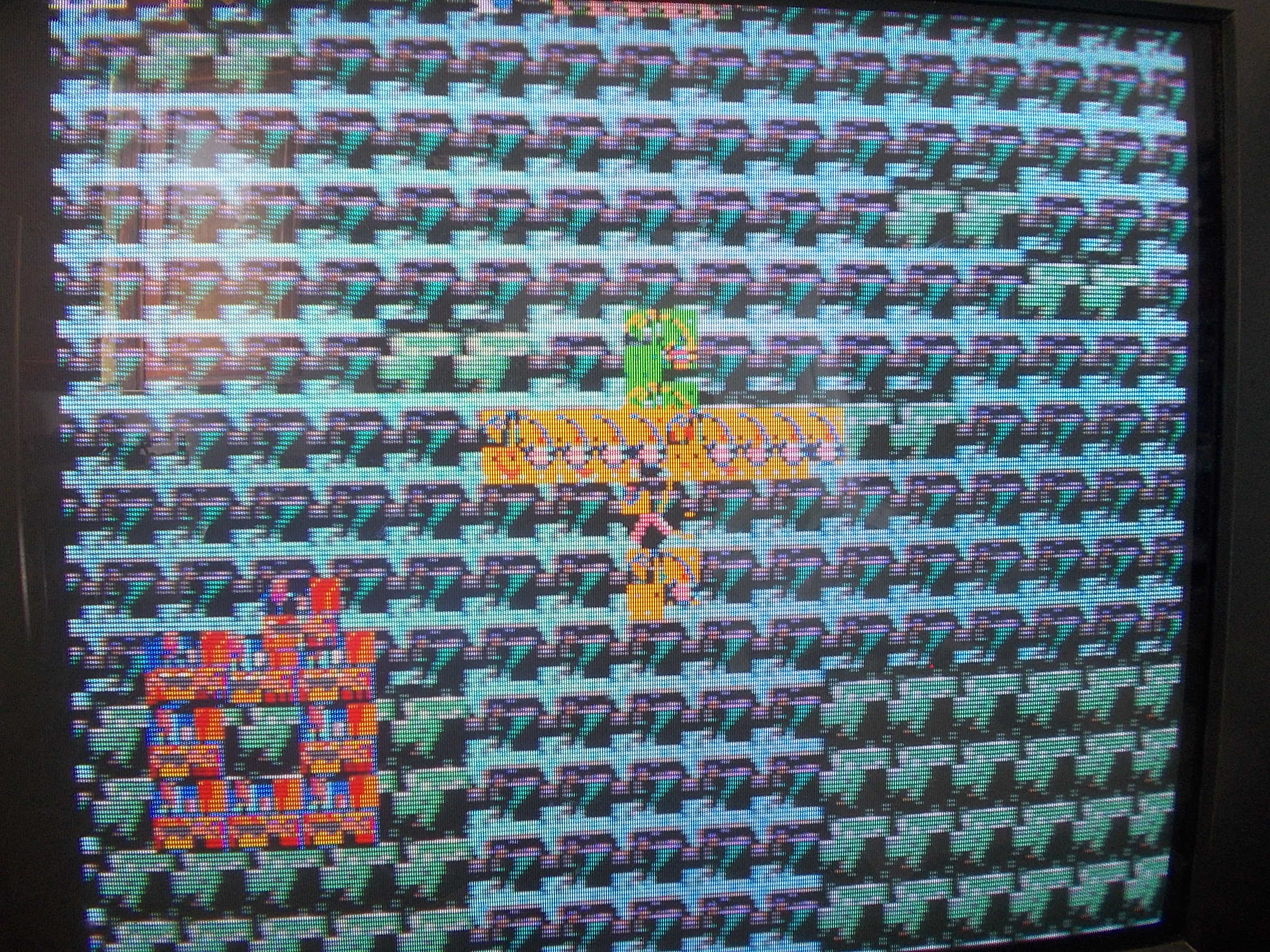
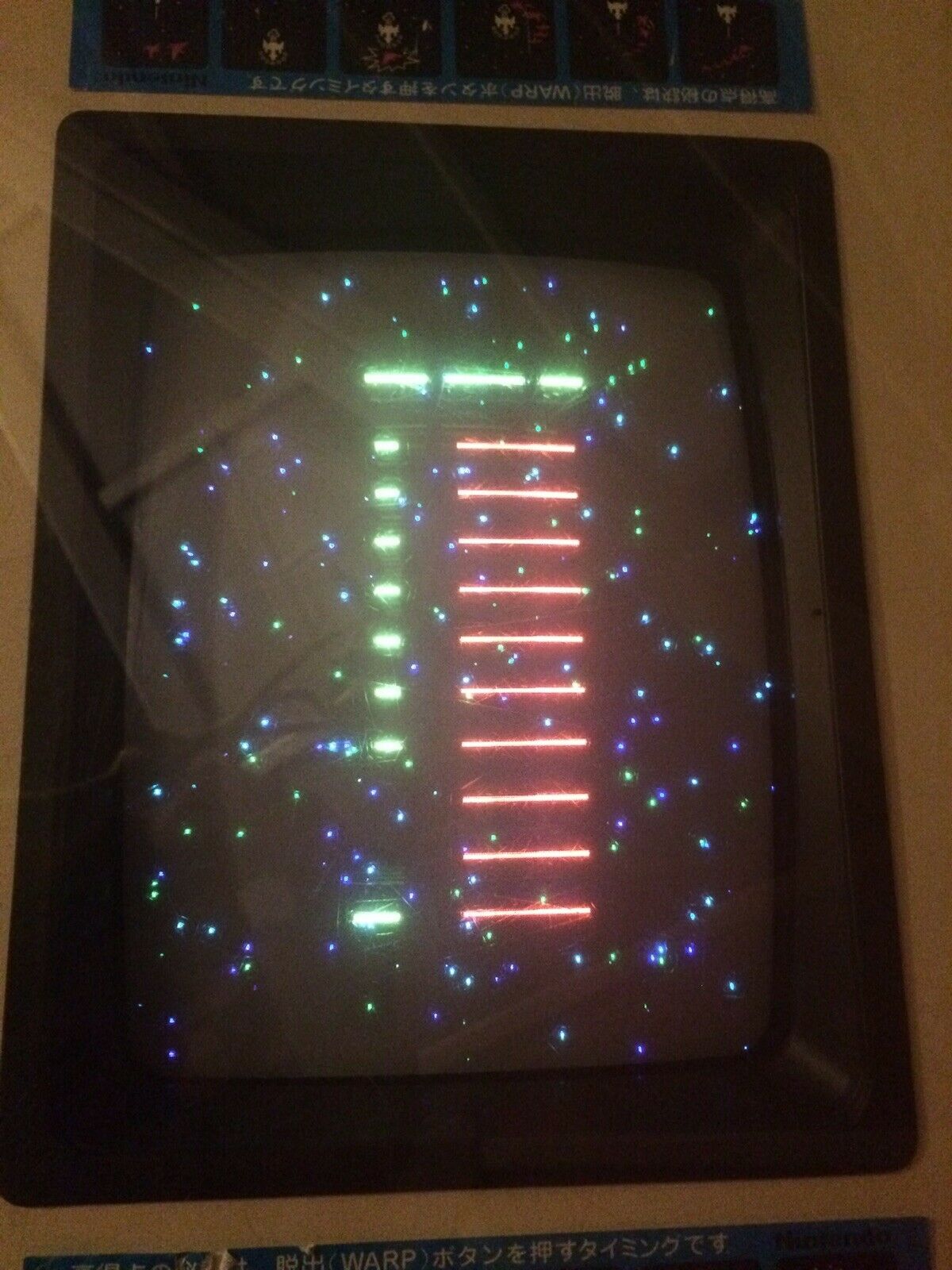
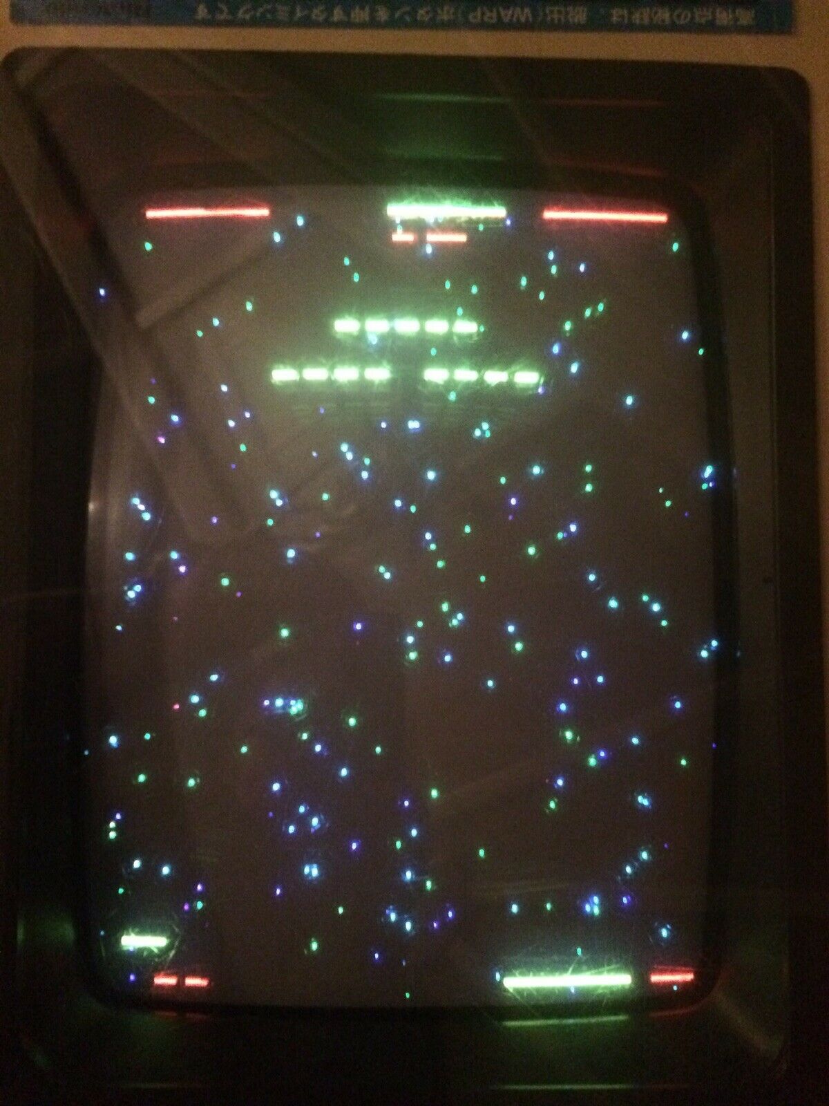
Board booted up but graphics were totally wrong :
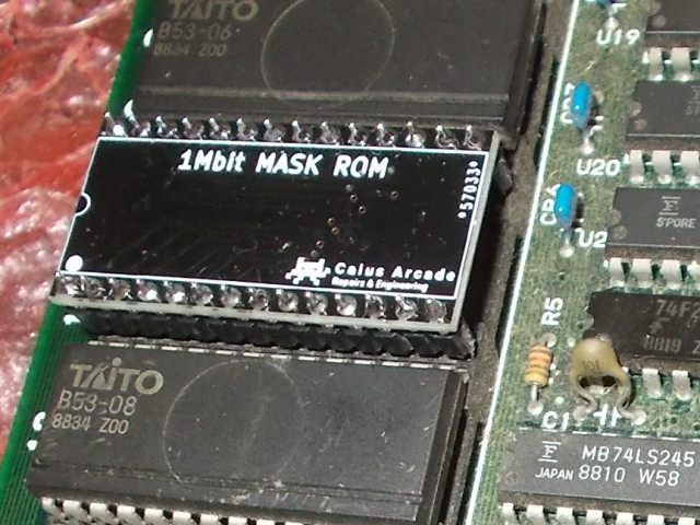
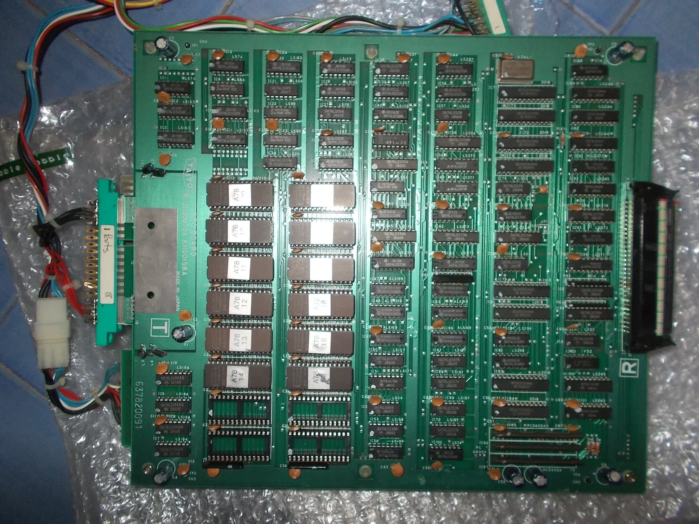
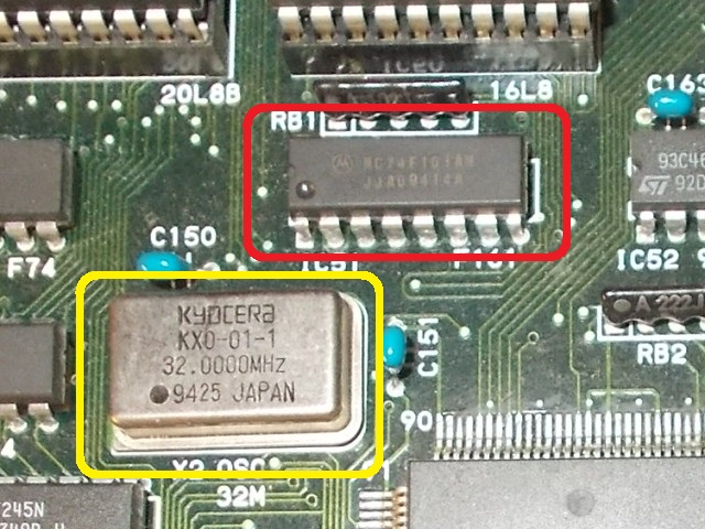
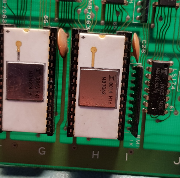
GFX data are stored in eight 28 pin 1Mbit MASK ROMs whose pinout is pretty identical to 32 pin 1Mbit non-JEDEC EPROM (extra pins apart)
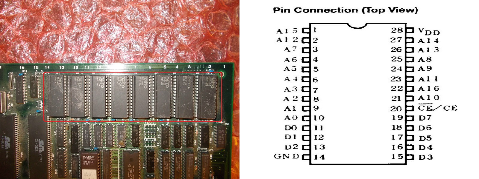
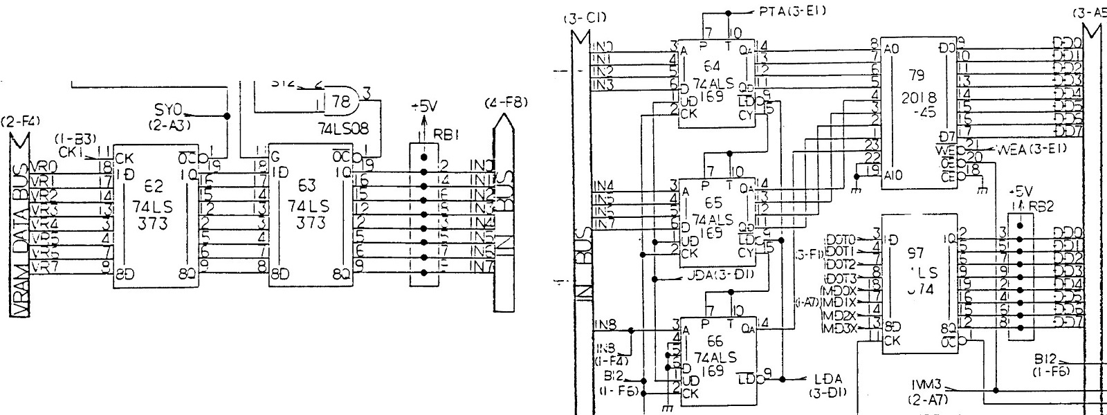
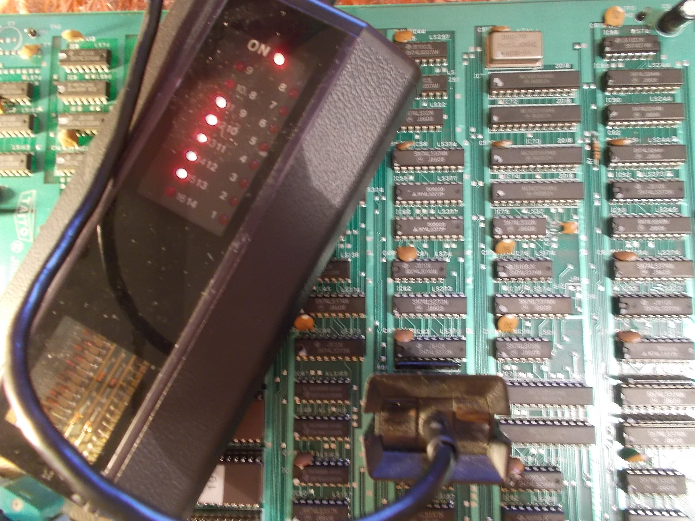
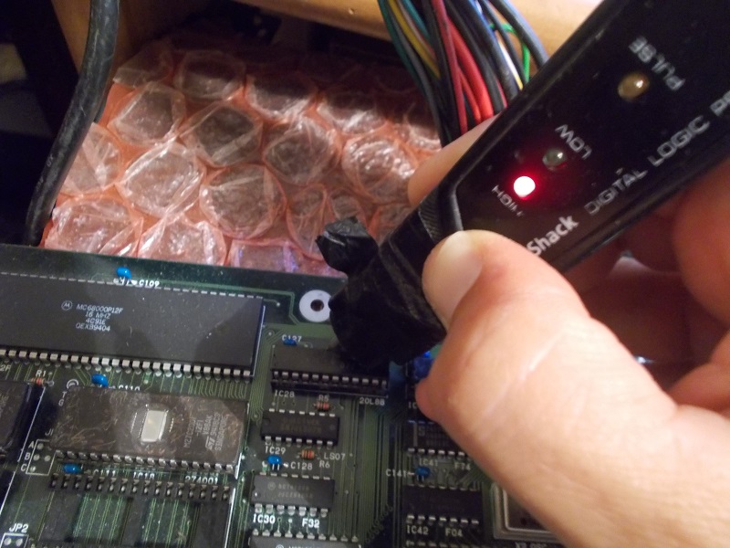
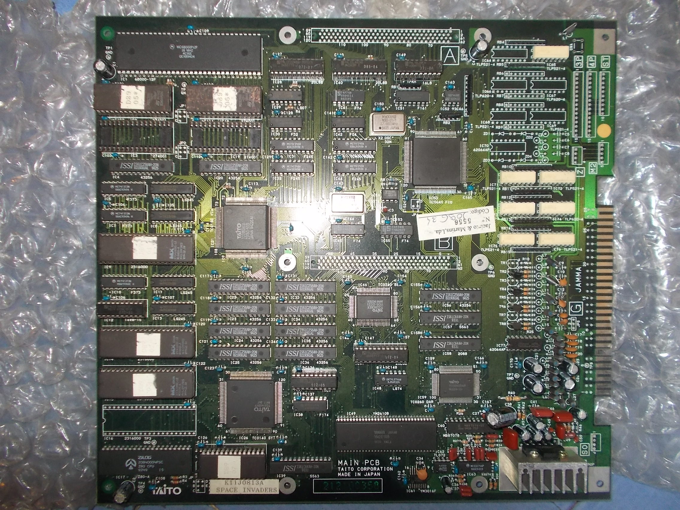
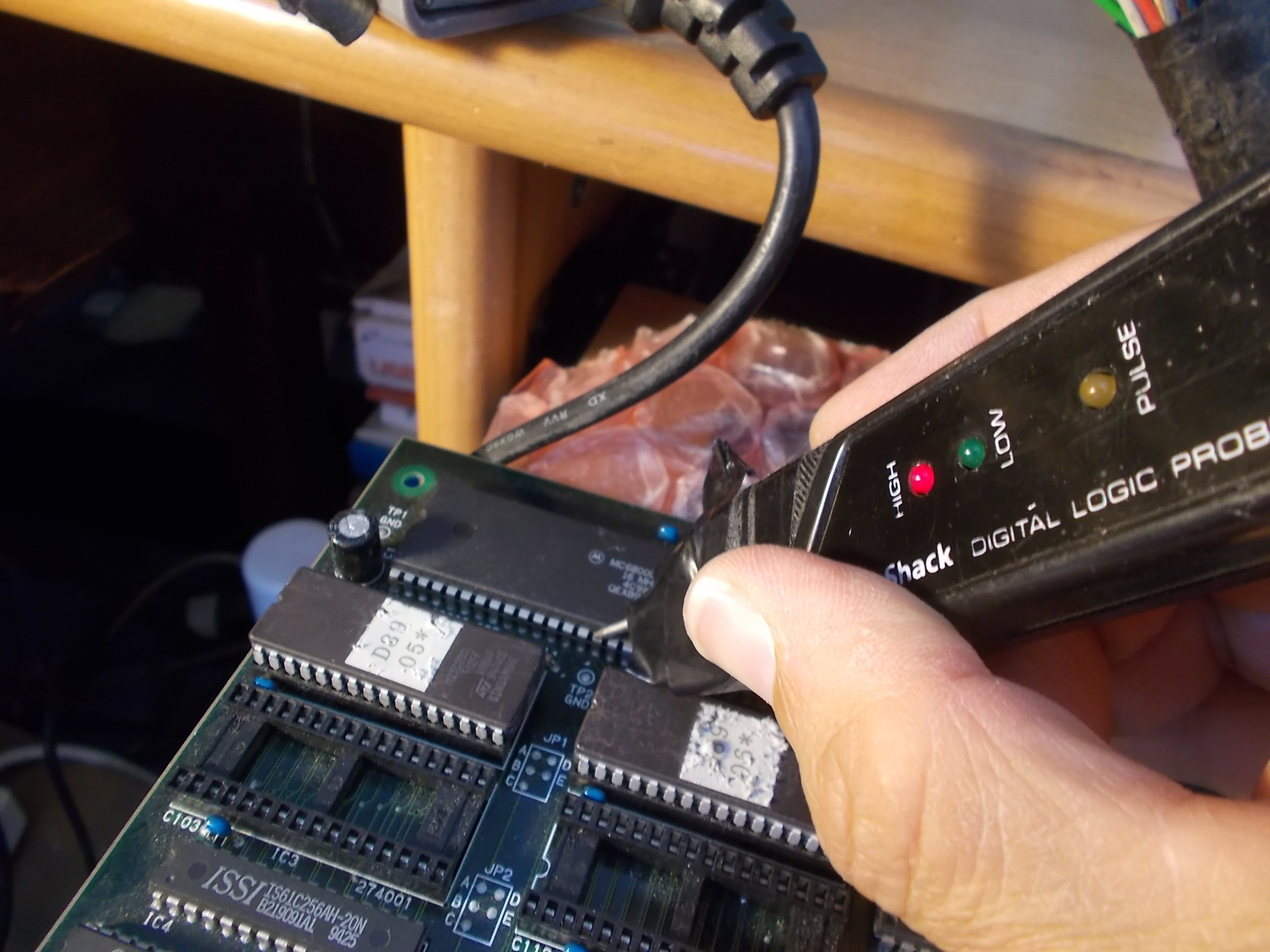
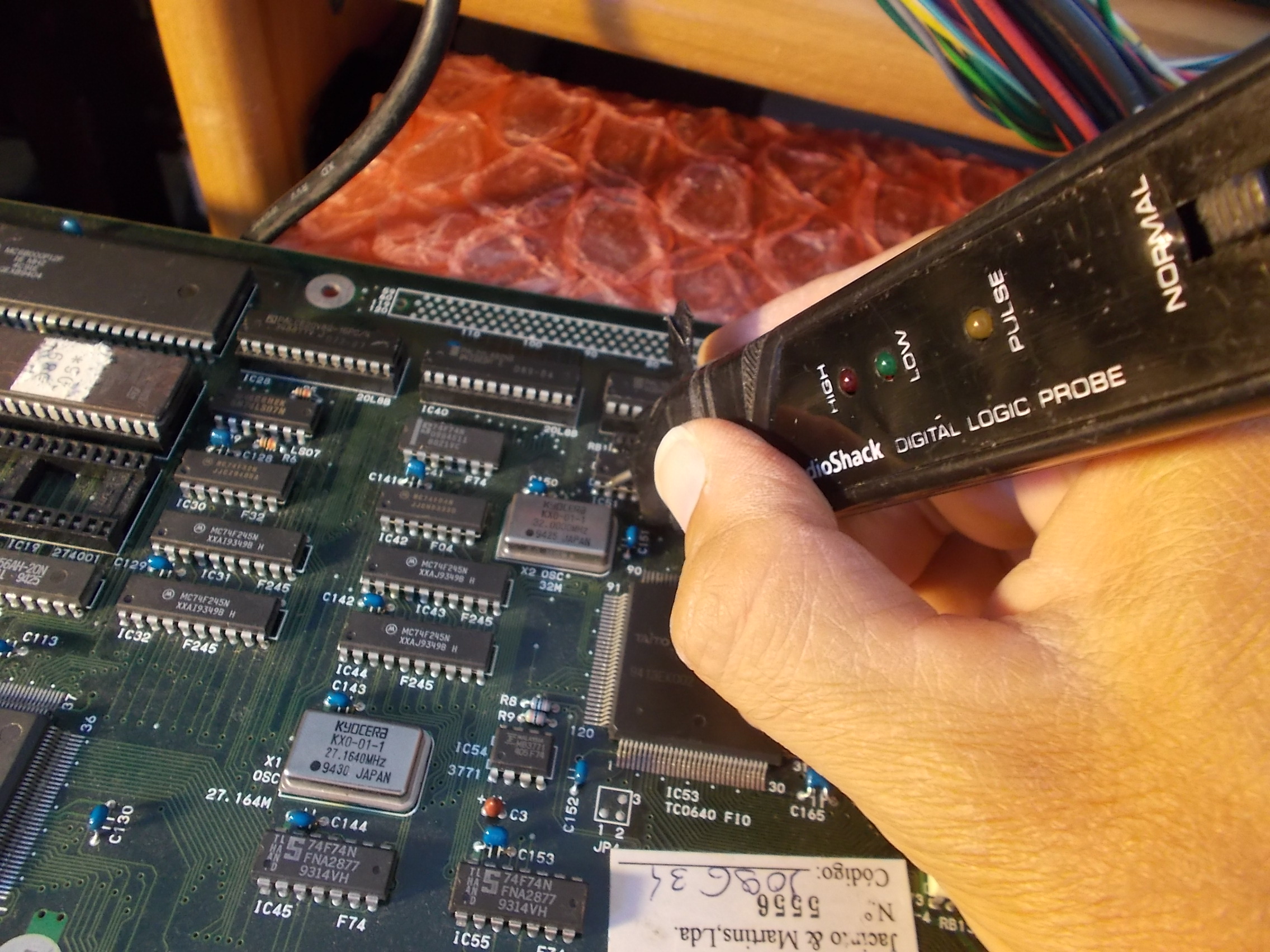
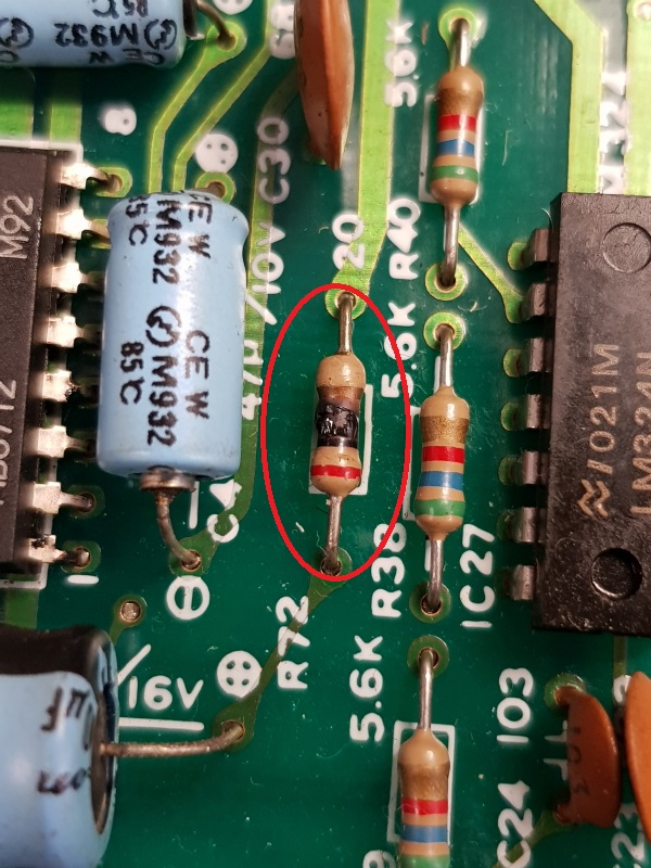
Before dumping them I used my logic probe and found stuck upper address lines (pin 12-13-14-15)
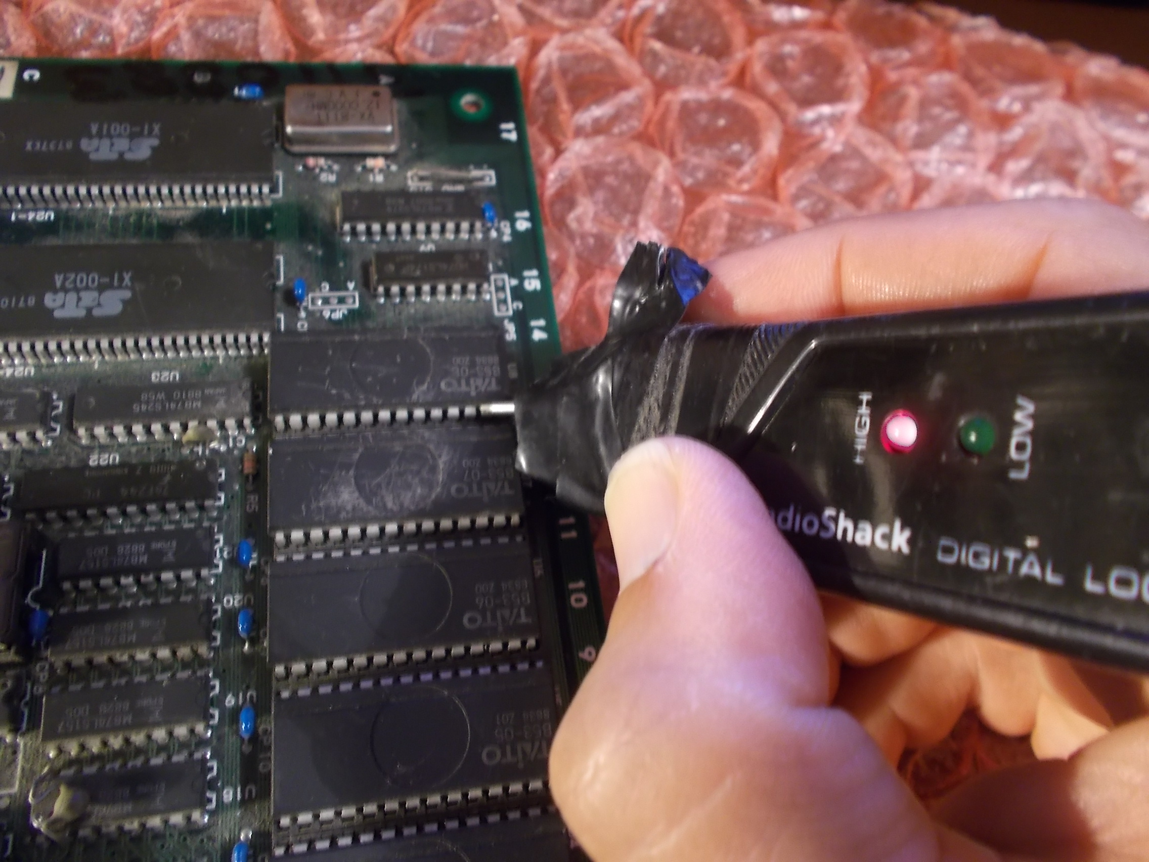
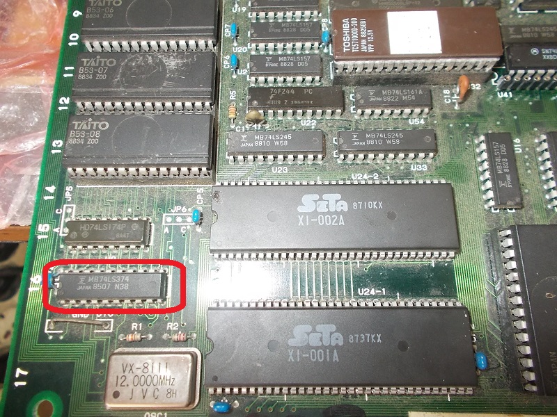
I traced the address lines back to outputs of a 74LS174 @U9 whose inputs were floating, these came from a Fujitsu 74LS374 @U41:
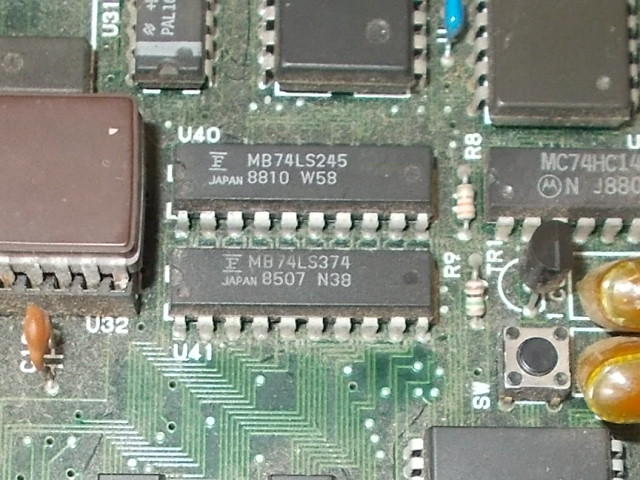
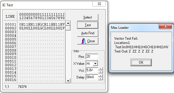
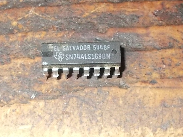
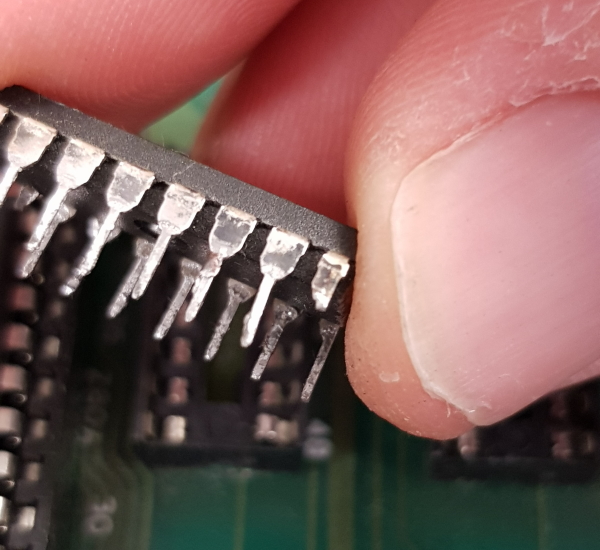
Inputs of it were toggling but all outputs were stuck at undefined voltage level of 1.48V, this is the typical way of failure of Fujitsu TTLs :
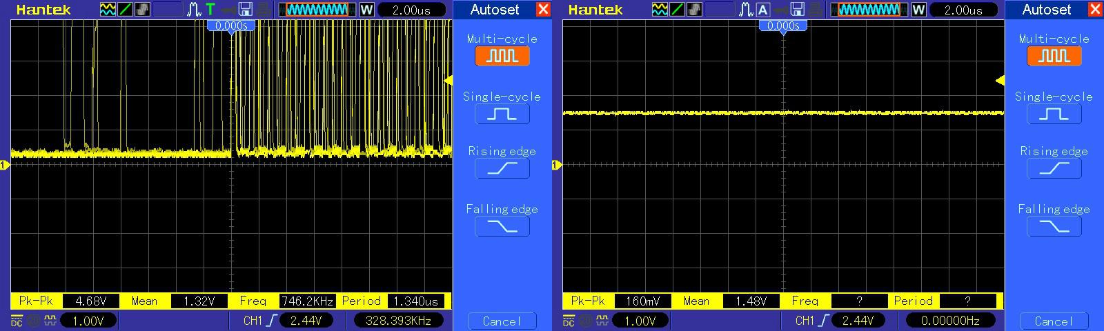
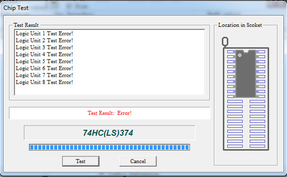
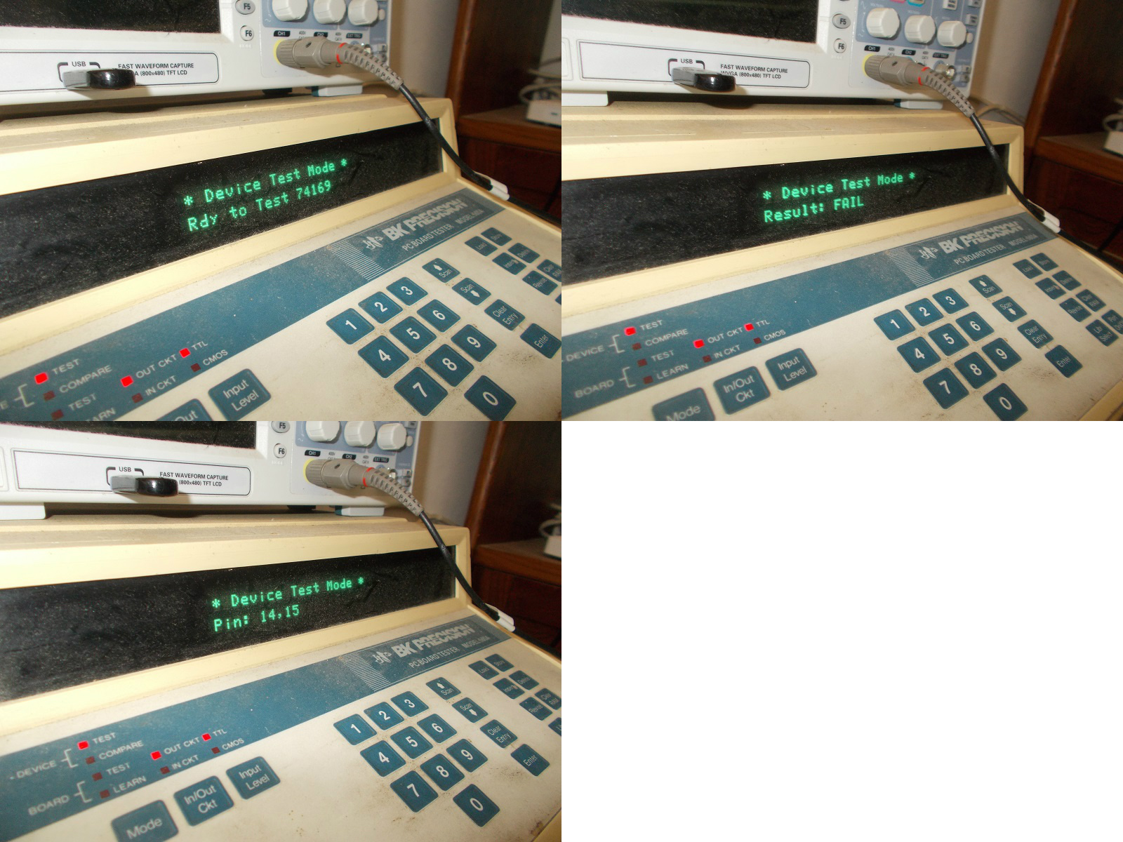
The chip failed the out-of-circuit testing, all outputs were indeed in ‘Z’ (or high-impedance if you prefer) state :
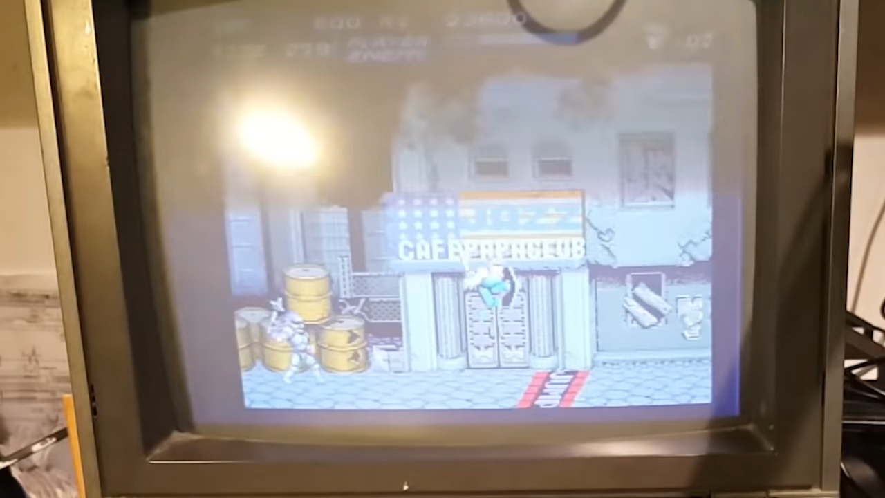
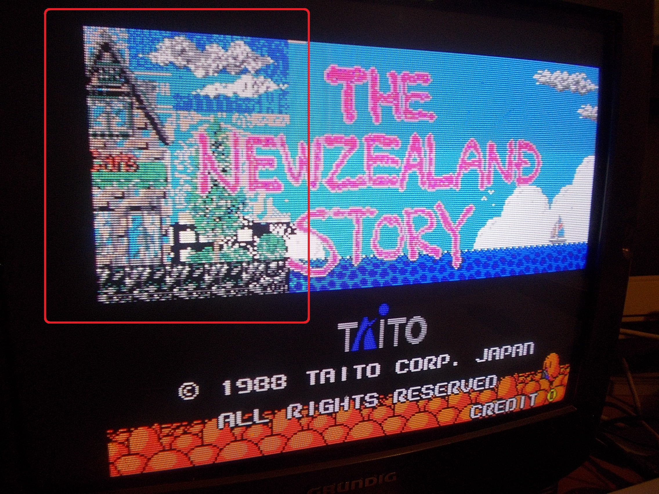
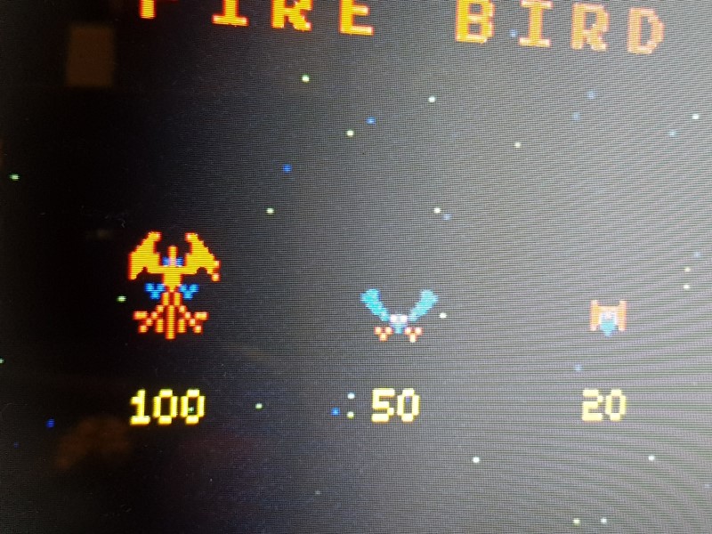
Once replaced the IC the graphics were restored but I noticed some corruption on title screen :
I dumped the 1Mbit MASK ROMs and my programmer complained about the one @U7 :

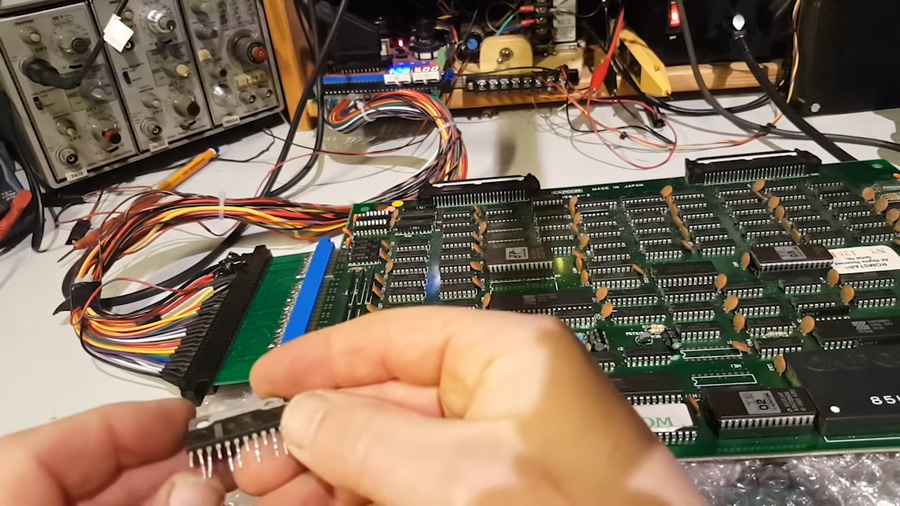
This was a good chance to use one of my adapters I designed some time ago for replacing the 28 pin 1Mbit MASK ROMs with a TSSOP Flash ROM
But suddenly during power cycling the graphics went bad again :
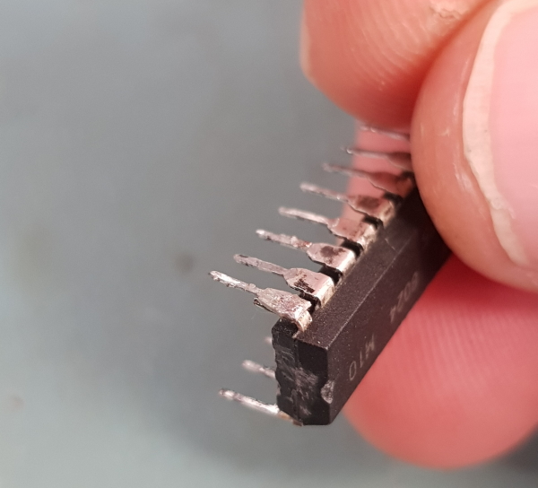
I quickly pinpointed the fault to another 74LS374 @U10 with floating outputs, another Fujitsu one obviously :
Chip totally failed the out-of-circuit testing:
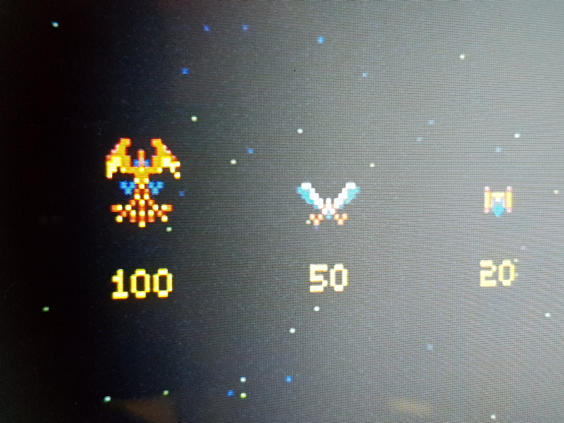
Graphics were now perfect so I started a game but controls didn’t work, the main character of both players moved by itself:
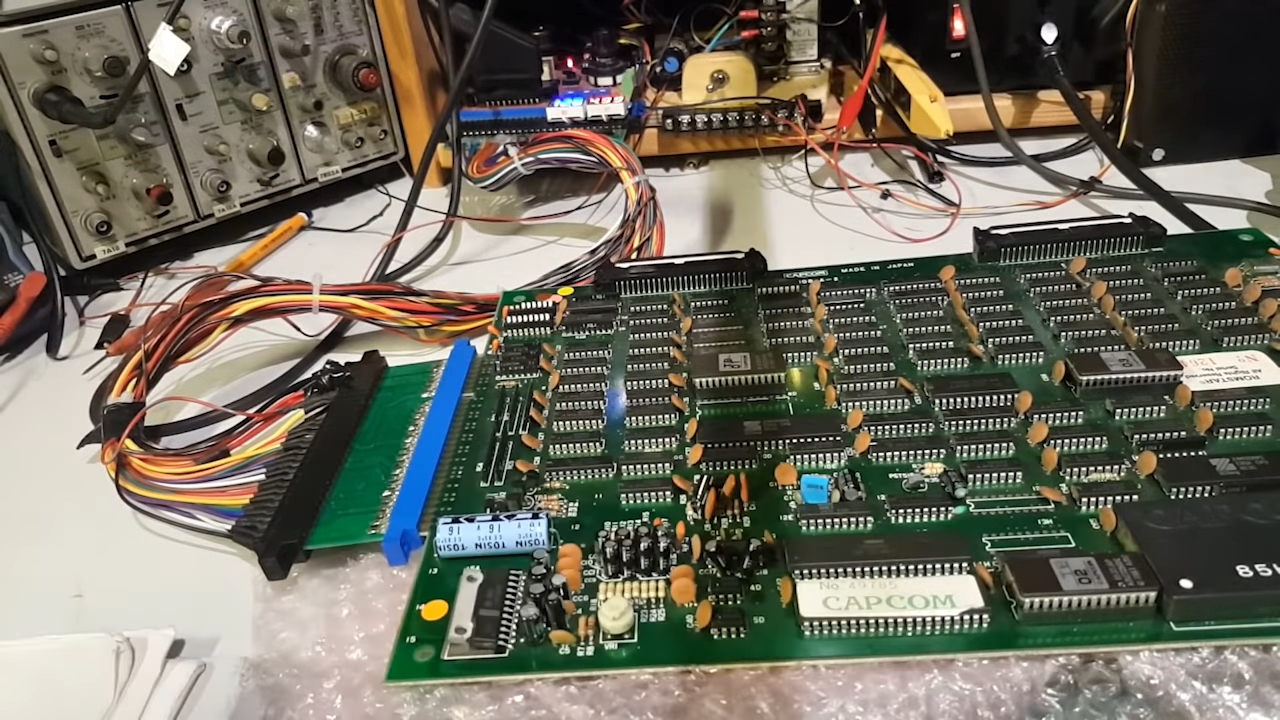
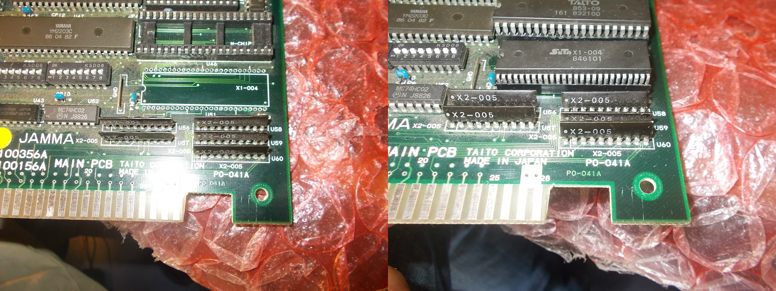
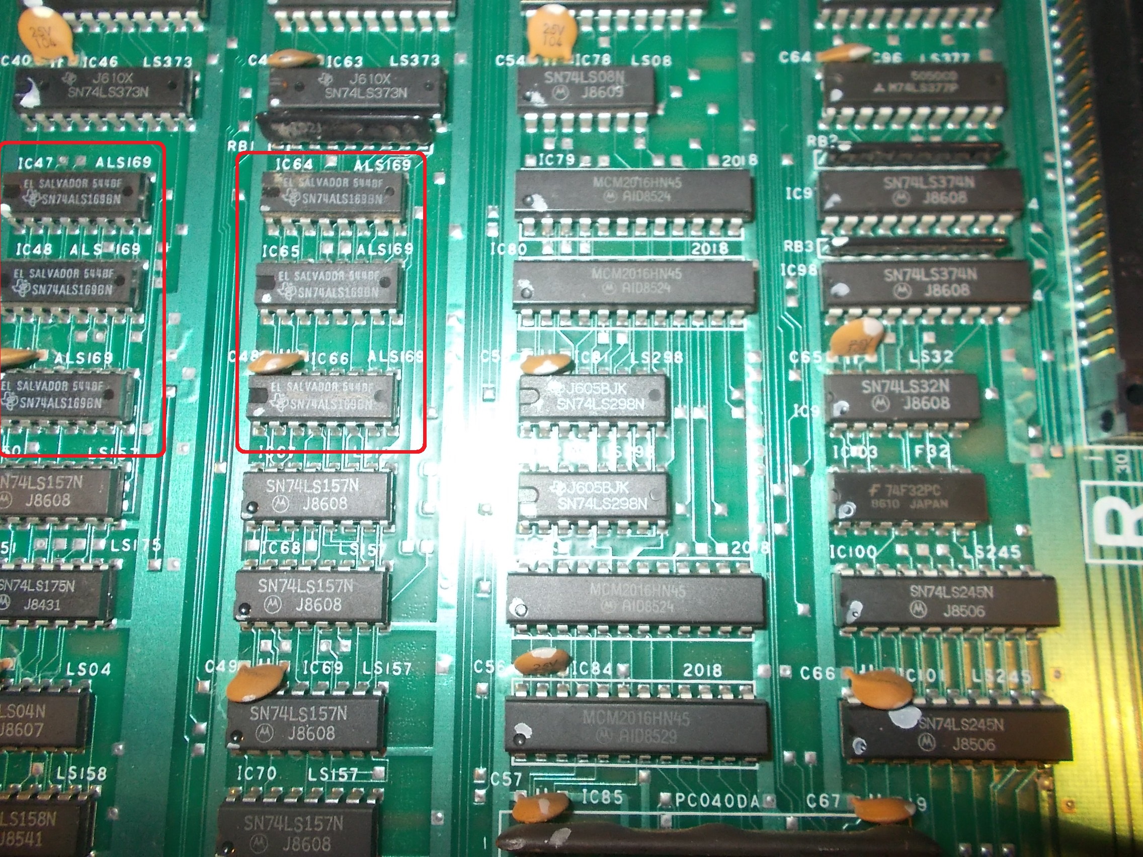
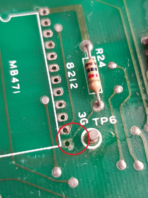
Looking at hardware I figured out the I/O circuit.The inputs from JAMMA connector go to some custom resistor arrays marked ‘X2-005’ and then signals are routed to a 52 pin SDIP custom chip marked ‘X1-004’ that handles them :
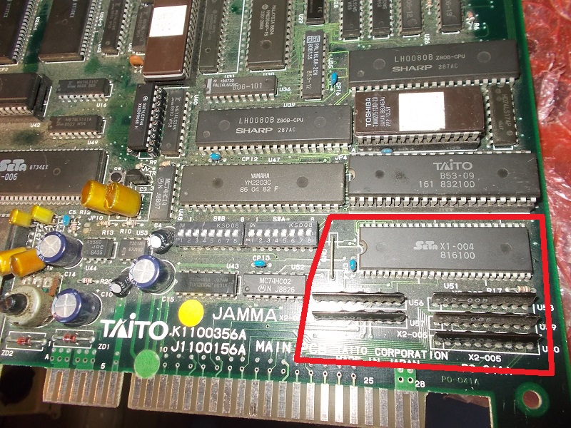
Resistor arrays did their job by pulling-up the signals and then routing them to the custom so most likely the ‘X1-004’ was bad.I played the card of replacing it but I had to struggle before finding a good spare as it seems this custom is quite prone to failure.I tried two donor parts but they were faulty until I caught the good one:
This fixed the controls and board completely.Repair accomplished.


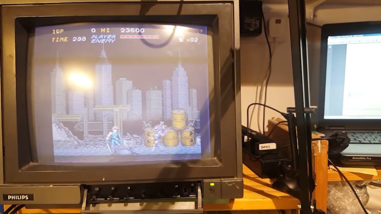
 So I fired up the board and it booted up just fine. However there was absolutely no sound coming out.