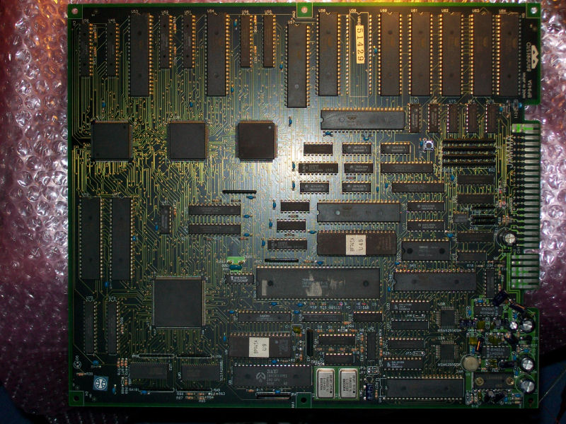
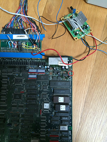
My friend ‘mastercello’ sent me this Donpachi PCB for a repair:
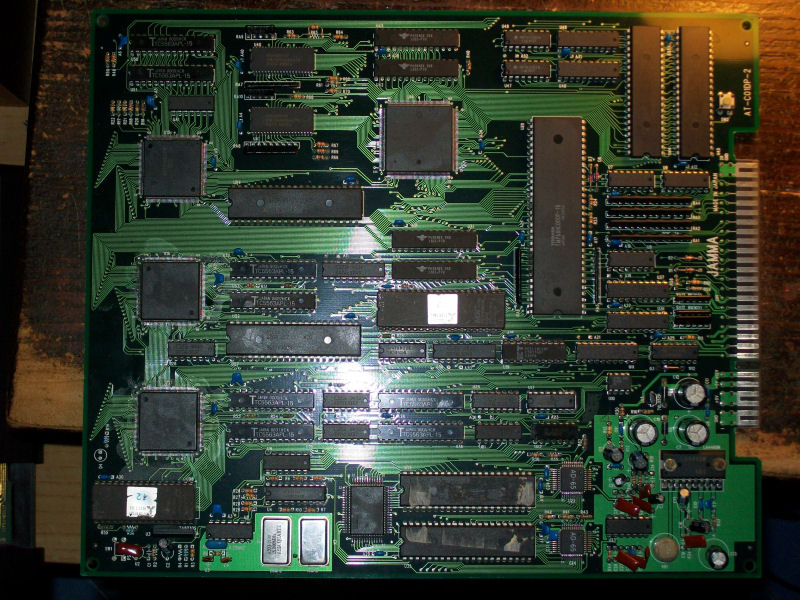
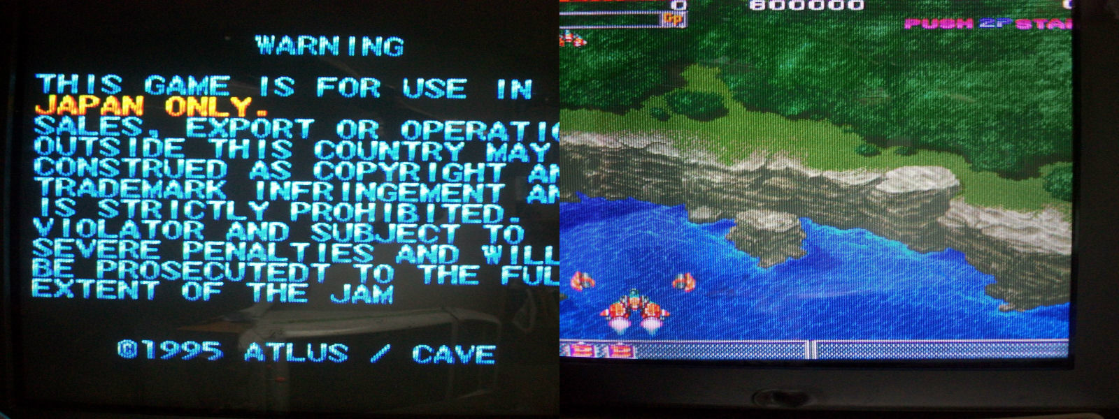
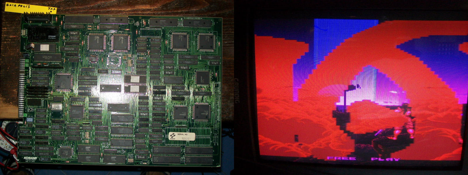
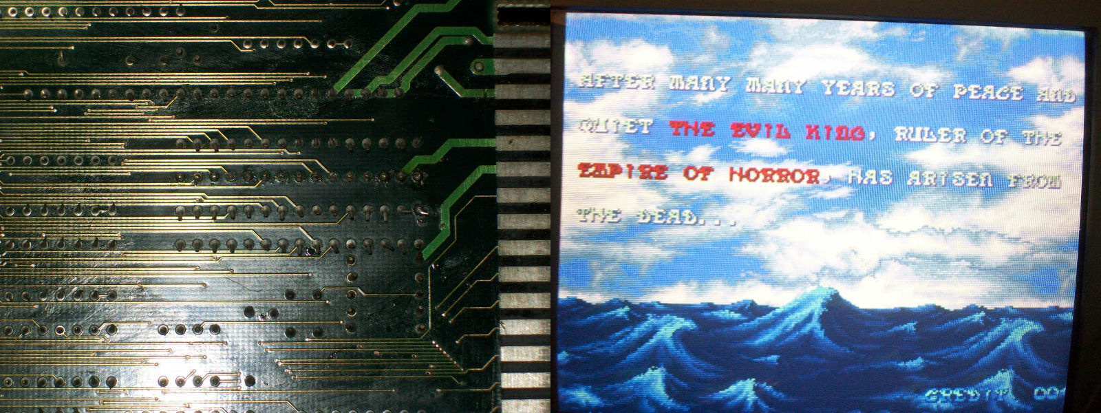
The board was in good shape but had a GFX issue where background layer was partially missing with lines across it:
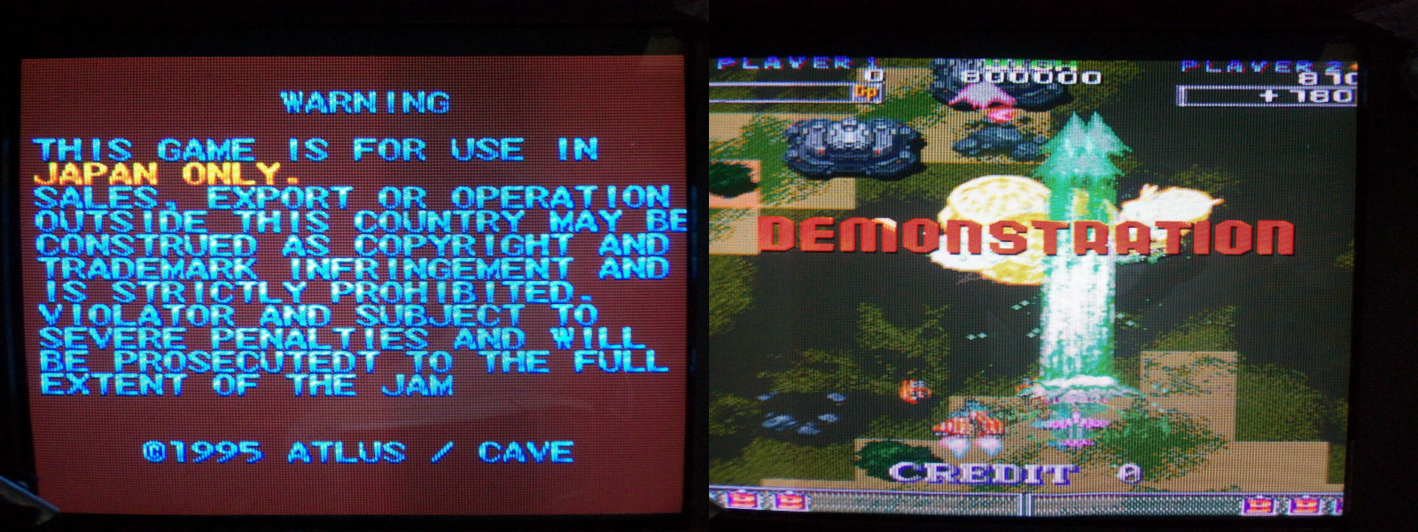
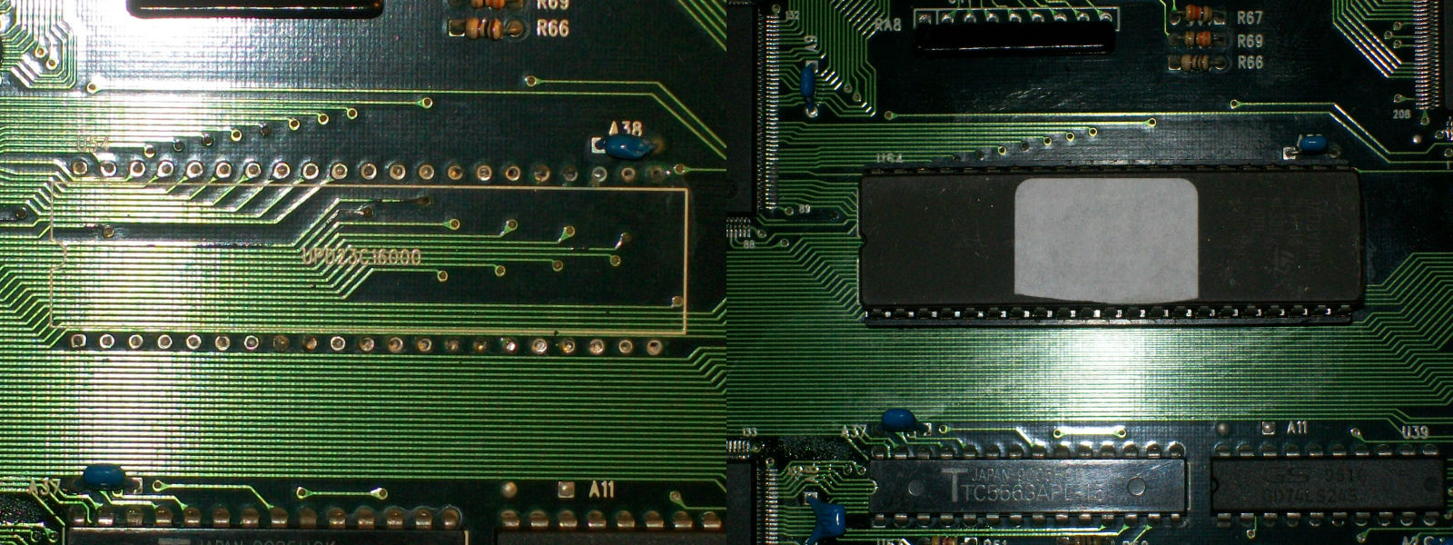
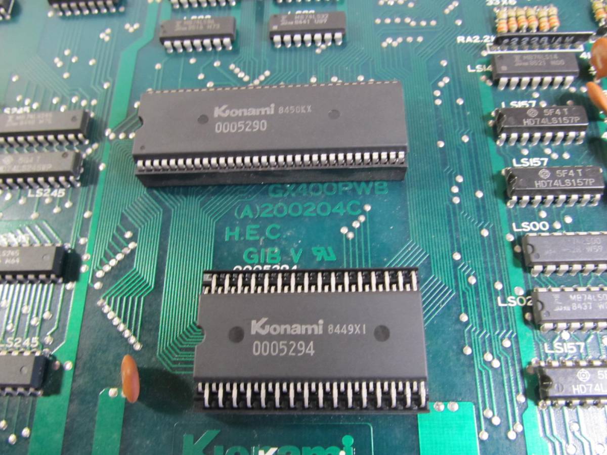
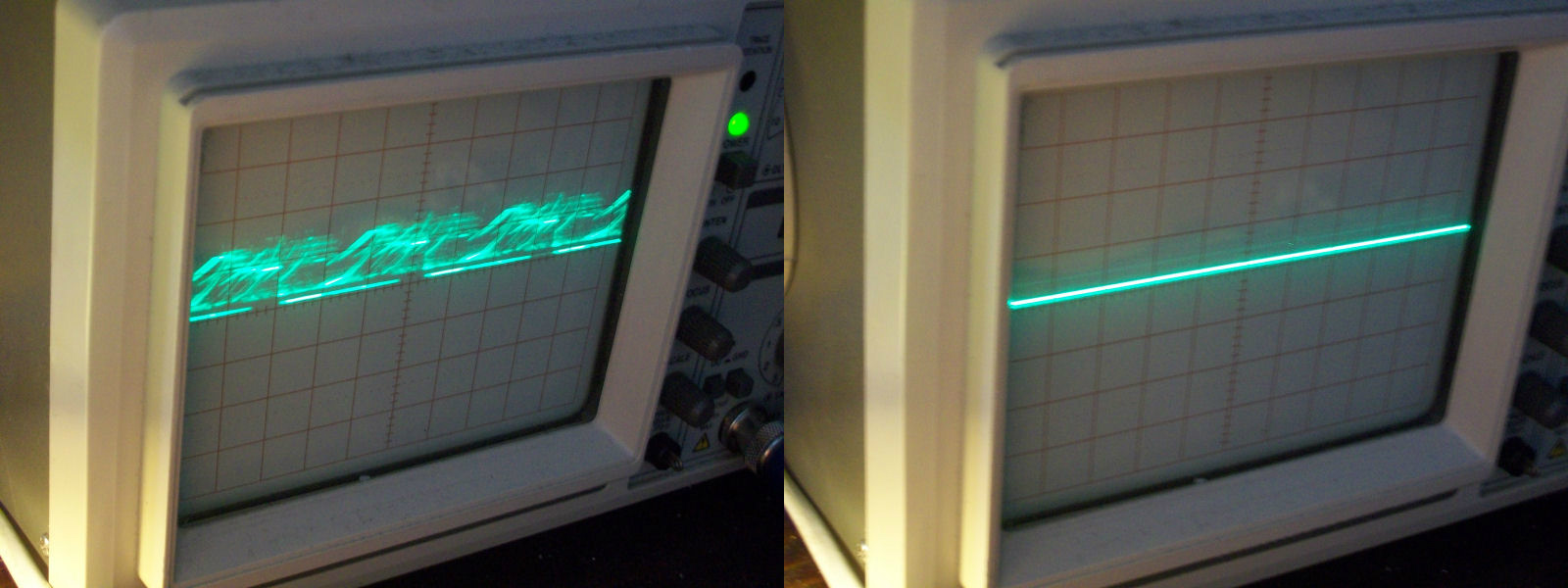
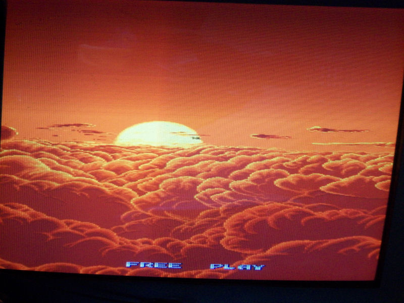
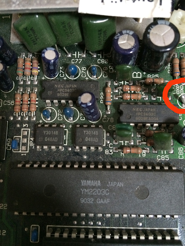
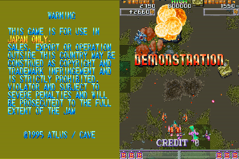
Studying the hardware and with help of MAME I could identify the devices containing the data of the two background layers, they are two 42PIN 8 Mbit MASK ROM @U54 and U57.Probing them with a logic probe I found that the one @U54 has all its data lines stuck LOW or HIGH, also the two control lines /CE and /OE were stuck LOW though they were properly connected to a near ASIC which generates these signals.Obviously this was totally abnormal.As confirmation of my theory I was able to reproduce ths issue in MAME using a dummy ROM file of the background layer data instead of a good one:
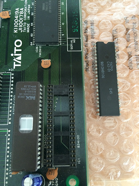
This was enough to convince me to desolder the MASK ROM and read it in my programmer resulting in an empty dump.Direct replacement for this 8 Mbit 42PIN MASK ROM is a 27C800 EPROM though the silkscreening under the chip sais ’23C16000′:Fitted a freshly programmed device restored graphics completely.