My friend ‘robotype’ sent me some boards for a repair.I hope this log will the first of a long row! 🙂
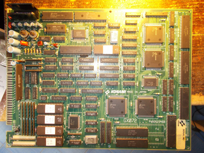
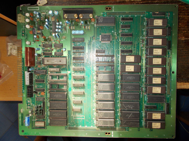
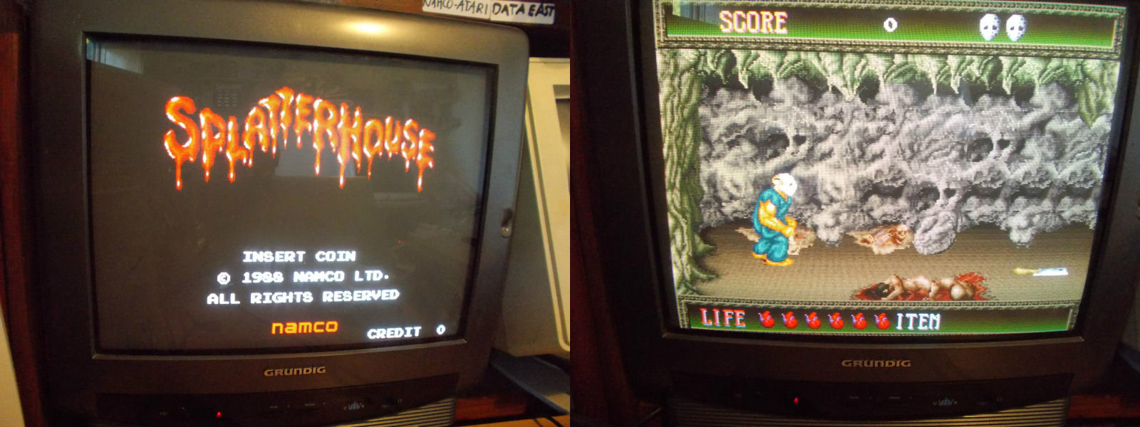
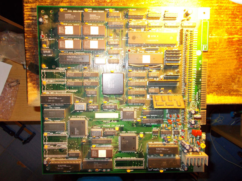
Let’s start with this Jigoku Meguri (the Japanese version of Bonze Adventure) :
 all
all
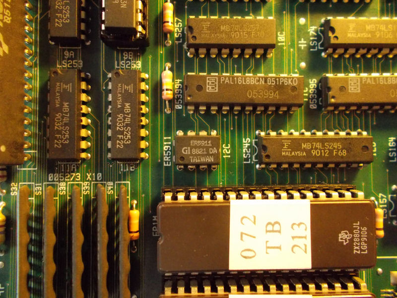
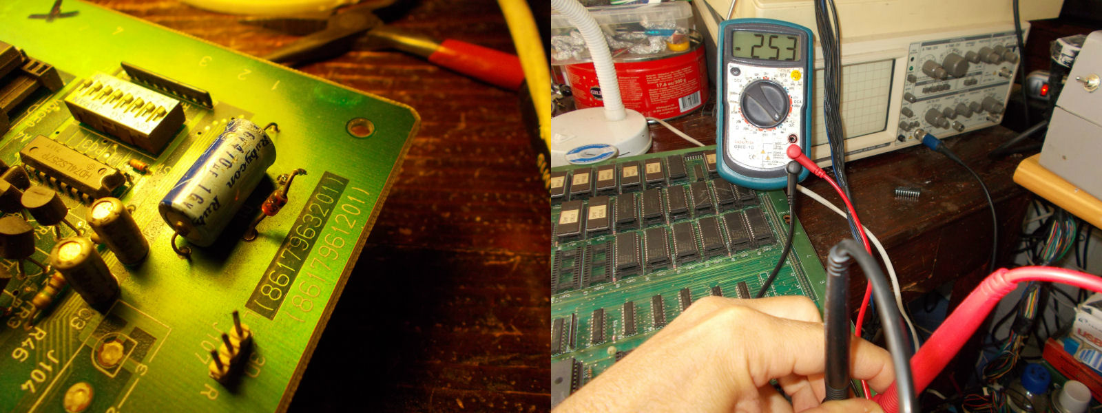
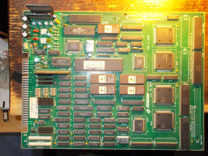
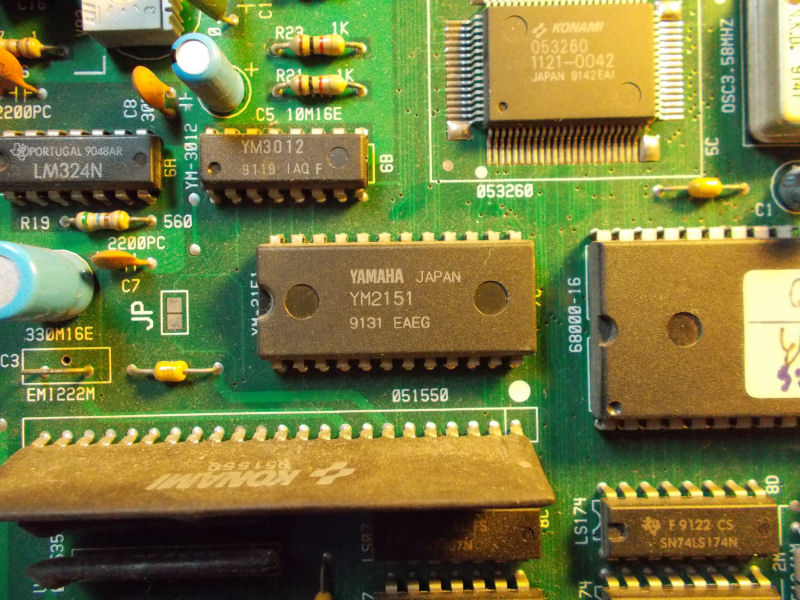
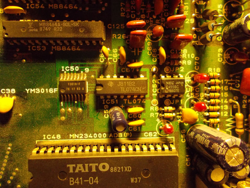
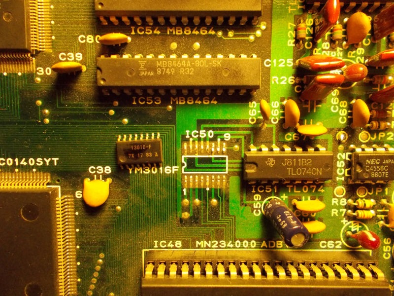
Board played fine but was silent, no audio at all.Digital part of circuit was fine, Z80 CPU was active and healthy so the fault had to be in the analog section.Main amplifer was good producing some noise when I put my fingers on its pins.Other component involved in analog section were a YM3016 DAC , a couple of TL074 and a uPC4556 OP-AMPs:
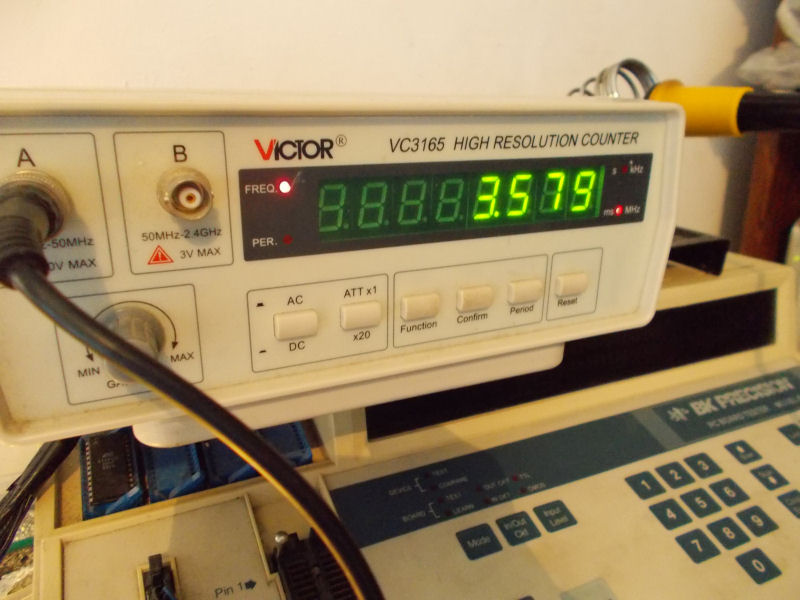
As usual I went to probe the analog output (pin 13) of the YM3016 DAC and sound was present although scratchy and distorted:
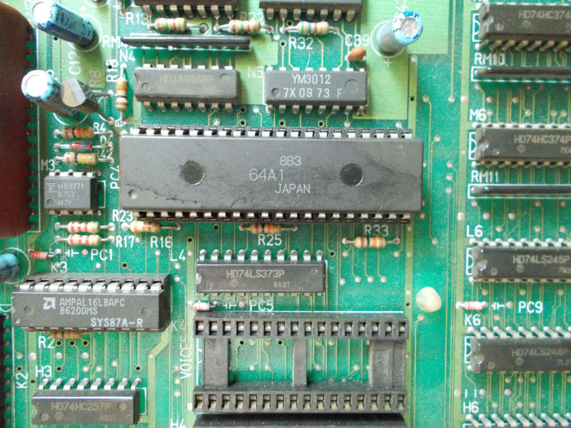
So I decided to replaced this DAC :
In this way the sound from it was fine:
but board was obviously still silent.Following the path of the signal I came to the near uPC4556 OP-AMP.Sound was still present on its inputs not nothing came out from outputs.I replaced it with a compatible LM358 and this restored sound.End of job.