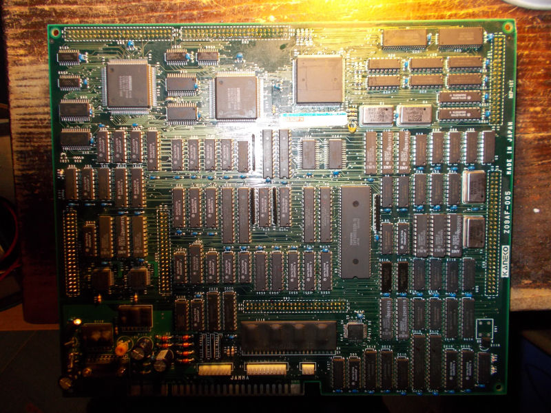
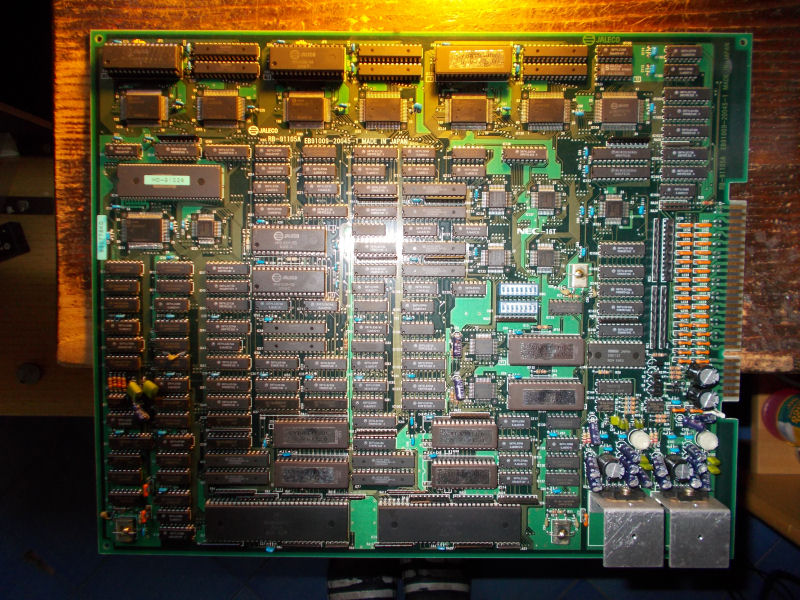
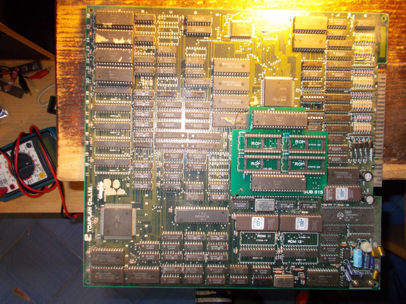
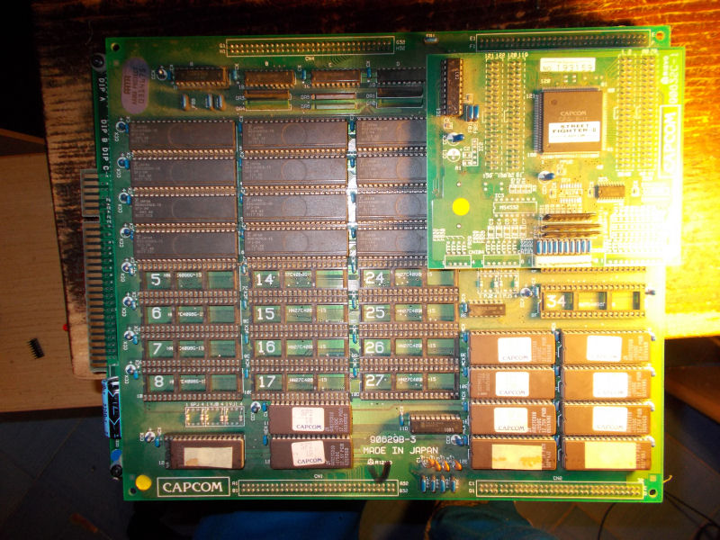
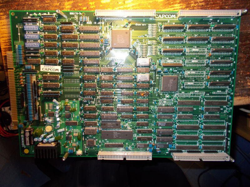
I got this CAPCOM CPS1 A-BOARD (the old hardware revision) from my friend Joachim for a repair:
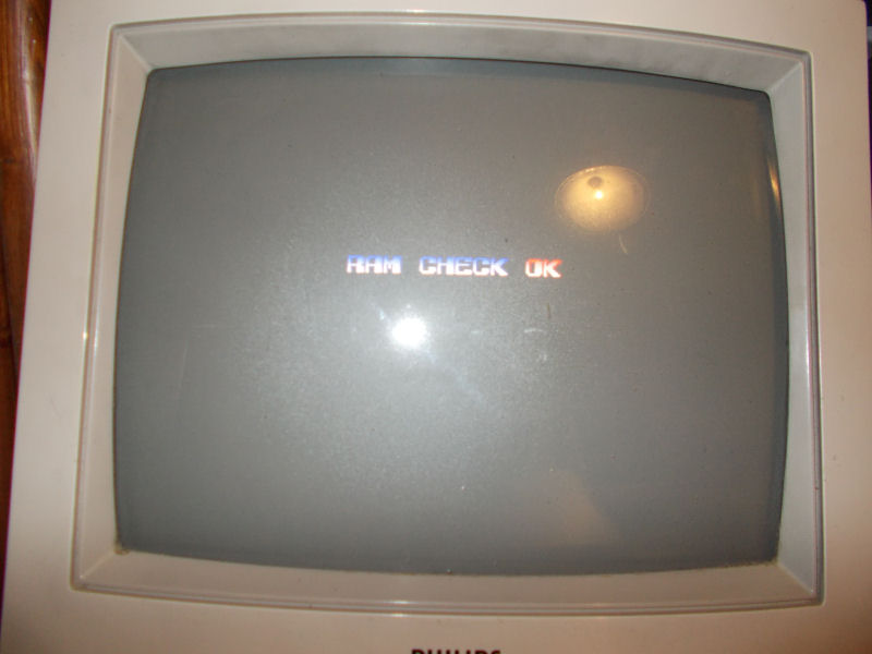
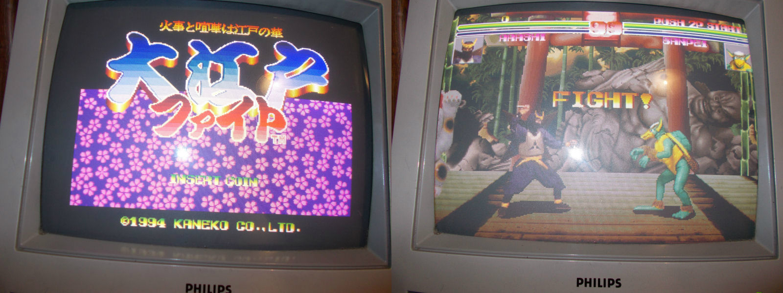
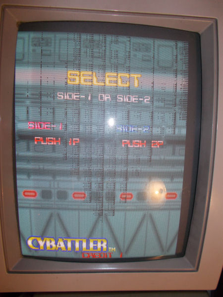
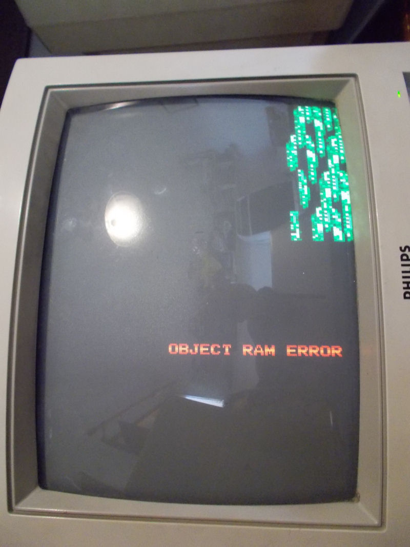
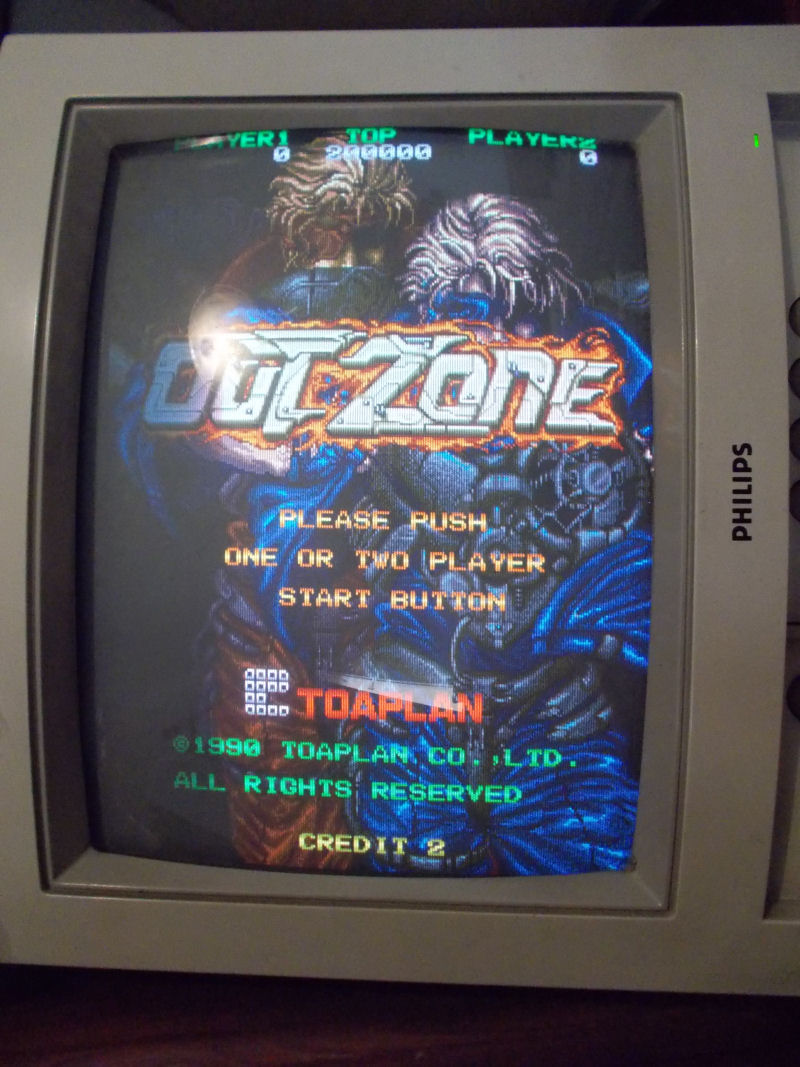
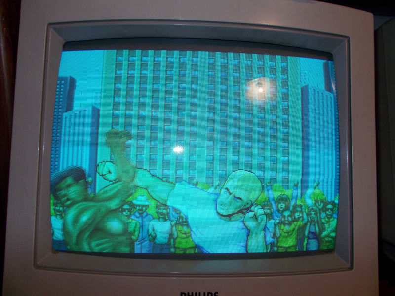
He said me that board had some input problems.This was confirmed once I powered it up since most of player 1 and 2 controls were irresponsive but, after few times I cycled power, suddenly the board lost the red color:
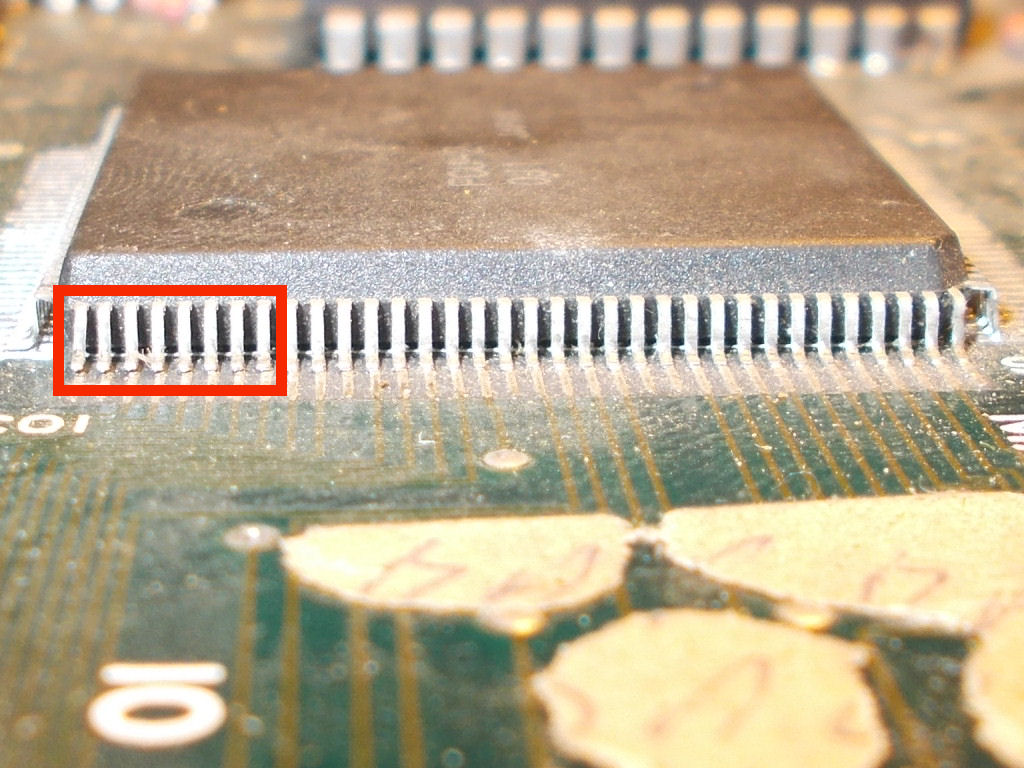
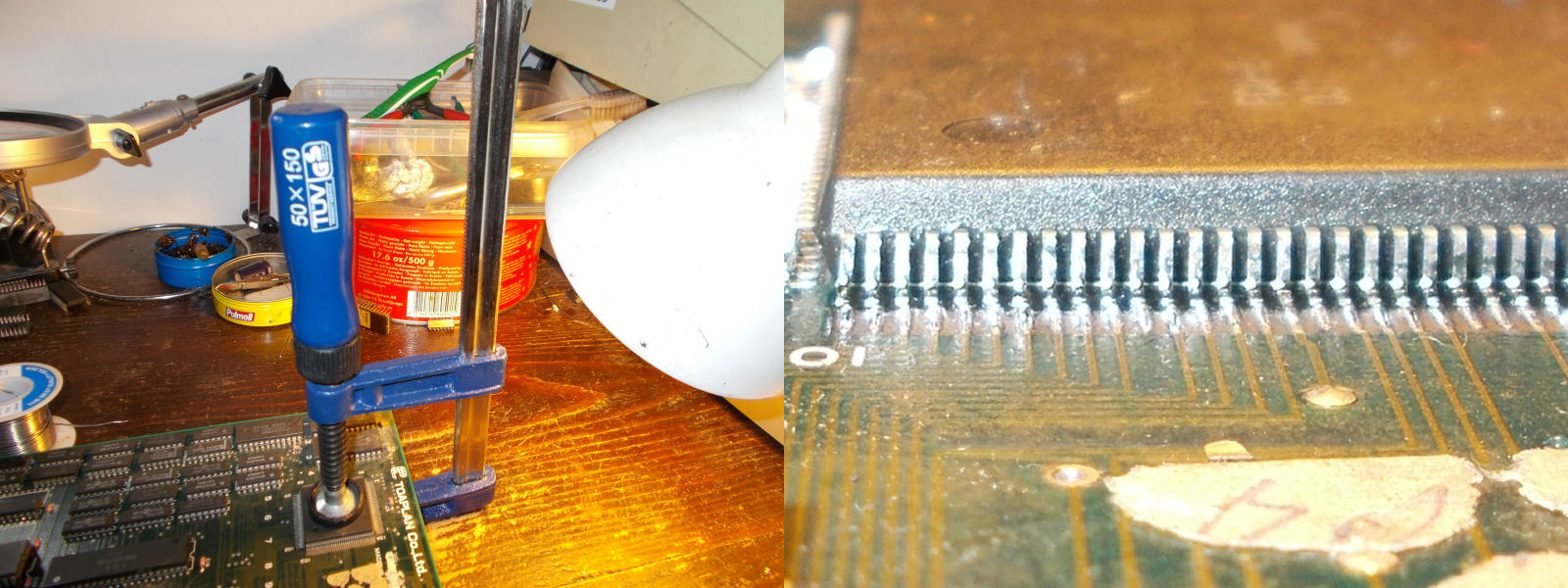
I started to troubleshoot first the input issue.As usual I inspected visuallly the board and found some corrosion near the JAMMA edge, some of the traces from the involved input pins to custom resistor/capacitor arrays and 74LS245 were eaten:
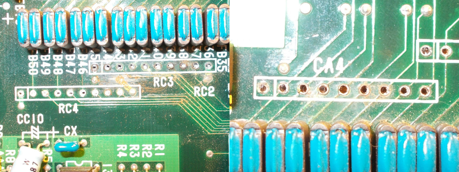
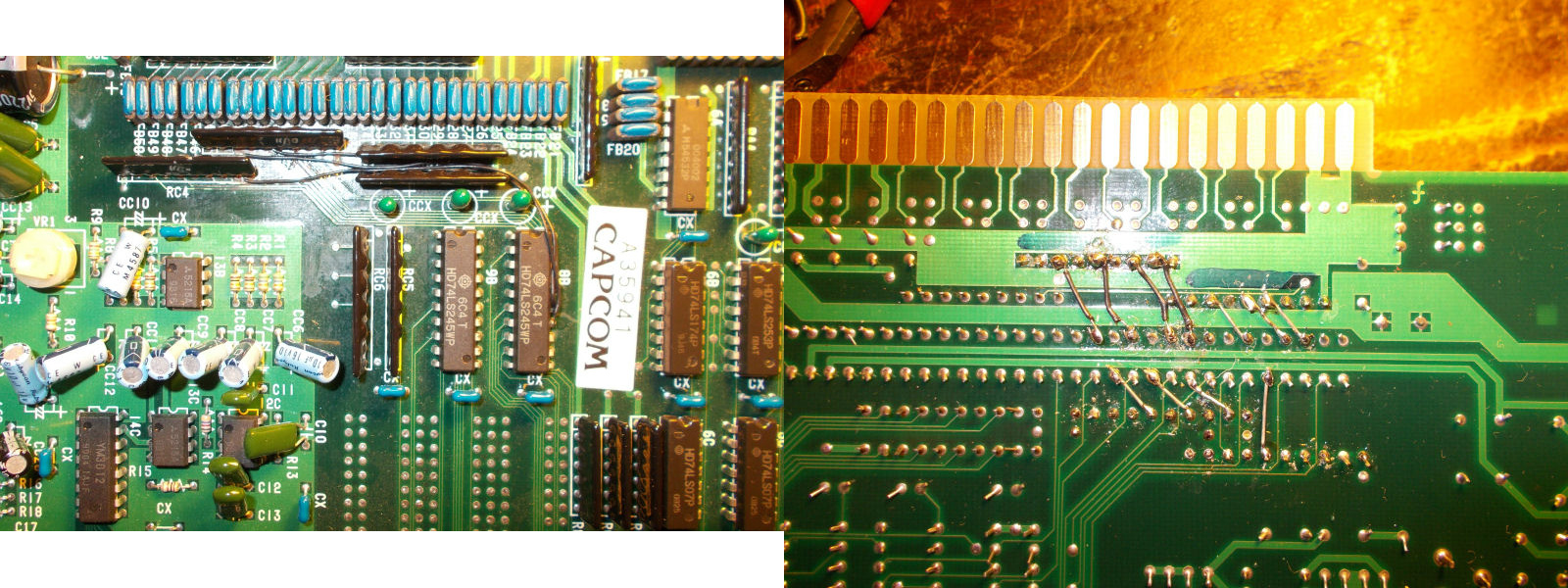
This was confimed also using my multimeter in continuity test.With some patching work and jumper wires I restored the connections and after this all controls were correctly working:
As for the red color issue, schematics for this hardware are available so I went to look at the involved circuit:
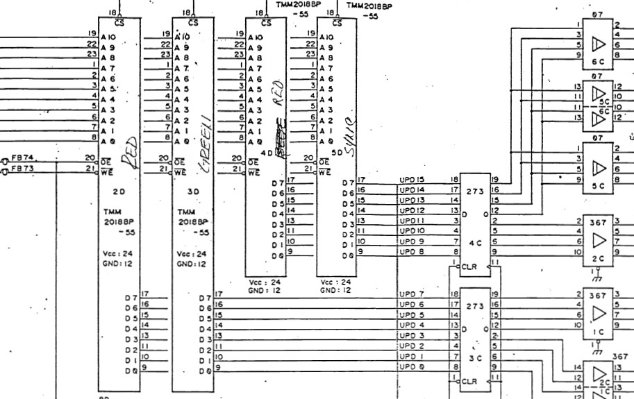
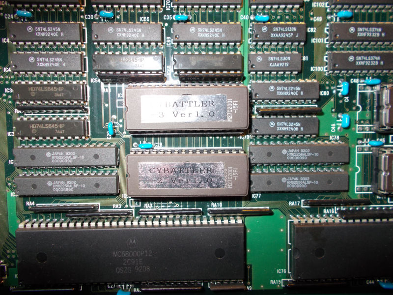
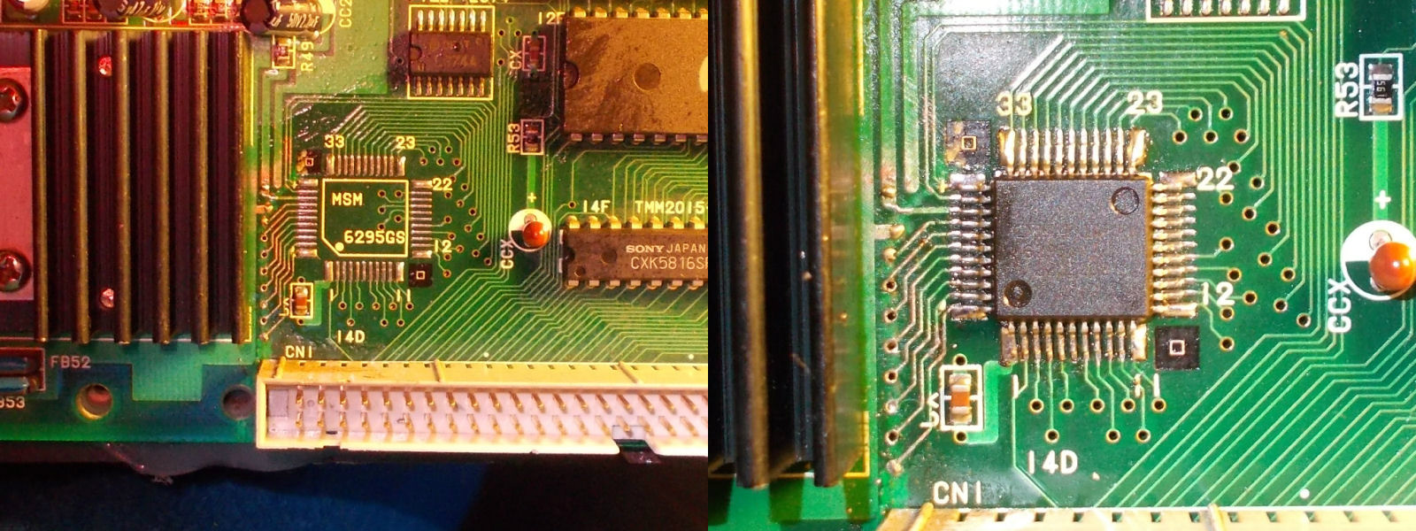
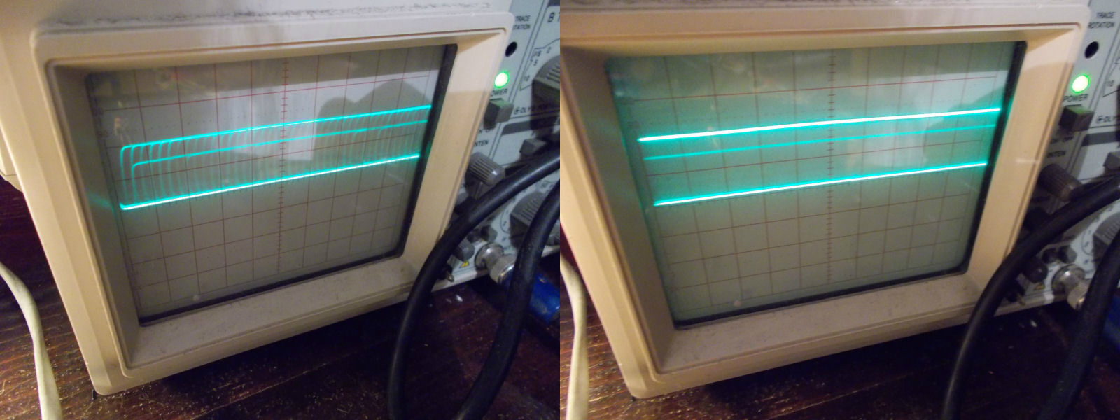
I found weak data signals on the two CXK5814 SRAMs (compatible with the TMM2018 suggested by schematics and PCB silkscreening) @4D and 5D (good on left, bad on right) :
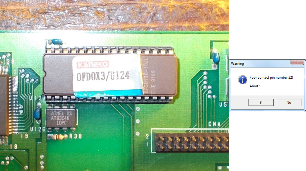
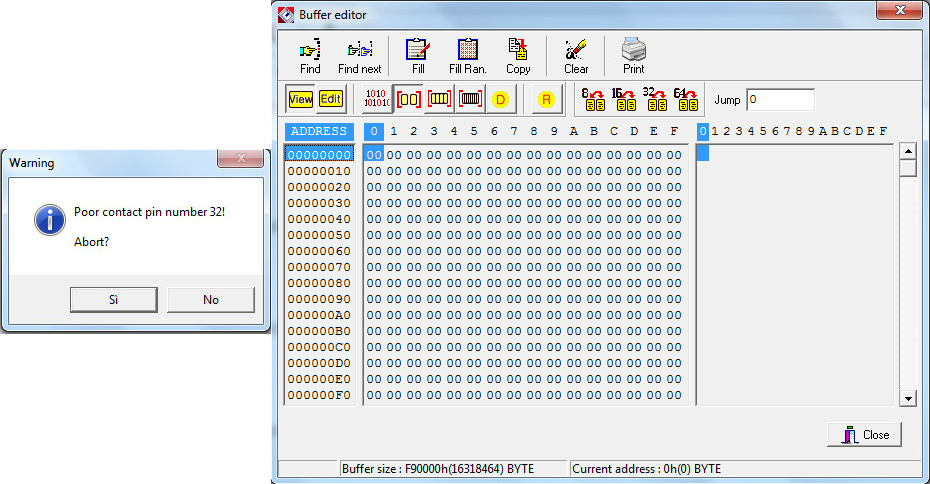
Since the data bus is shared between these two chips I could not know which was exactly the bad chip affecting the other so I piggybacked both them and when I did it on the one @5D, the red color was restored.So I desoldered the chip and it failed the test in my programmer:
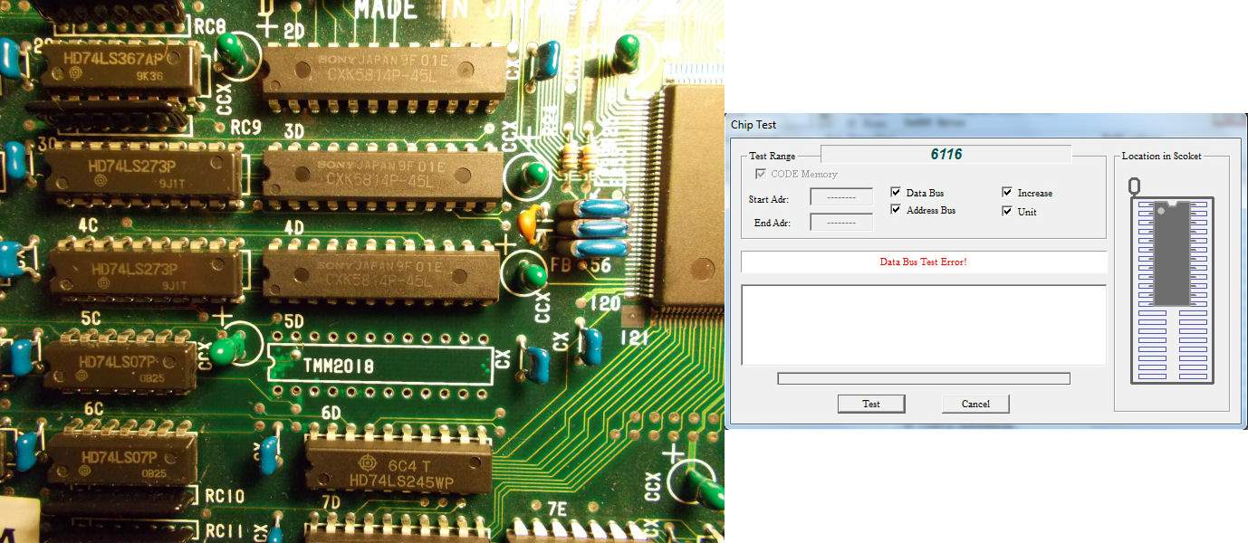
Fitted a new SRAM chip fixed the board completely.