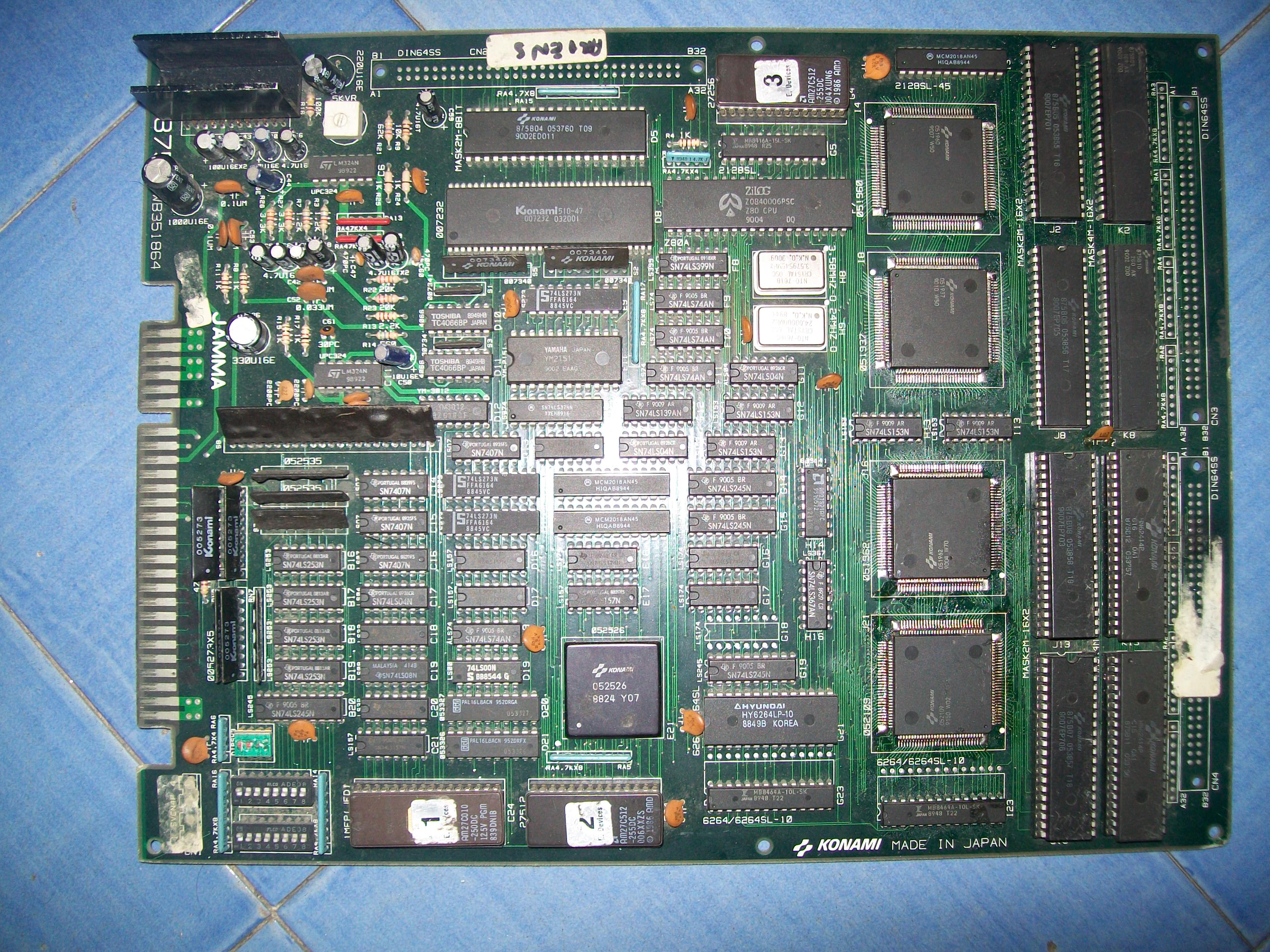
Received this faulty Konami Aliens PCB for repair :
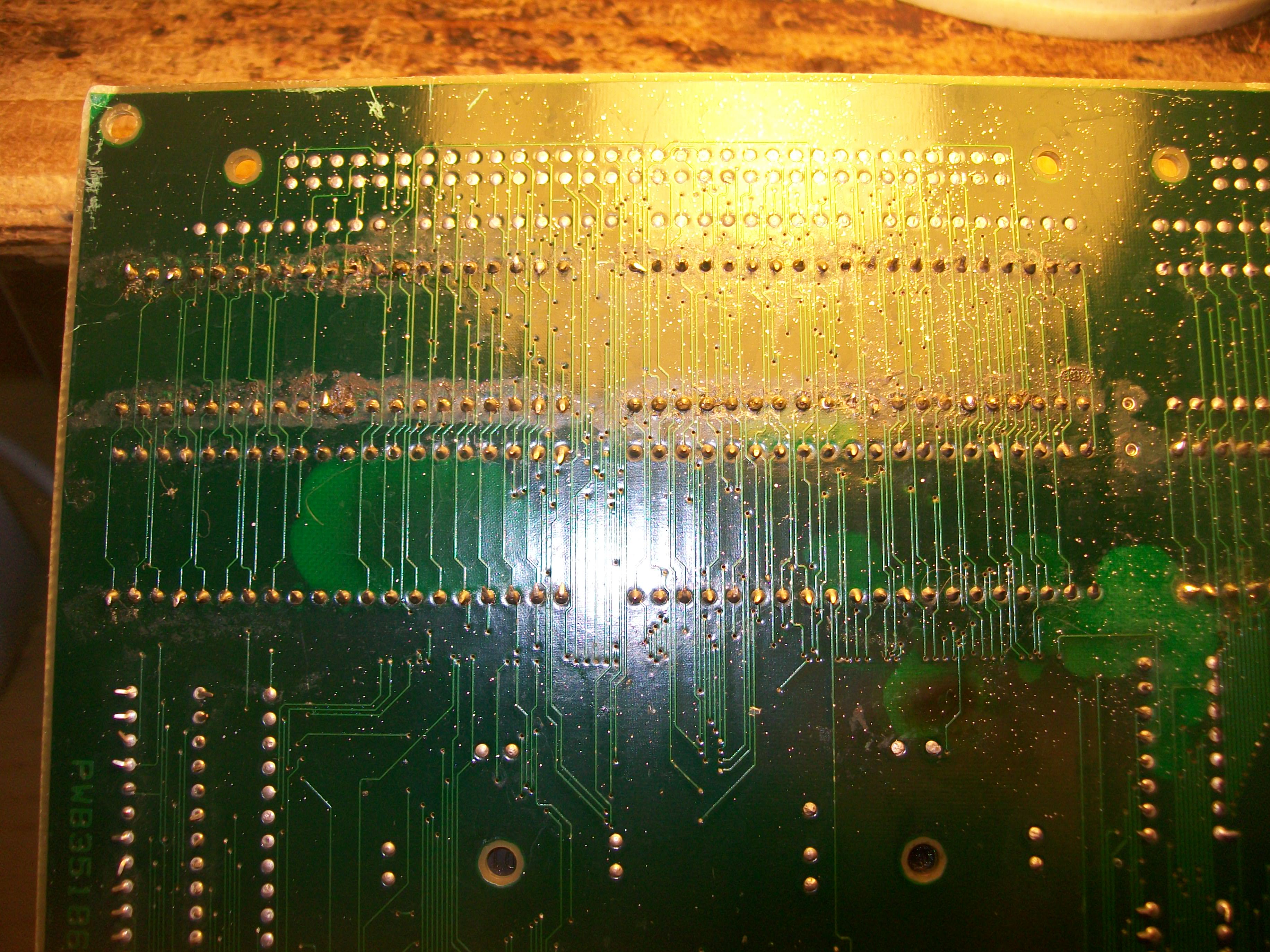
Board was in poor condition, dirty, custom ASICs were full of flux residual, four GFX 4Mbit MASK ROMs were removed and socketed most likey using improperly an heat gun judging from bubbles on solderside of the PCB:
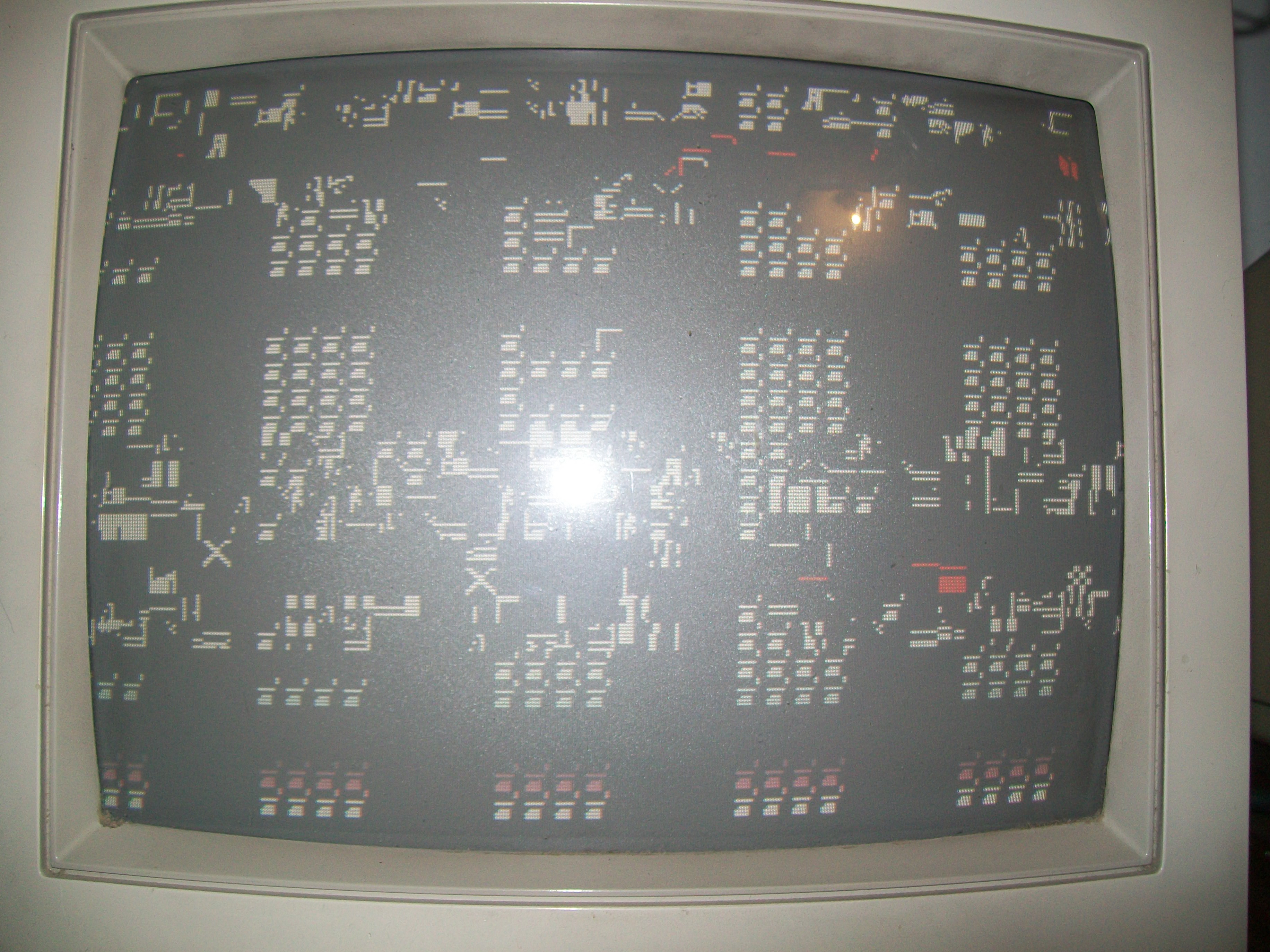
For first I washed the board.Once dried, I powered it up and I was greeted by this repeating screen :
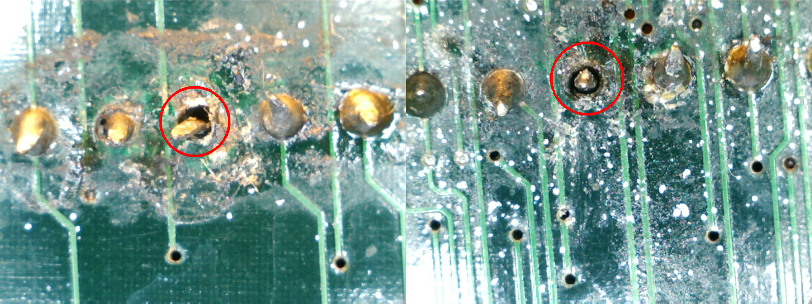
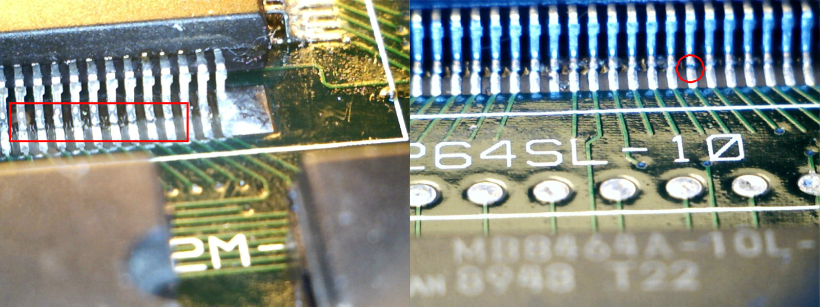
This should be the self-test report but graphics was all messed up sign that there was some problem in the tiles generation (the red characthers most likey referred to some RAMs reported as bad).Therefore I went to inspected the reworked area on solderside and found that a couple of rivets were ripped off during the desoldering operation, these should have tied to VCC since they were pin 31 (/BYTE) of two 4Mbit MASK ROMs
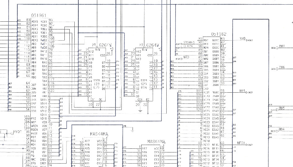
I checked all the connections on the reworked area against schematics :
I found some poor contact between the two tile generators ‘052109’ – ‘051962’ and MASK ROMs/ RAMs
This allowed the board to succesfully boot but some tiles had bad colors:
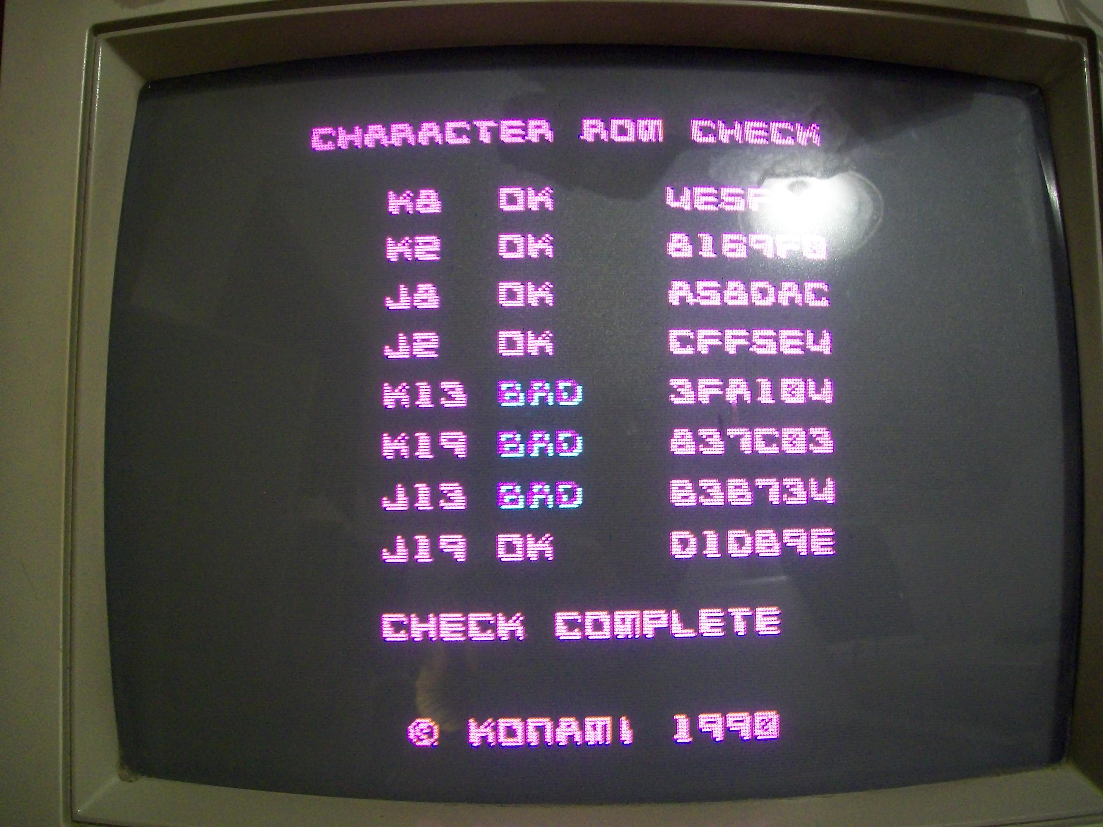
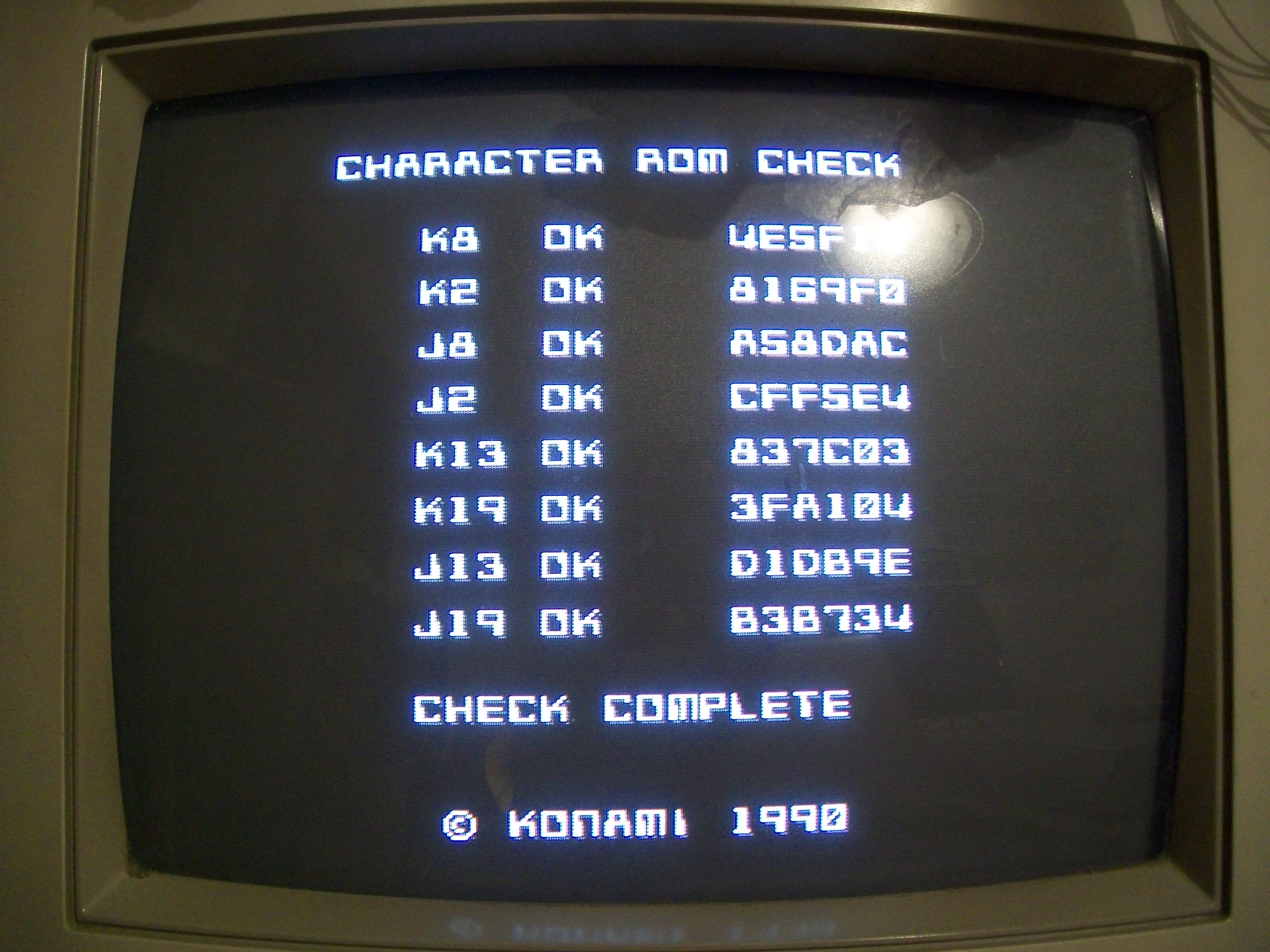
MASK ROMs test reported three bad devices:
Since they were socketed I dumped them and compared against MAME.They resulted good but I realized they were put in wrong sockets!I swapped them and MASK ROM test succesfully passed :
No other issue was found so also this board was declared as 100% working.
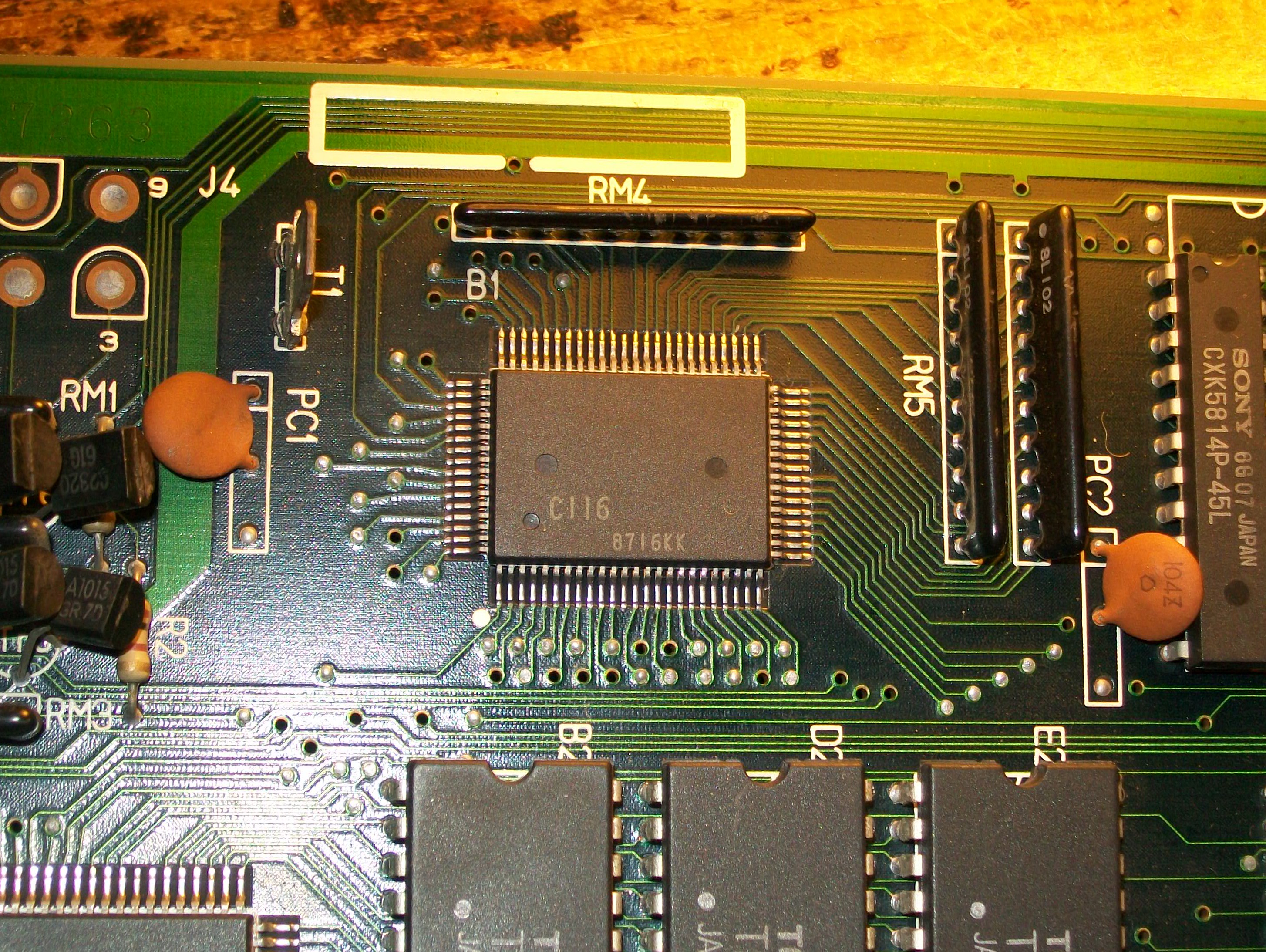
Got this Namco System 1 CPU board from my friend (and member here) Corrado:
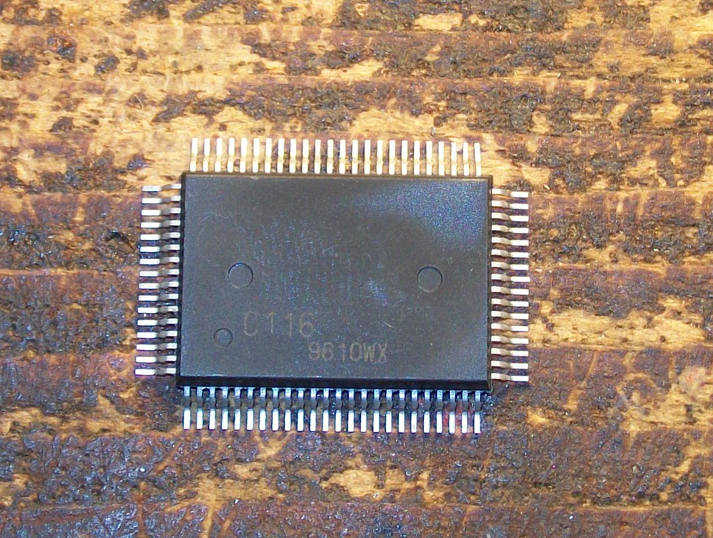
He told me the board developed a color issue, the GREEN was missing at all.He troubleshooted it and was sure that it was due a faulty custom ‘C116’ which generates the RGB video output:
but he had no spare of it so decided to send me the board.Once received I could see myself the issue trying the board with a Galaga88 ROM board:
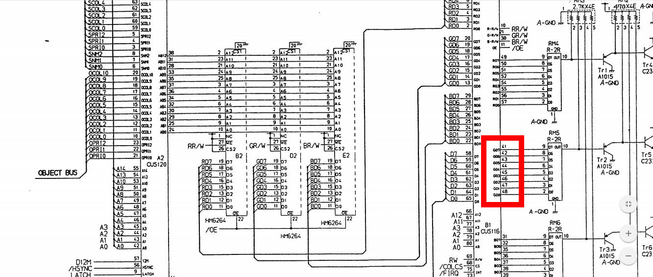
Besides the missing GREEN color, the board behaved strangely.You could not coin-up with both players but only with the SERVICE button but, once started a game, a “TEST PROGRAM INITIALIZE ERROR” message was displayed.I probed the outputs of this custom ‘C116’ and all the ones related to the GREEN color were stuck low:
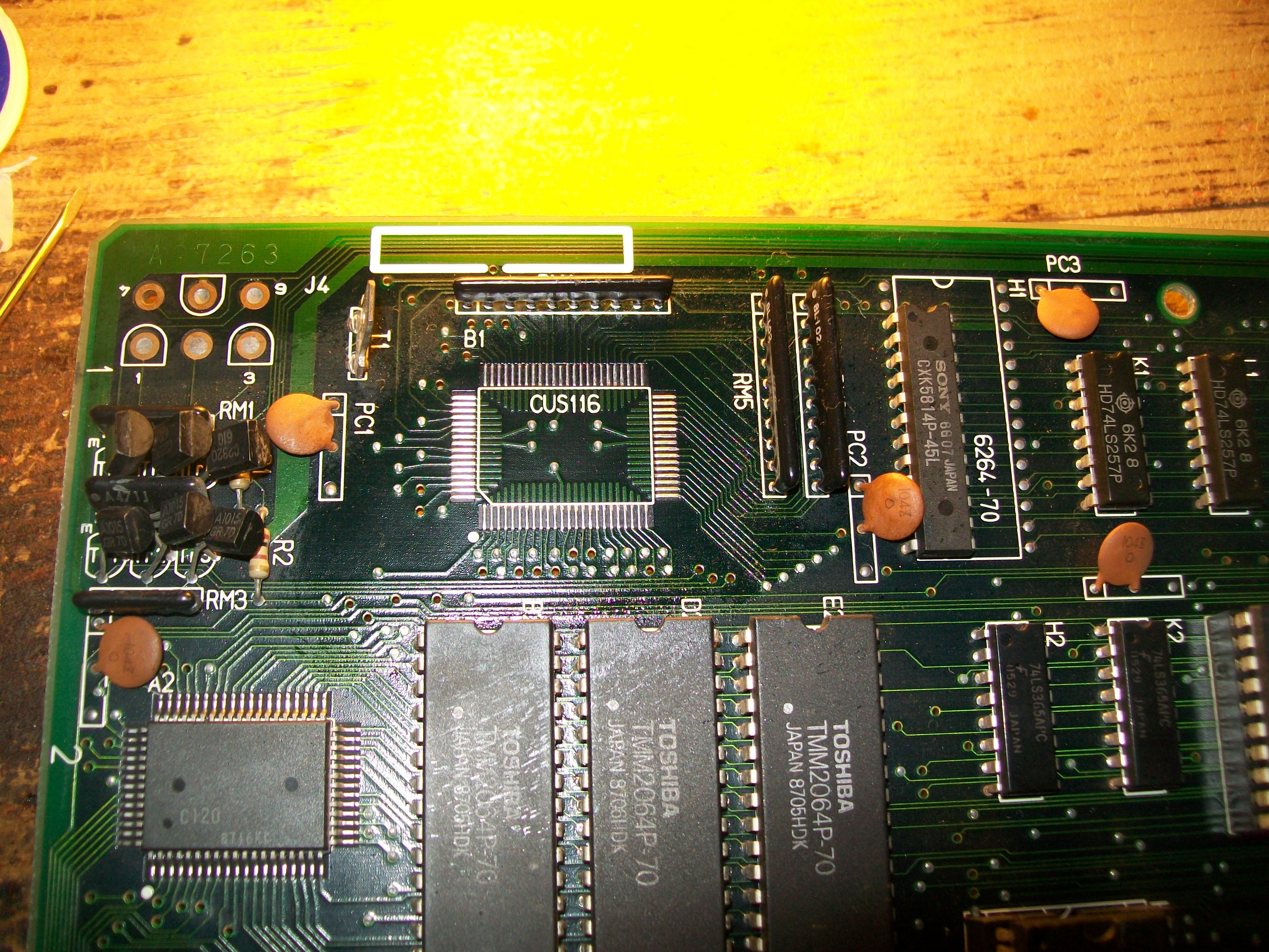
I removed the faulty one:
The spare was taken from a Point Blank donor board (this custom is present also on Namco System 2 hardware)
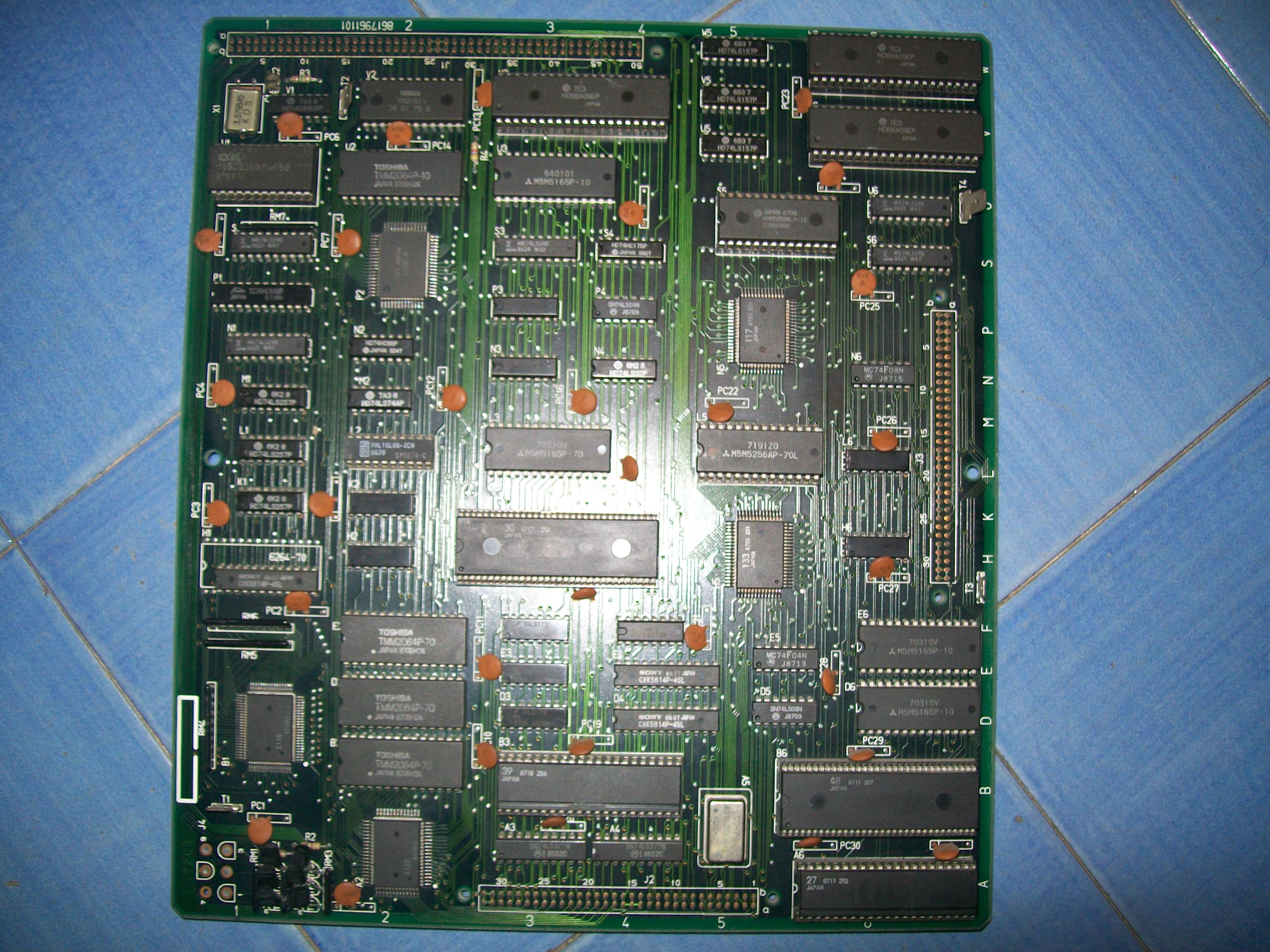
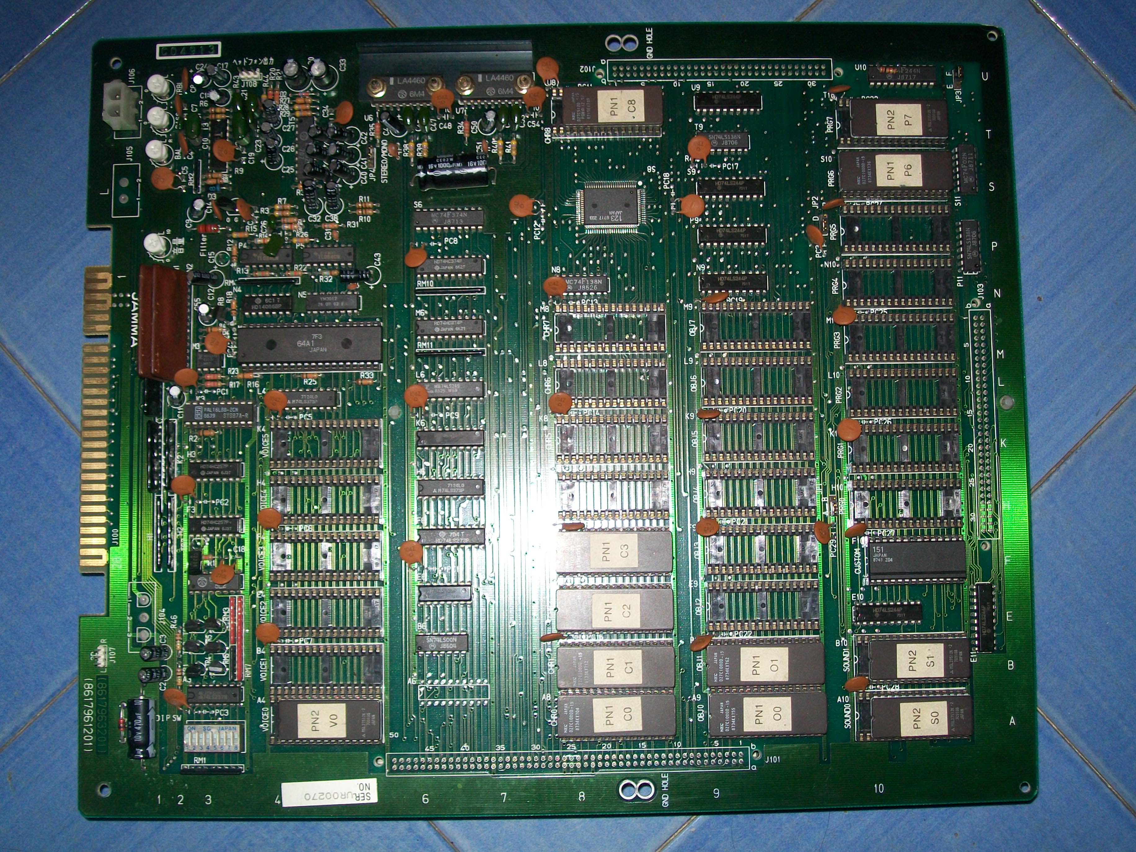
Had this faulty Pac-Mania boardset in a trade some years ago :
As many of you know, this game runs on Namco System 1 hardware (made of a CPU and ROM board) which features some classic titles like Splatterhouse, Galaga88 and others.Here are the tech specs :
Processors:
Main CPU: Motorola M6809 @ 2.048 MHz
Sub CPU: Motorola M6809 @ 2.048 MHz
Sound CPU: Motorola M6809 @ 1.536 MHz
MCU: Hitachi HD63701 @ 1.536 MHz
Sound:
Yamaha YM2151 FM sound chip @ 3.57958 MHz
Custom 8-channel wavetable stereo PSG @ 96 kHz
2-channel DAC
My board had two noticeable faults : the sprites had wrong colors in certain positions and music was missing, only some FXs were present :
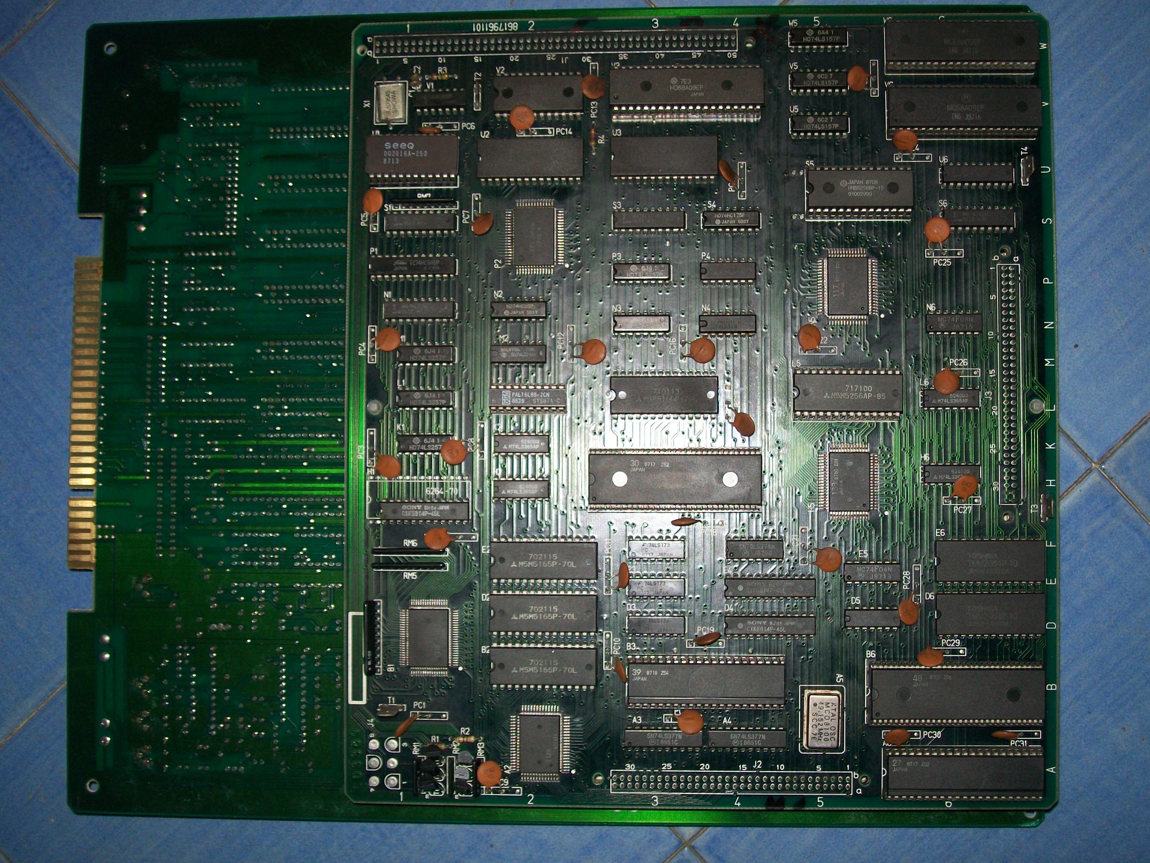
For first I swapped the boards with a good set and could narrow the fault in the CPU one (the smaller one) :
As you can see , hardware uses many custom ICs each of which with different functions, here are the ones used on CPU board (taken from MAME source)
CUS27 clock divider
CUS30 sound control
CUS39 sprite generator
CUS48 sprite address generator
CUS95(x5) I/O interface
CUS99(x2) sound volume
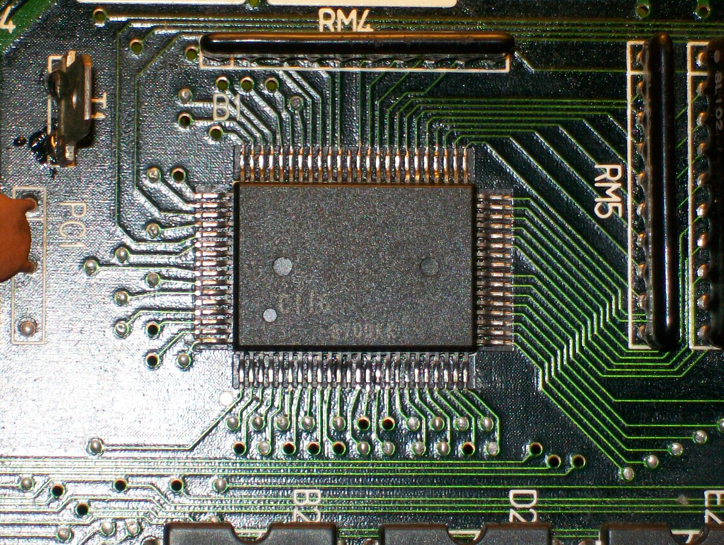
CUS116 display output generator
CUS117 main/sub CPU MMU
CUS120 sprite/tilemap mixer and palette address interface
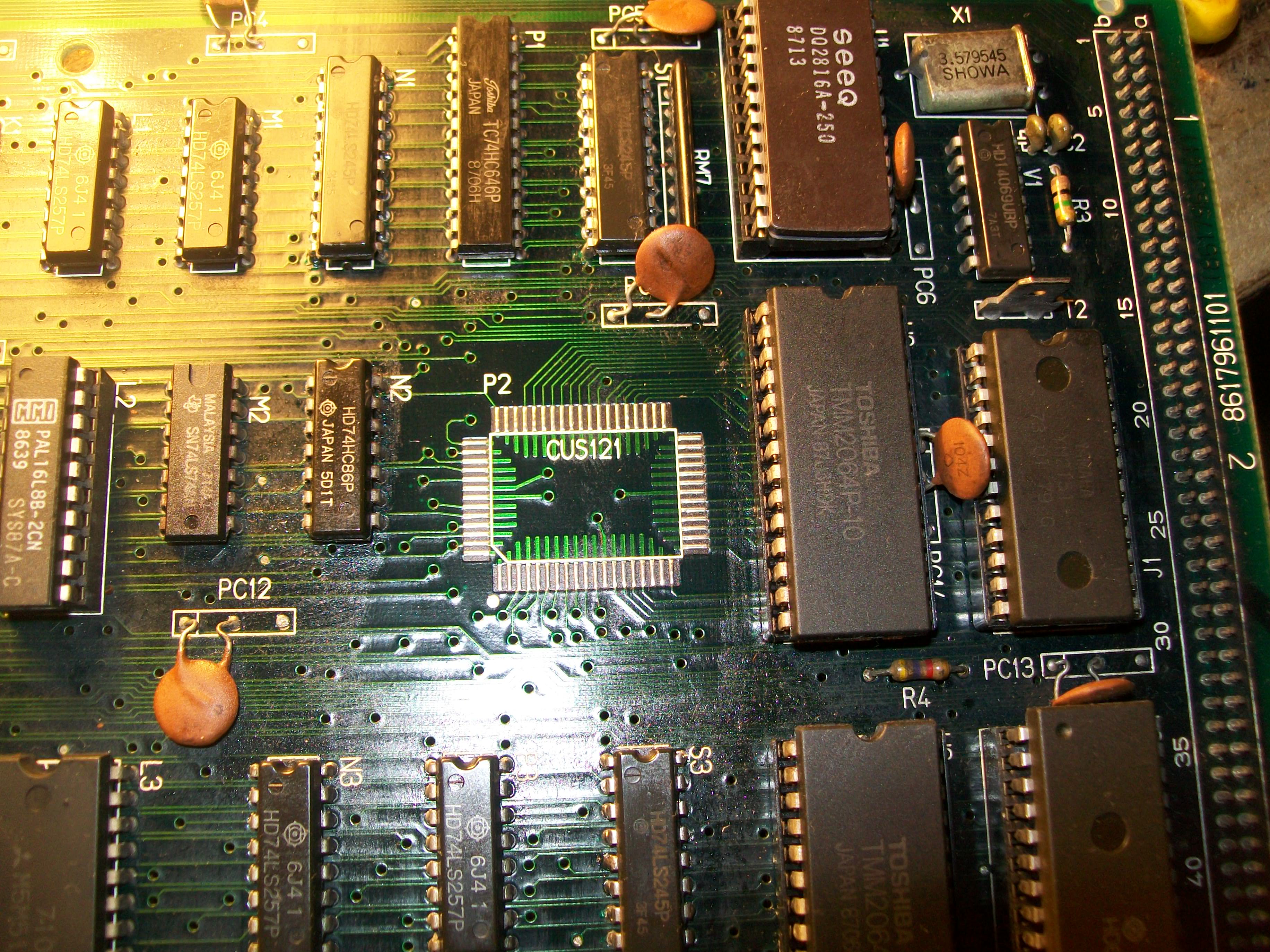
CUS121 sound CPU address decoder
CUS123 scrolling tilemap address generator
CUS133 tilemap generator
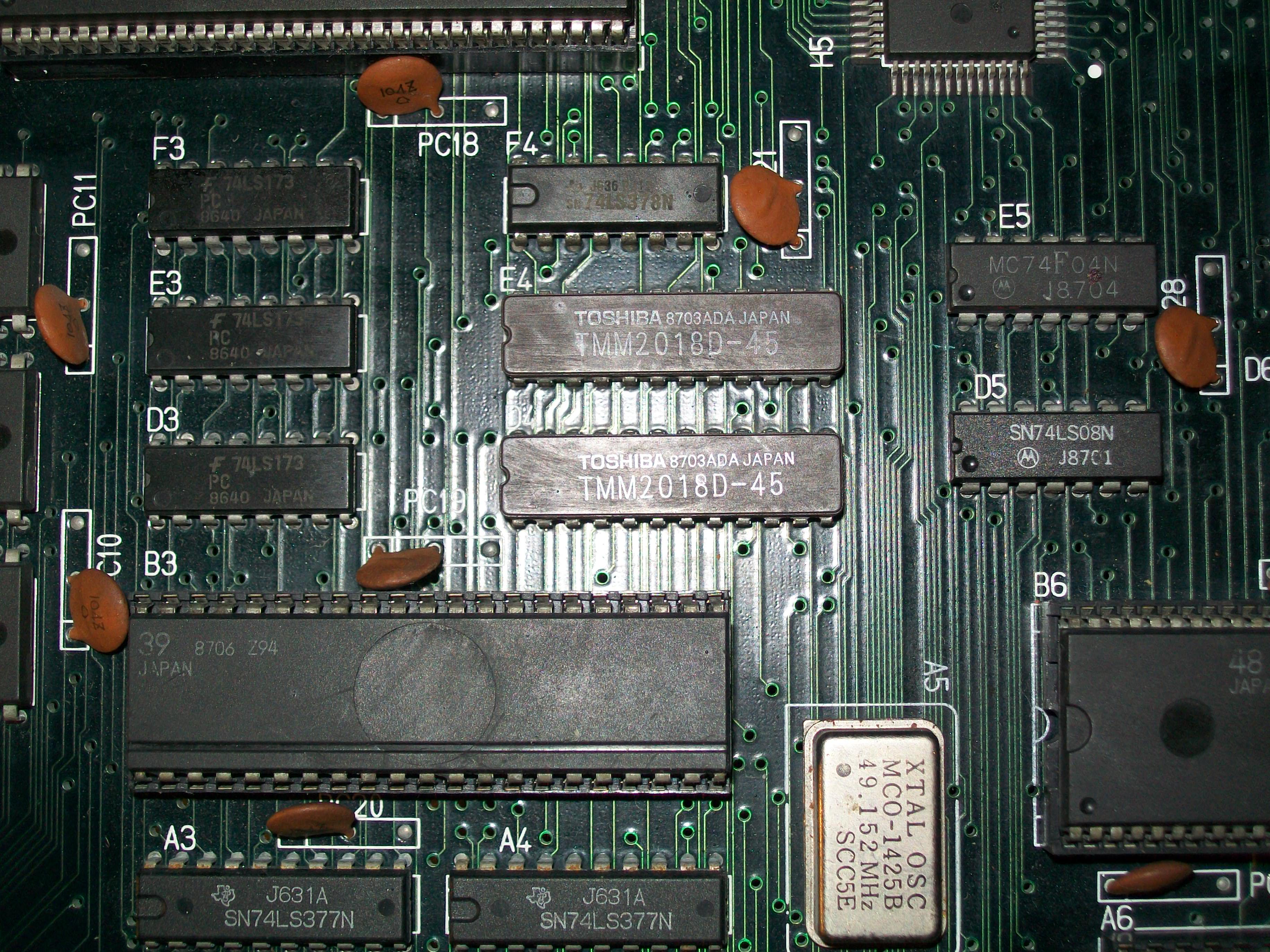
The sprites are generated by the custom ’39’ which I test as good in another board (as well as all the other customs).This IC addresses two 8K x 8-bit static RAMs @D4 and E4:
Checking this ares against schematics I found a broken trace between pin 1 (address line A7) of both RAMs:
Patching the trace restored the sprites so I went to troubleshoot the sound issue.As said music was missing and game behaved strangely since I was not able to really enter in game, the selection screen was repeating in an endless loop:
The music is generated by the YM2151 sound synthesis IC but probing its bus revealed no data coming to/from I/O lines:
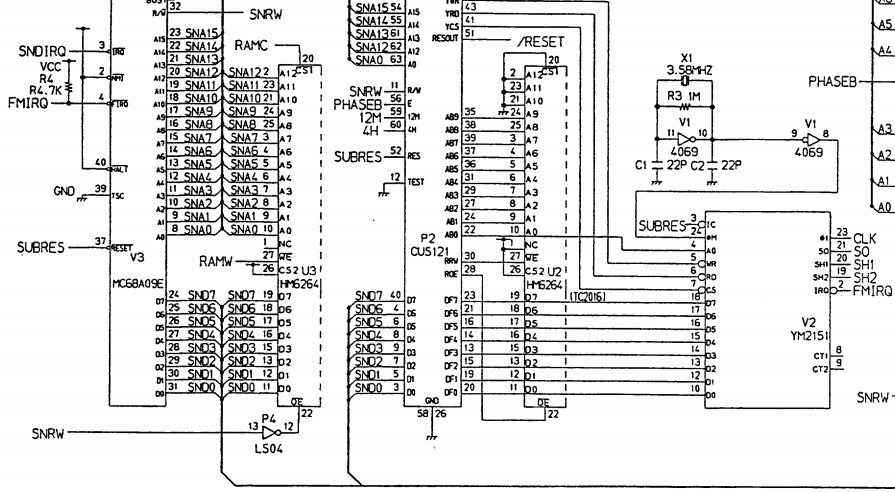
The custom ‘121’ sits between the data bus of the 6809 audio CPU and YM2151:
I replaced it :
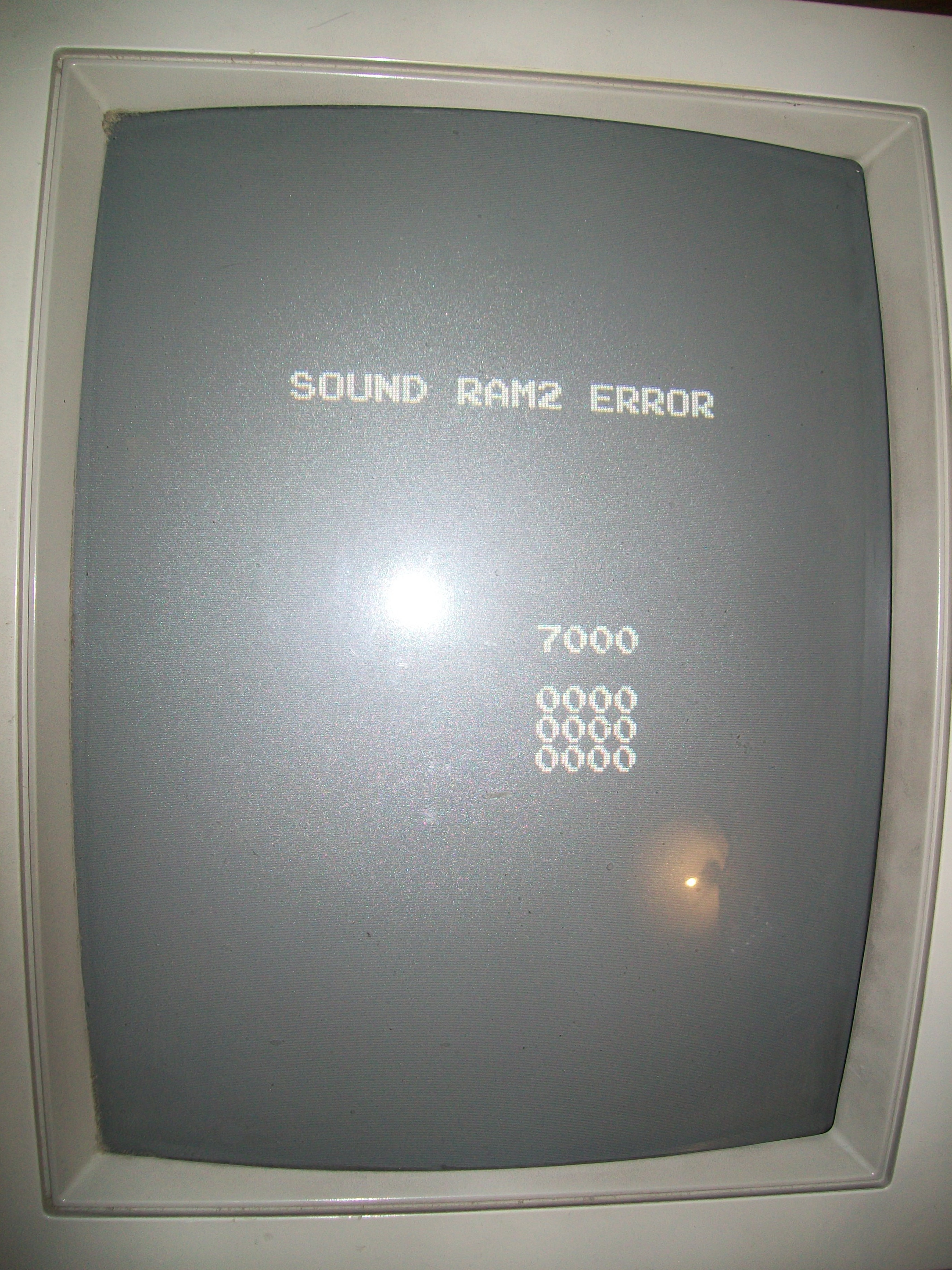
but this didn’t fix the issue, music was still missing.The TEST mode gave me a “SOUND RAM2 ERROR” which is not covered in the service manual:
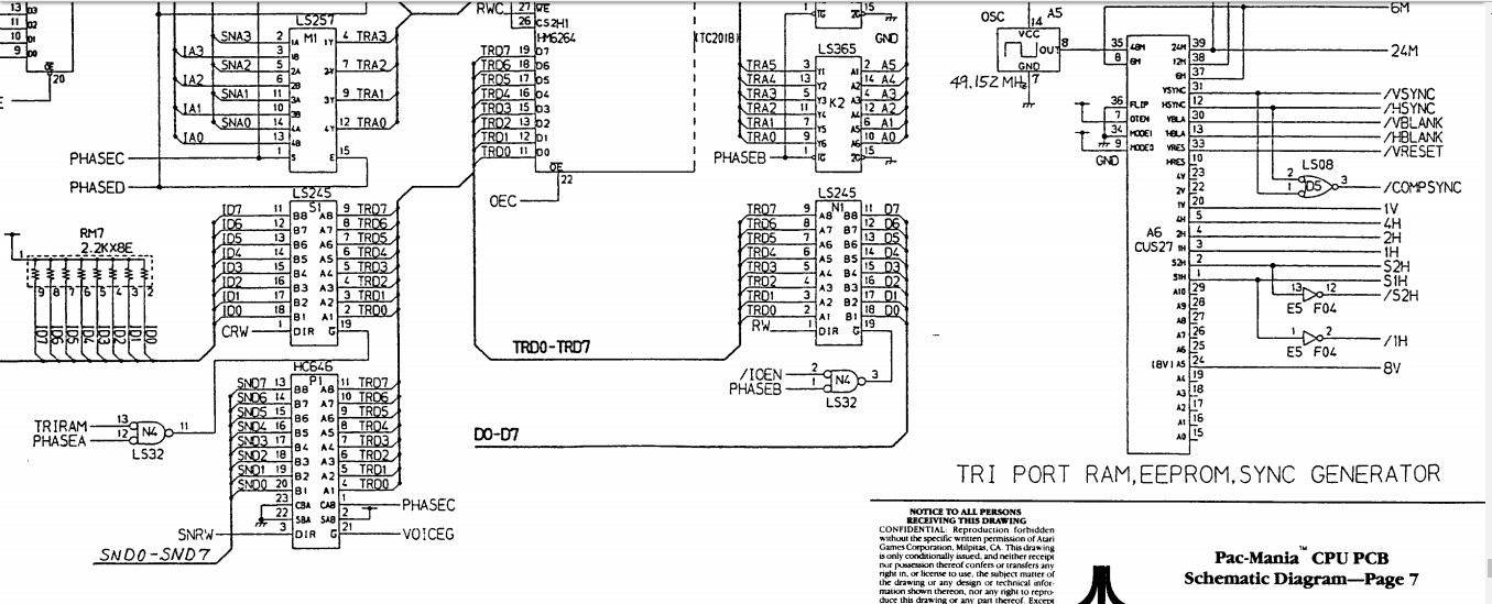
Looking at MAME sound memory map :
staticADDRESS_MAP_START(sound_map,AS_PROGRAM,8,namcos1_state)AM_RANGE(0x0000,0x3fff)AM_ROMBANK("soundbank")/* Banked ROMs */AM_RANGE(0x4000,0x4001)AM_DEVREAD("ymsnd",ym2151_device,status_r)AM_RANGE(0x4000,0x4001)AM_DEVREADWRITE("ymsnd",ym2151_device,read,write)AM_RANGE(0x5000,0x53ff)AM_DEVREADWRITE("namco",namco_cus30_device,namcos1_cus30_r,namcos1_cus30_w)AM_MIRROR(0x400)/* PSG ( Shared ) */AM_RANGE(0x7000,0x77ff)AM_RAMAM_SHARE("triram")AM_RANGE(0x8000,0x9fff)AM_RAM/* Sound RAM 3 */AM_RANGE(0xc000,0xc001)AM_WRITE(sound_bankswitch_w)/* ROM bank selector */AM_RANGE(0xd001,0xd001)AM_DEVWRITE("c117",namco_c117_device,sound_watchdog_w)AM_RANGE(0xe000,0xe000)AM_WRITE(irq_ack_w)AM_RANGE(0xc000,0xffff)AM_ROMAM_REGION("audiocpu",0)ADDRESS_MAP_END
this error is related to the part of circuit called ‘TRI PORT RAM’ in schematics :
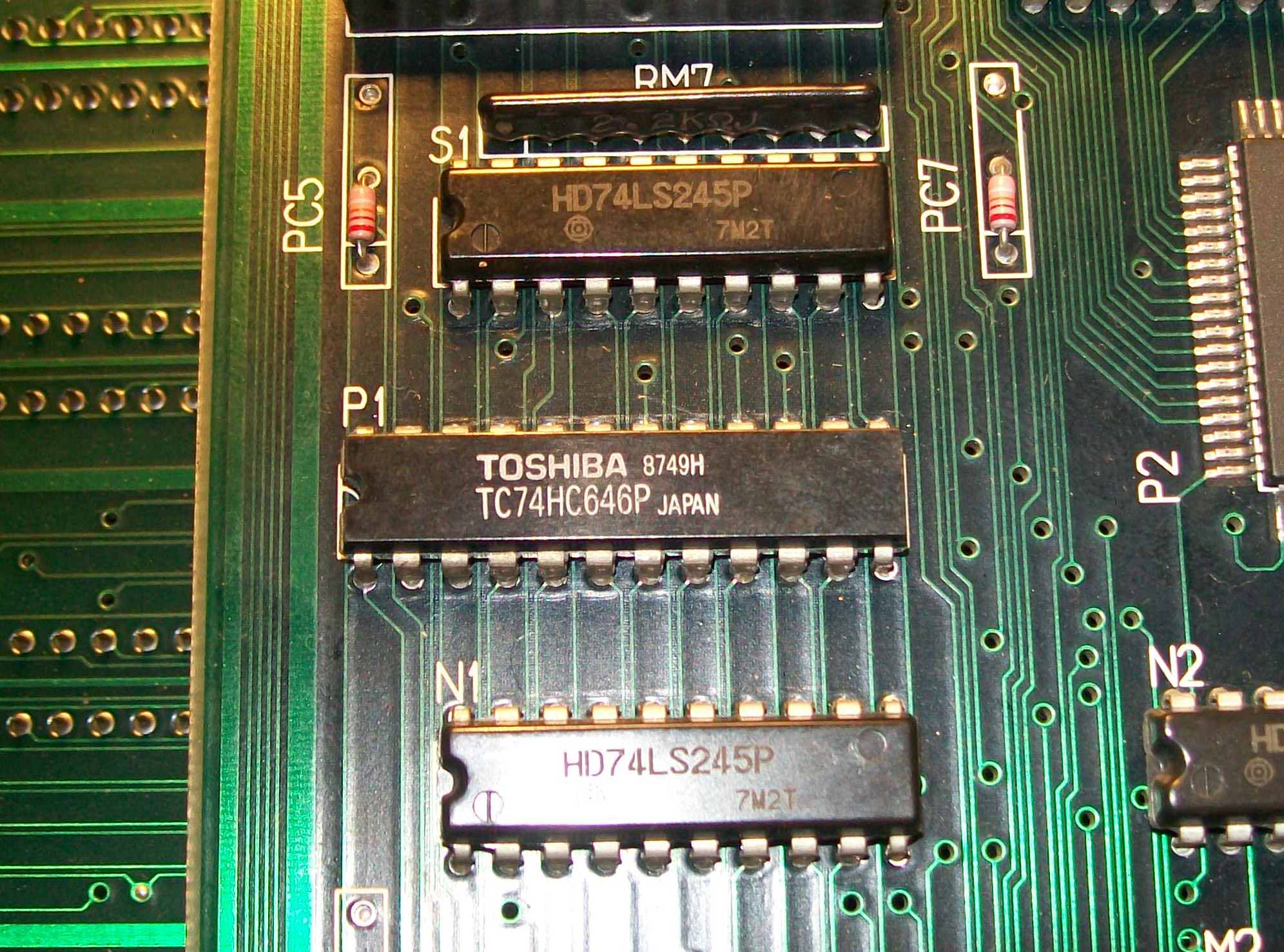
I checked connections, probing the ICs in-circuit with a logic comparator, all was fine.The ony IC I had doubts about was a 74HC646 @P1 :
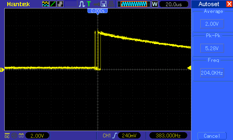
Its signal transitions didn’t seem regular to me :
I decided to remove it anyway and test it out-of-circuit.It failed:
Since it’s an unusual IC (it’s a CMOS device, sensitive to ESD, this could explain the fault) , I took the spare from another faulty Namco System 1 CPU board.This restored the music so I could declare the board as 100% working.
PCB Repair LogsComments Off on The New Zealand Story repair log #2
Dec302016
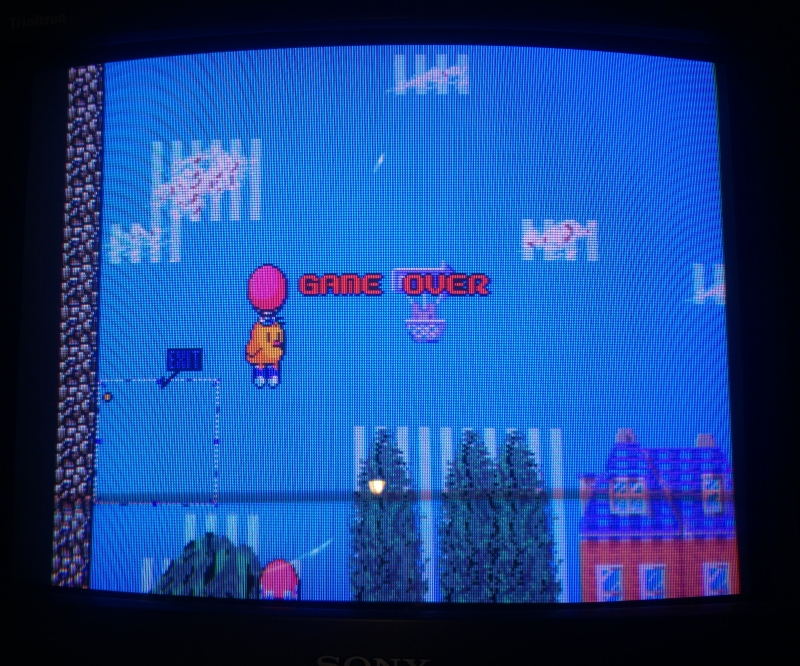
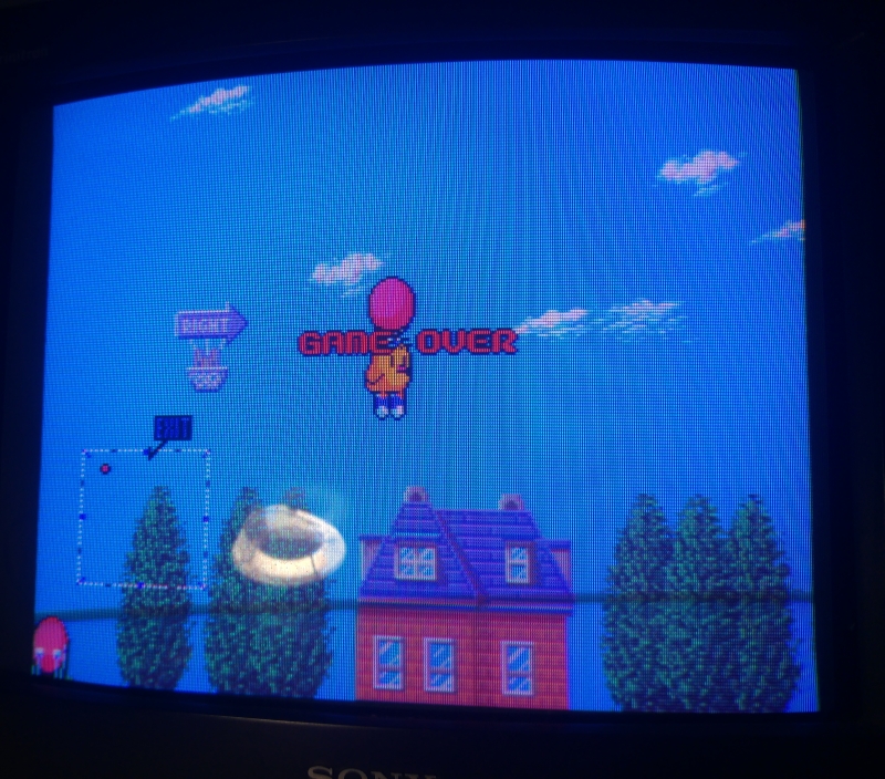
While waiting for the PCB’s to come for my resistor ladder replacement this New Zealand Story PCB decided to fail again.
I suspected more failed MASKROM’s but they are dumped out fine and that was the start of my frustrations.
I was a bit lost so I made up some partial schematics but found nothing.
Jailbars are usually a sign of a ROM failure but as the original MASKROM’s are 23C1000 and there is no easy drop in replacement available I relied too much on checking the ROM’s out of circuit as I didn’t want to needlessly make up ones with the adapters I ordered last time.
Turning to MAME for help, I made a program that takes a ROM dump and allows me to introduce a ‘bad bit’ to test in MAME. By doing this I closed in on what could be a potential candidate for a ROM issue.
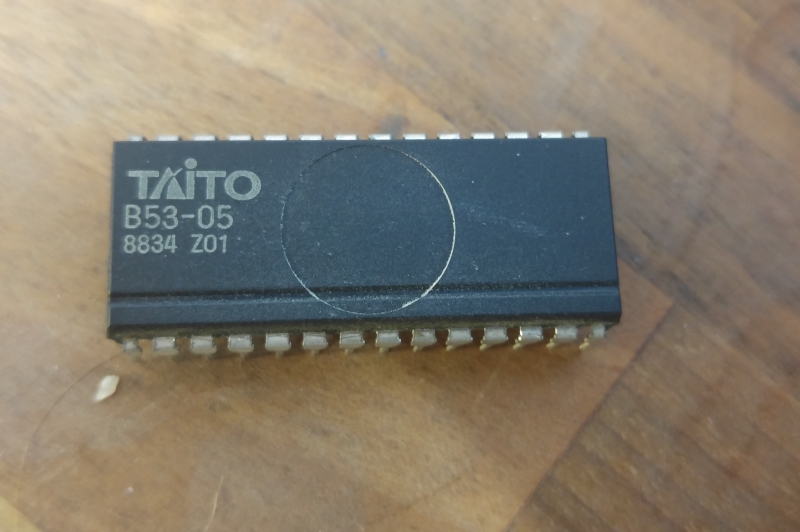
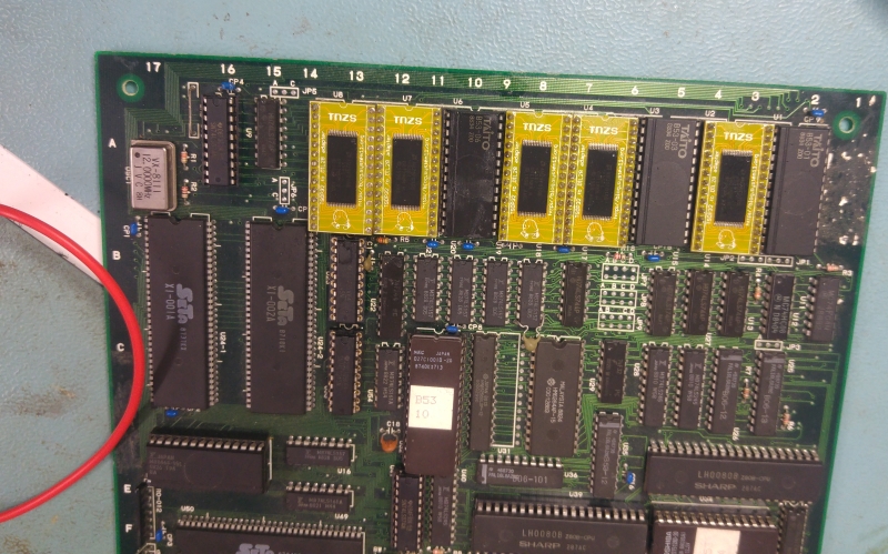
B53-05 gave me similar issues when introducing bad bits and making up another MASKROM replacement proved this as the problem was fixed!
This kind of problem is becoming quite common now I feel. The ‘perfect’ conditions generated by a programmer gives no issues reading the ROM but for some reason they don’t work well in circuit.
As you may recall from my last repair log on this PCB, I found a resistor ladder that was broken. Anyway I made up a PCB that allowed me to fit SMT resistors to whatever values I wanted. I made up on and tested.
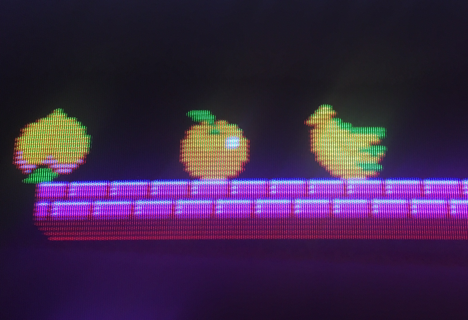
I purchased a “mostly working” original Taito Bubble Bobble PCB for a good price, with the hopes of repairing it and adding it to my collection. The seller mentioned simply that there was an issue with the sprites. Upon testing the PCB, the fault presented itself. When the sprites rendered “normal” direction, they were fine. When rendered “horizontally mirrored”, extra odd-colored pixels were being drawn with the sprite. You can see the pink pixels to the right of Bub and the baby blue pixels near the fruits. It was especially noticeable on certain enemy types, quite distracting from the gameplay.
I investigated the roms, the ram and most of the TTL logic IC’s, all of the usual suspects tested OK. The PCB is in really nice shape, so I knew the issue wasn’t physical damage. At this point I was pretty stumped, and decided to email my good friend Caius. After explaining the symptom, and what I had already tested, he suggested looking into the 74ls163 4-bit counters near the graphics roms. They are a bit tricky to test with a logic comparitor, so I opted to test them out of circuit. All 5x 74ls163’s passed the TTL test in my Xeltek, so unfortunately the fault was not there.
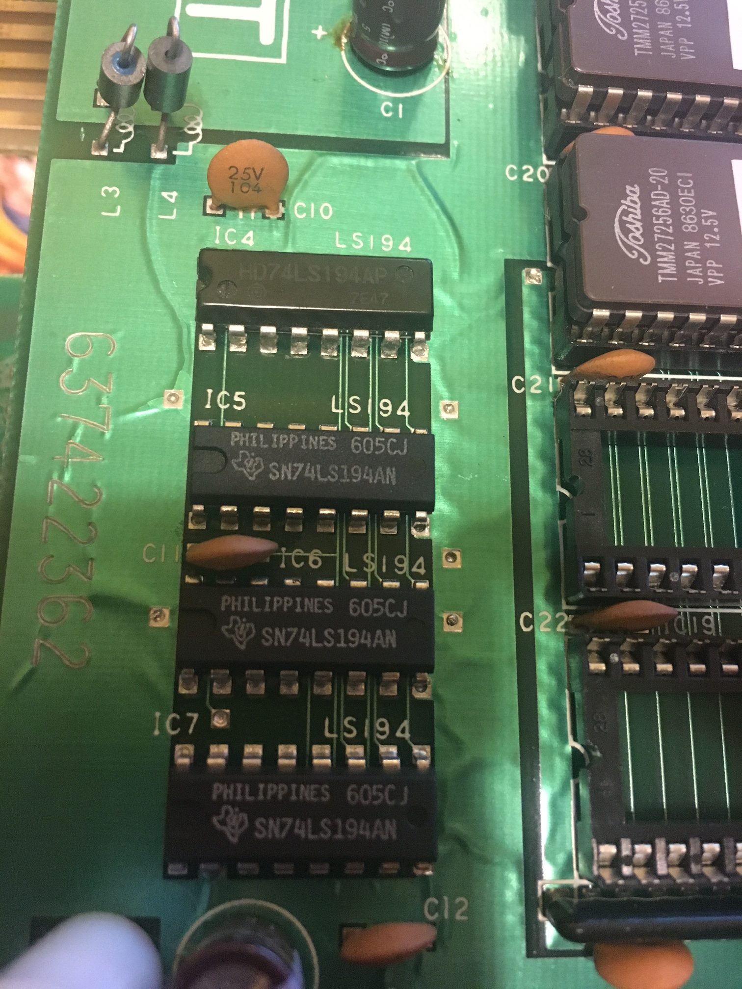
I decided to not give up hope however, and to look into the other TTL chips I was unable to test with my Logic Comparitor. I came across a bank of 4x 74LS194 shift registers. I tested them out of circuit (since my comparitor couldn’t analyze them), and finally I found the fault! One of the 4 registers was bad.
After digging through nearly my ENTIRE parts boards inventory, I finally found a donor IC on a dead Double Dragon board. It turns out not many arcade games used 74LS194’s in their design (likely they became integrated in custom graphics ASIC’s instead). I swapped the good shift register in, and the graphics problems are now fixed.
Big thanks to Caius for assisting me with this repair! He got me on the right track, and now this wonderful game can be enjoyed for years to come!