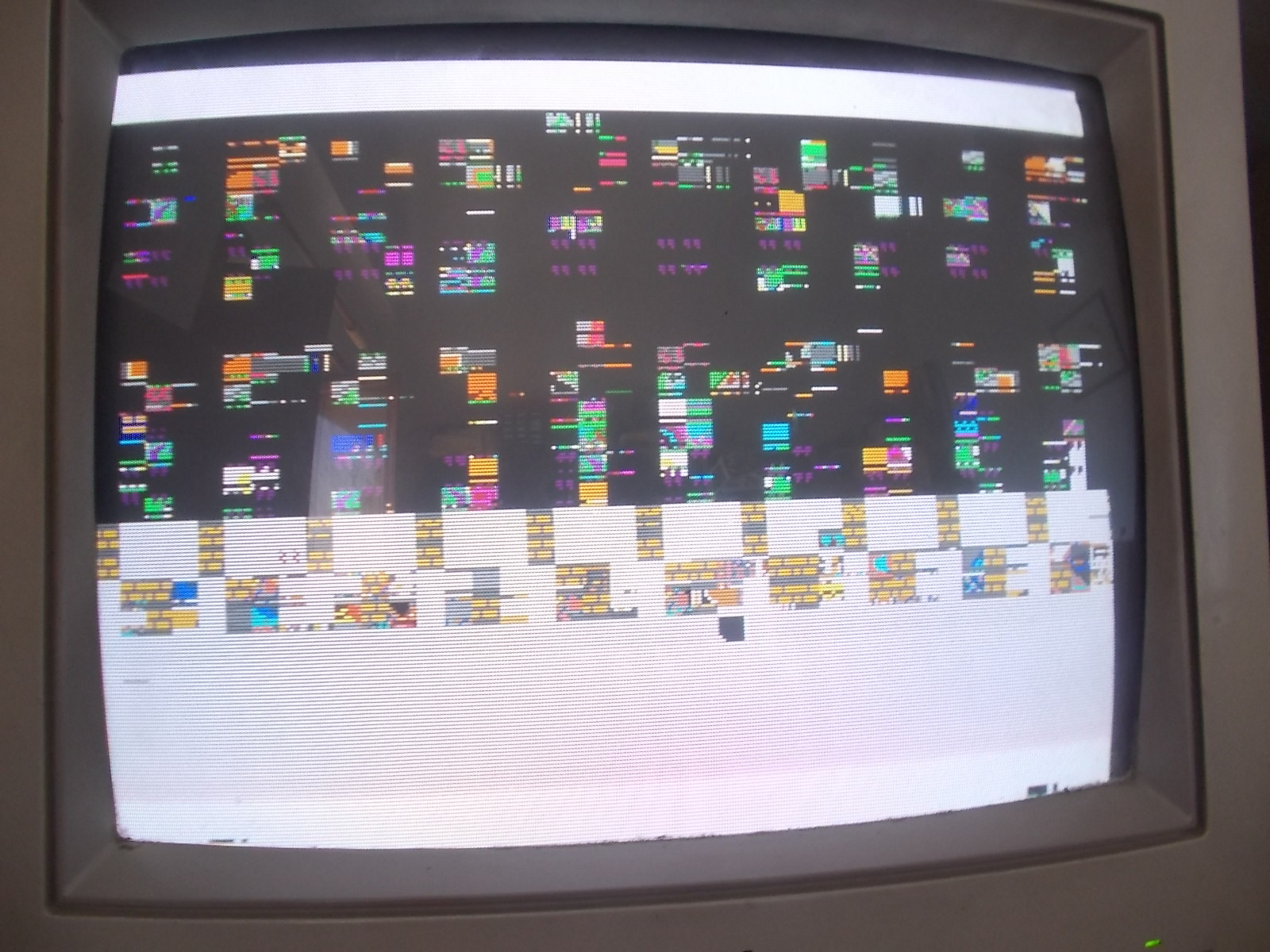
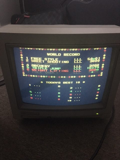
During my Hypersport’s repair I discovered a problem with the display of my Commodore 1084S monitor. Notice blue missing for “3 LONG HORSE” and “7 POLE VAULT”.
This will be the third time I’ve performed a repair on this old monitor which I’ve had since the early 90s for my Amiga 500 and 2000. At first I would suspect the AV7000 Supergun as the culprit. But subsequent tests would prove otherwise.
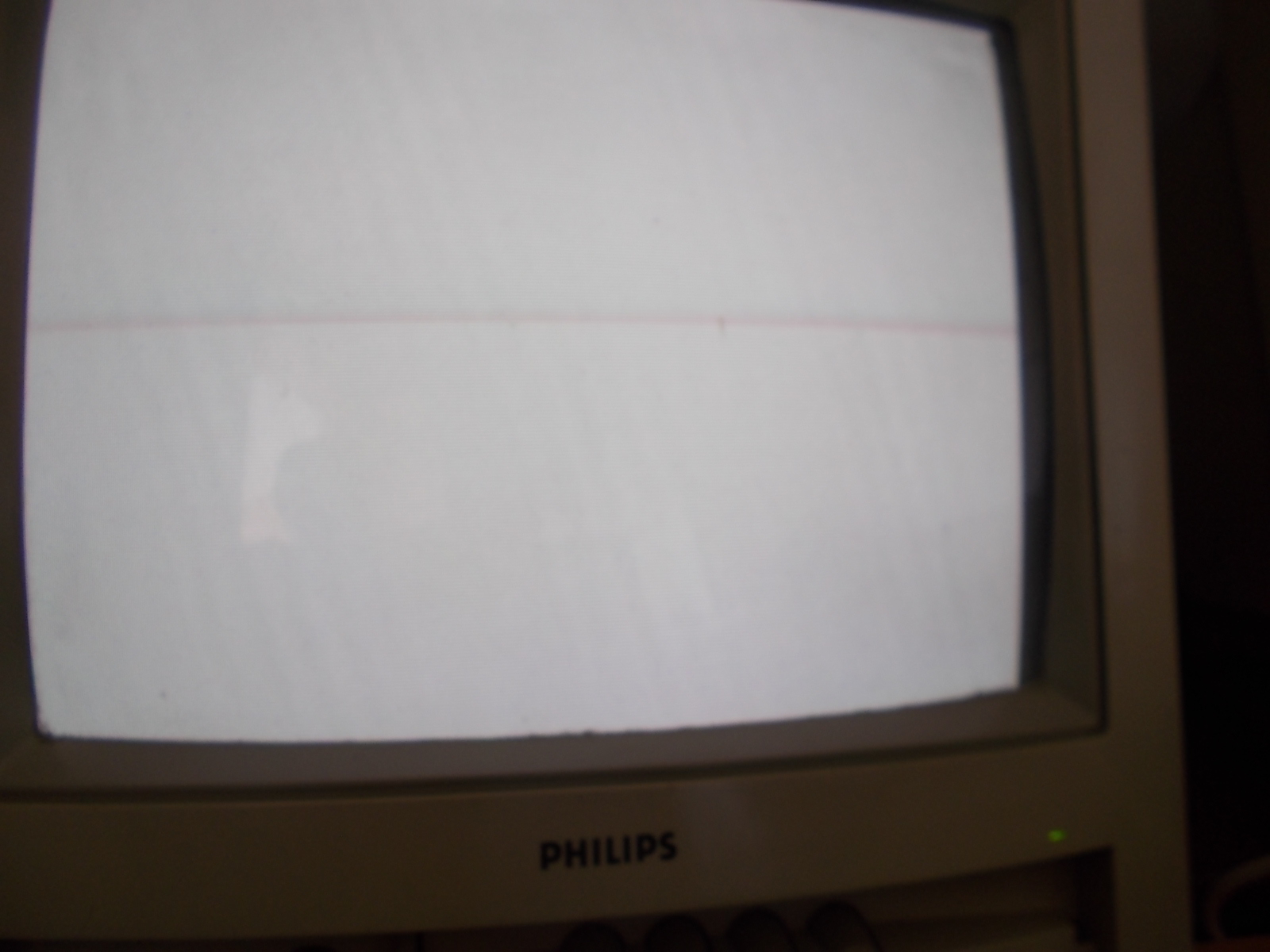
There’s definitely a better picture with composite or svideo from my c64 and Atari 8 bits but there seems to be a problem showing blue on the RGB input even though some blue is there ( turquoise , cyan.. etc ) in other images. Adjusting the blue gun and turning up the contrast just makes the backgrounds in Puzznic more blue. Where blue is supposed to be on the screen, it seems to not be present as though the signal were being cancelled out. With no RGB signal to the monitor at all, it defaults to a blue screen instead of a white one.
Apologies for the sync bands.
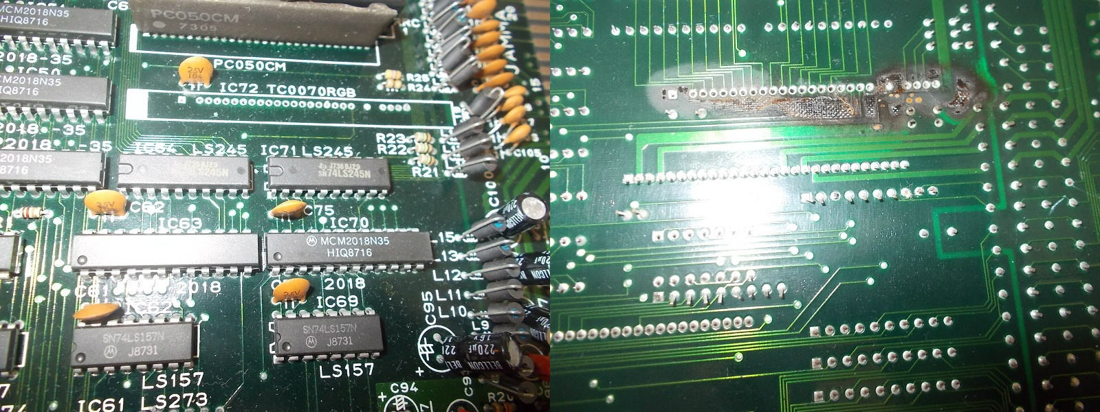
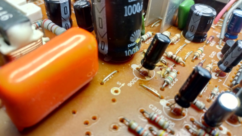
I suspected the neck board transistors, so I pull out the one responsible for blue and tests with my multimeter show it’s fine. I even swap the transistors around to see if the problem would move to the other gun…. but it doesn’t.
I found this really good post on eab [ English Amiga Board ] by Loedown
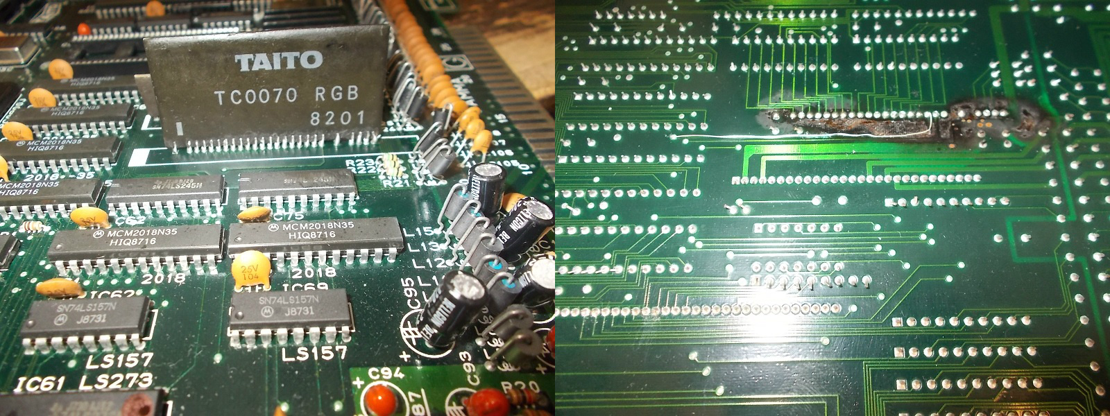
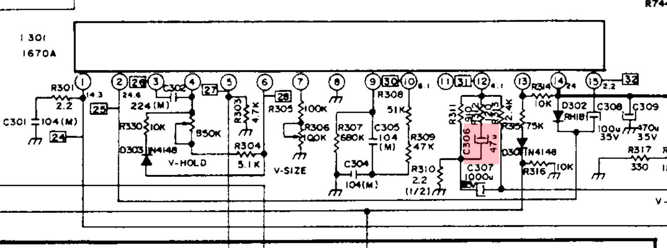
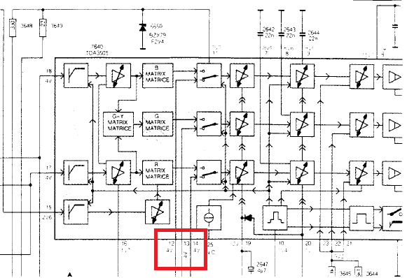
IC502 TDA 3505 pins 12, 13, 14 are RGB in from Euro Connector /SCART, check voltages there to begin with when inputting a perfectly white screen. Then follow the voltages through to transistors TS604 – 606.
The schematic shows the analogue inputs go directly from the RGB connector to the Philips TDA3505 IC via some 100nf caps. Pins 12,13 & 14 are the input RGB signals. I measured 4.3v for red and green but 9.1v for blue. That seems a little too high for blue and the schematic indicates 4v for those signals.
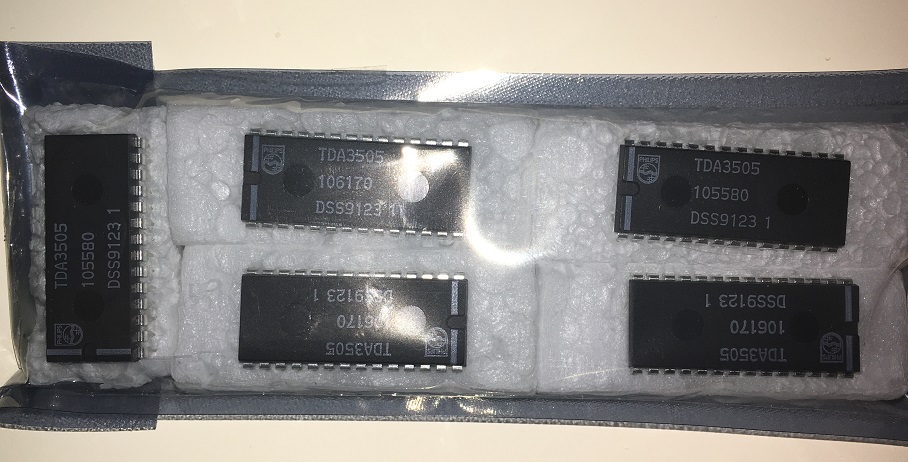
I order some TDA3505s on eBay from atarifreakz and my package arrives a few weeks later.
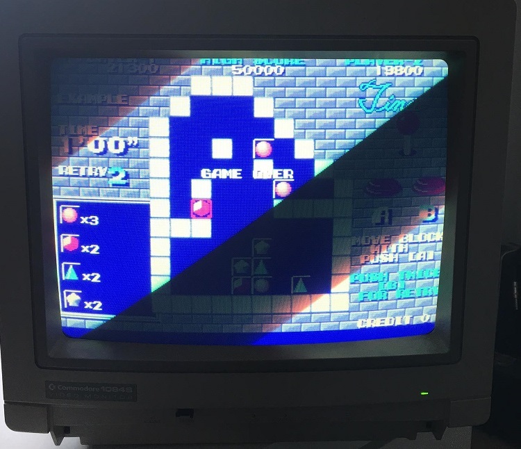
Not wasting any time. I replace the chip and the picture is now perfect!
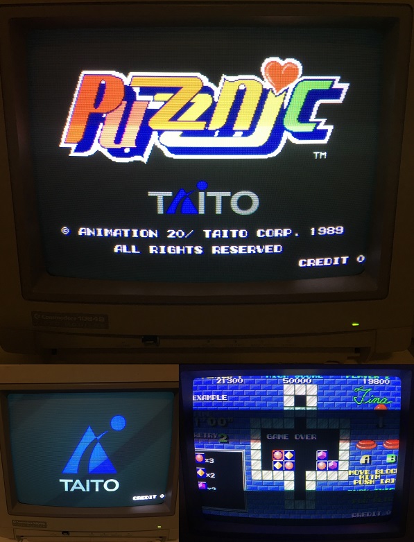
The Taito logo and blue shadow around the Puzznic logo is now visible. Notice the bricks and backgrounds are also showing up right compared with the previous screenshot.
I wonder if there will be a part 4 🙂