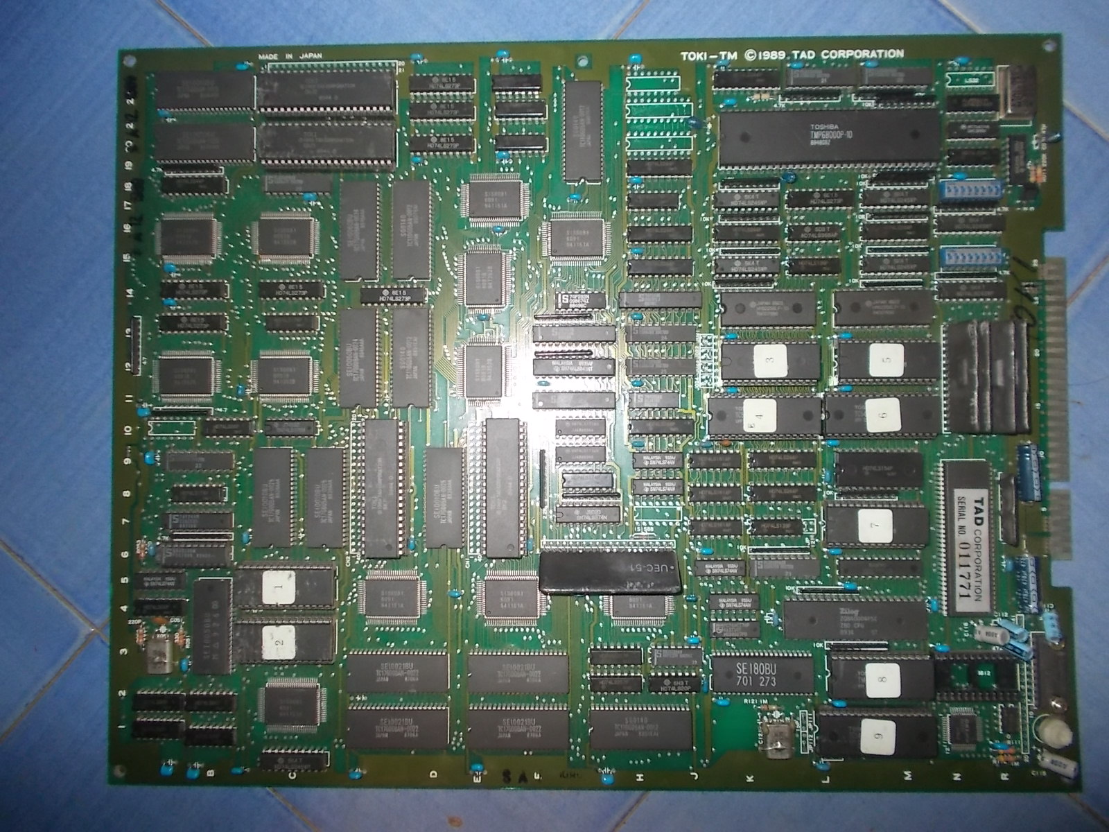
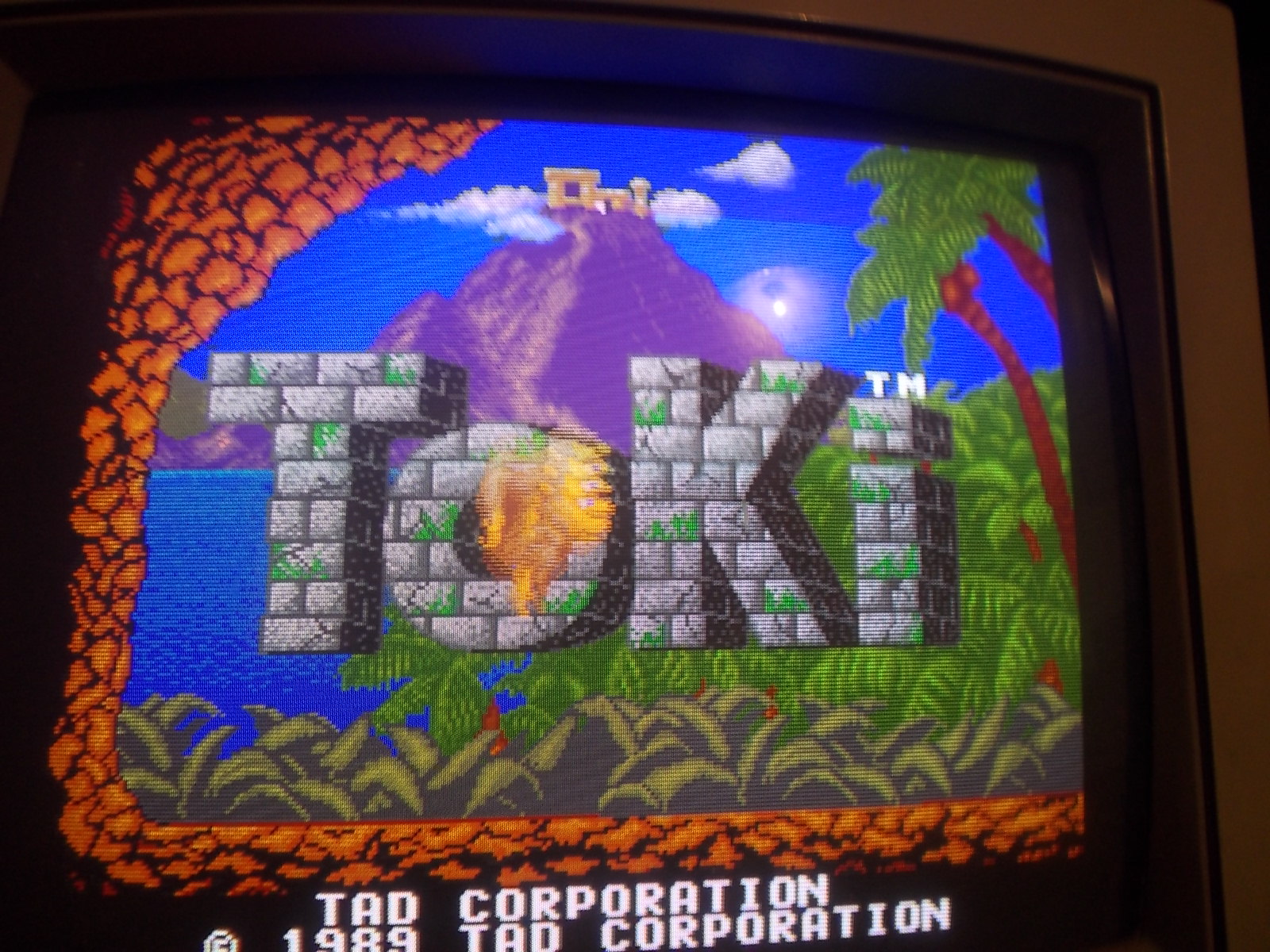
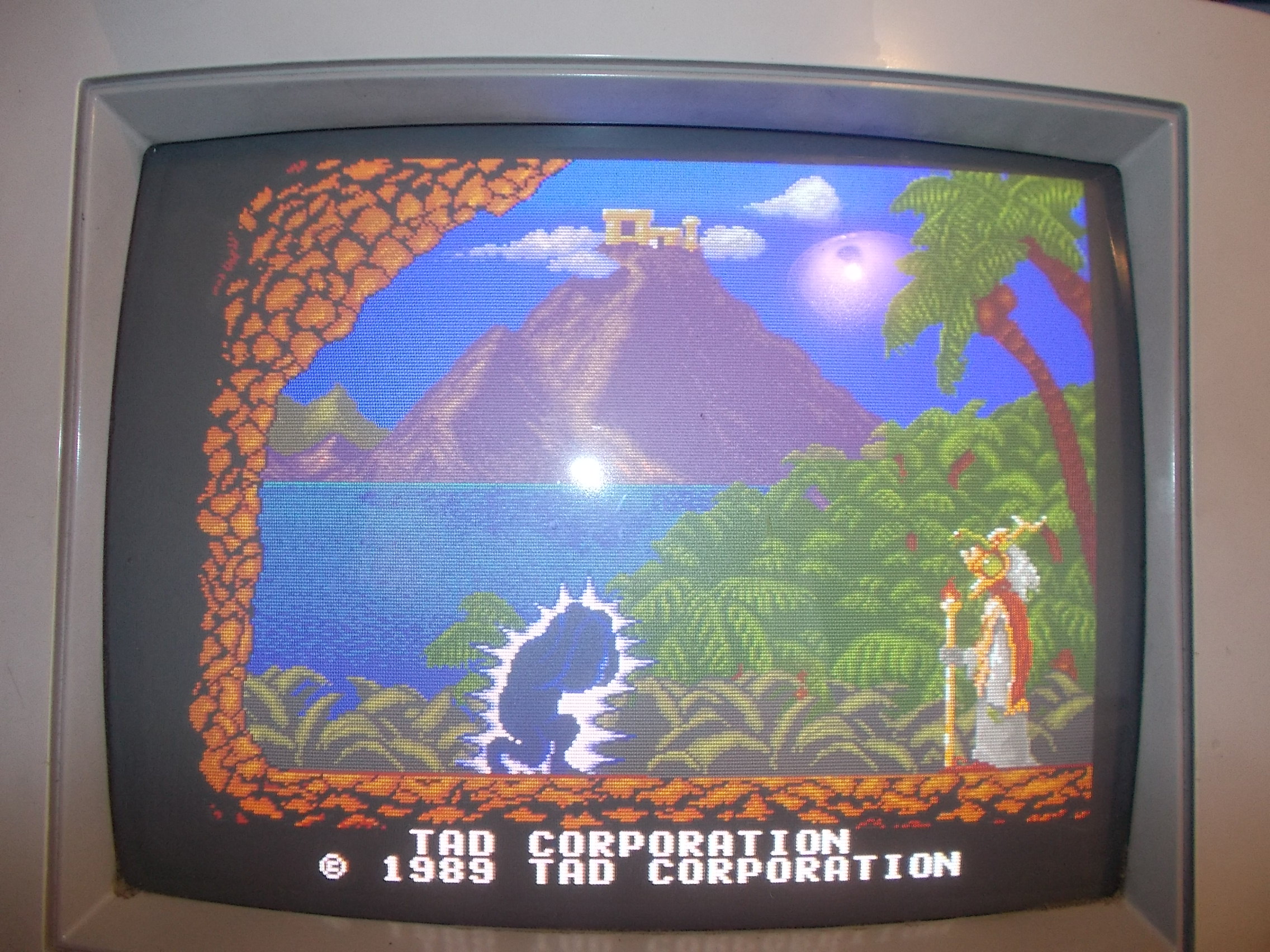
A quick double repair log of Toki, a funny and addictive platform game released by TAD Corporation in 1989.
The first PCB:
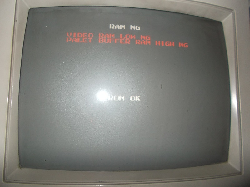
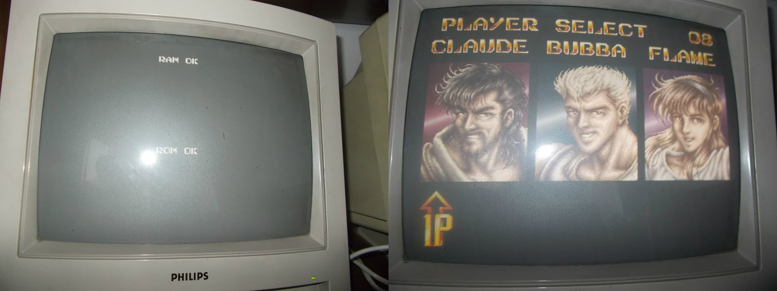
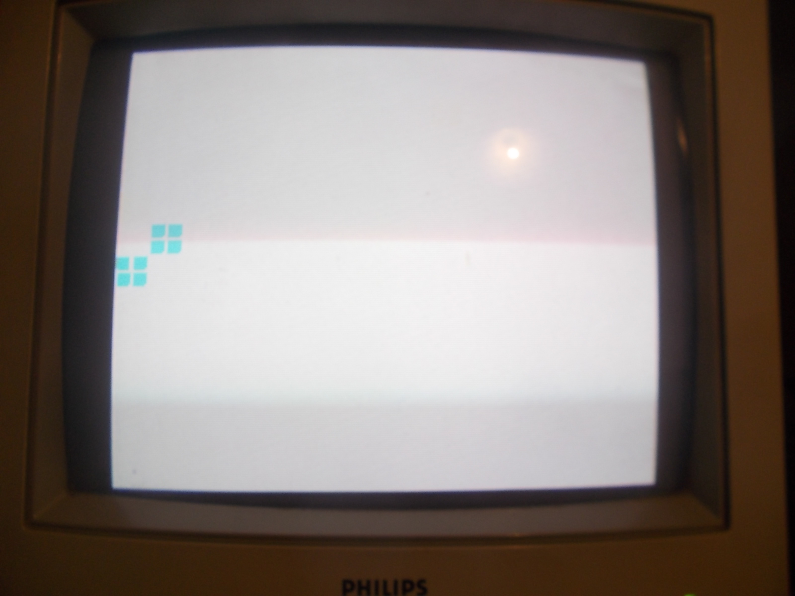
On power up it was stuck on a blank static screen:
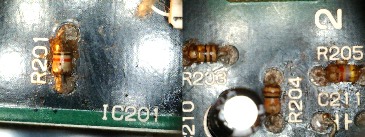
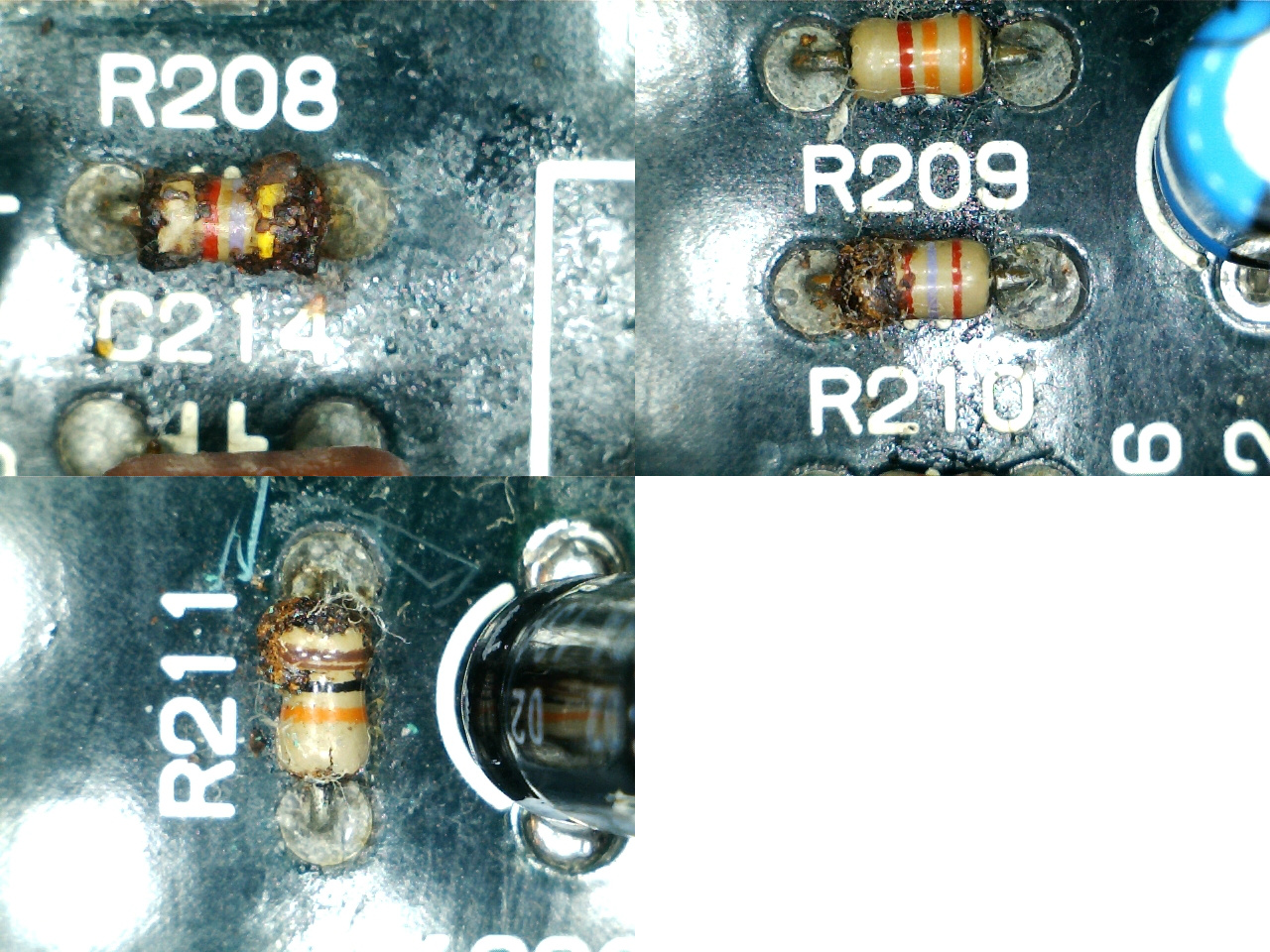
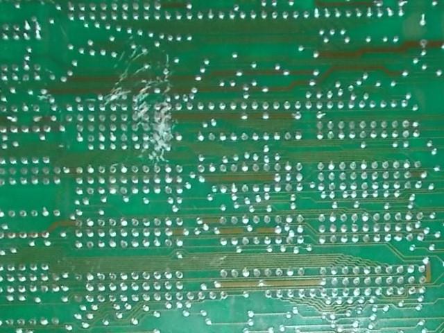
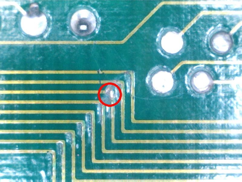
Doing a visual inspection I noticed some scratches on solder side:
Using my multimeter in continuity check I found a couple of severed traces in the 68000 main CPU area:
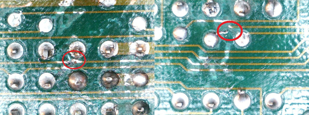
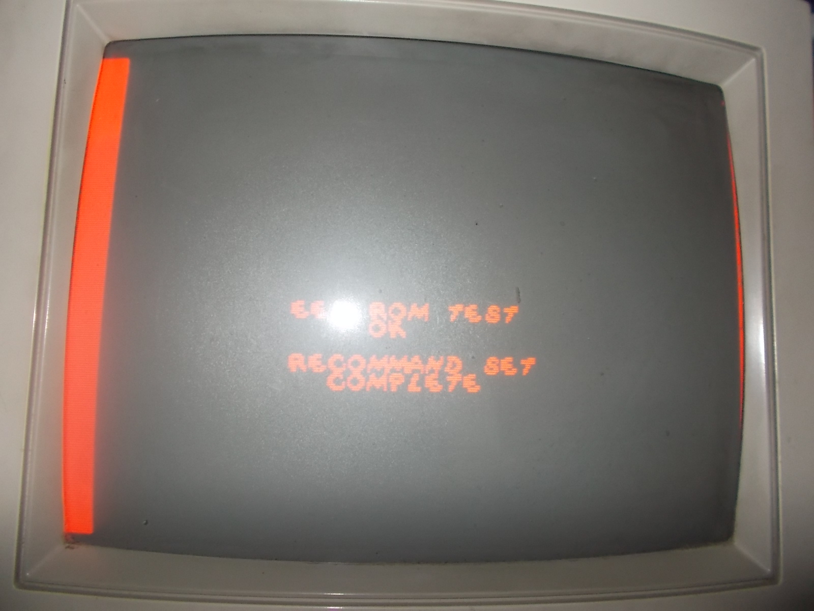
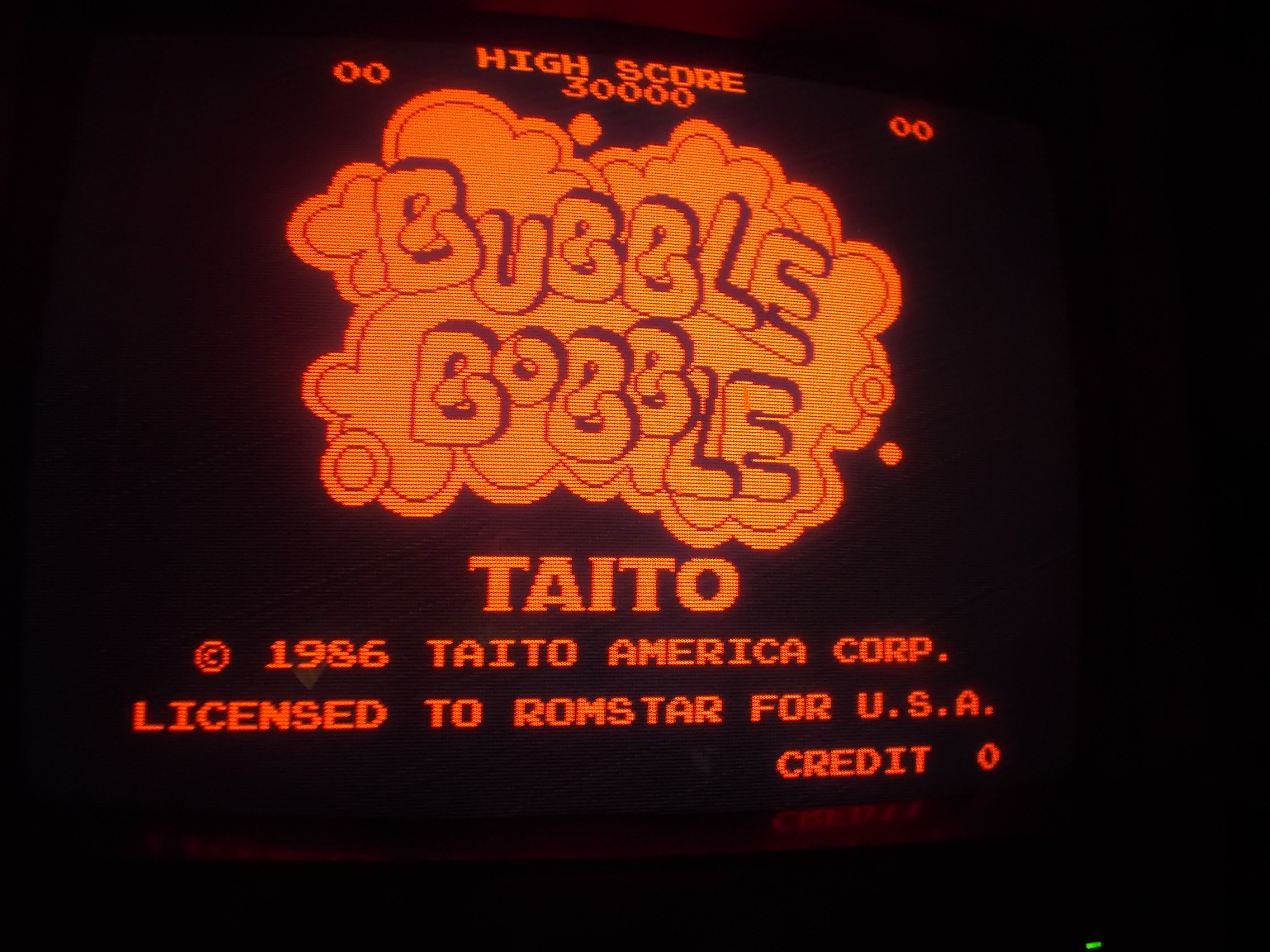
After patched them the game successfuly booted:
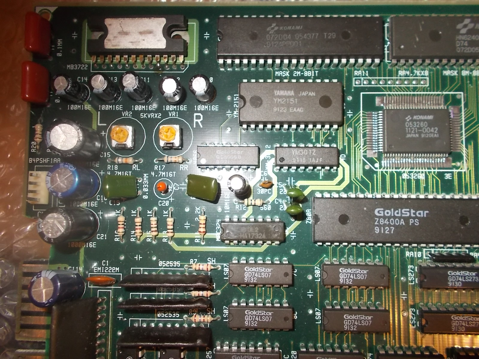
But sound was absent, this was due missing YM3812 OPL chip and custom SIL ‘HB-41’ module:
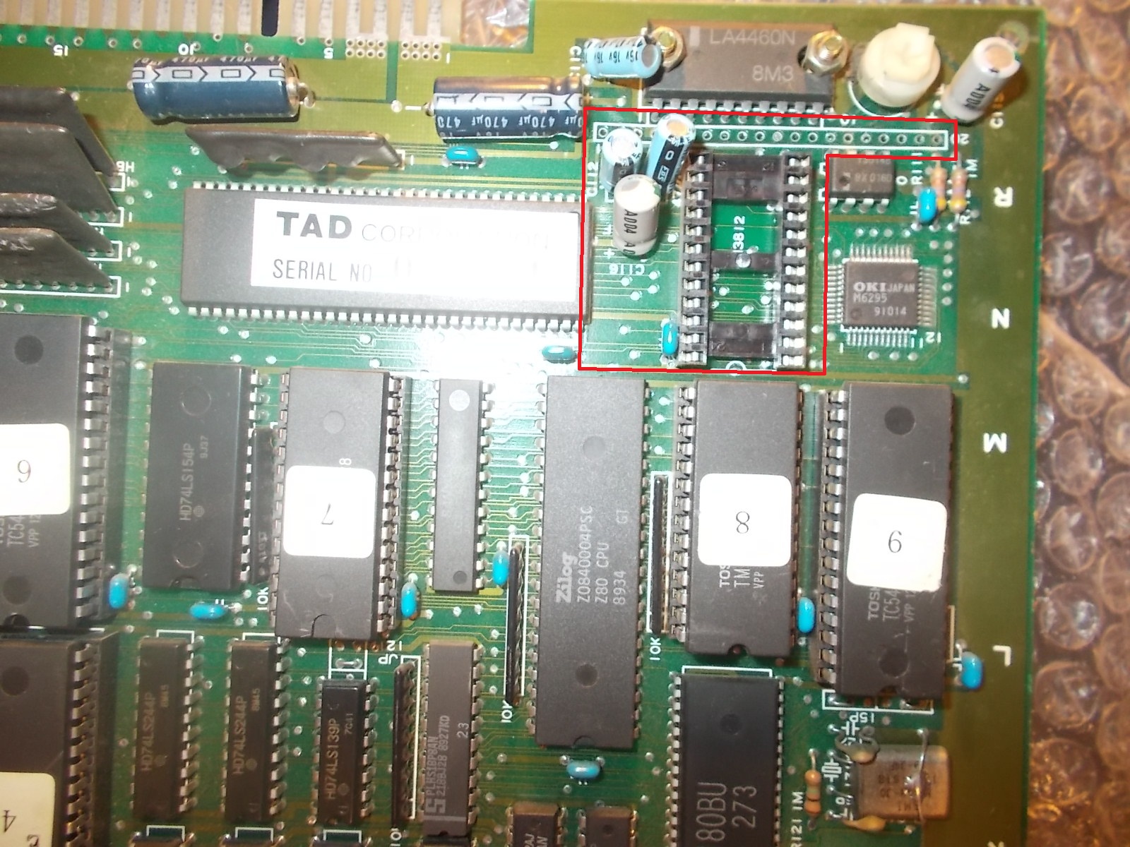
I finished the repair installing the missing components, this restored full sound.Board 100% working again.
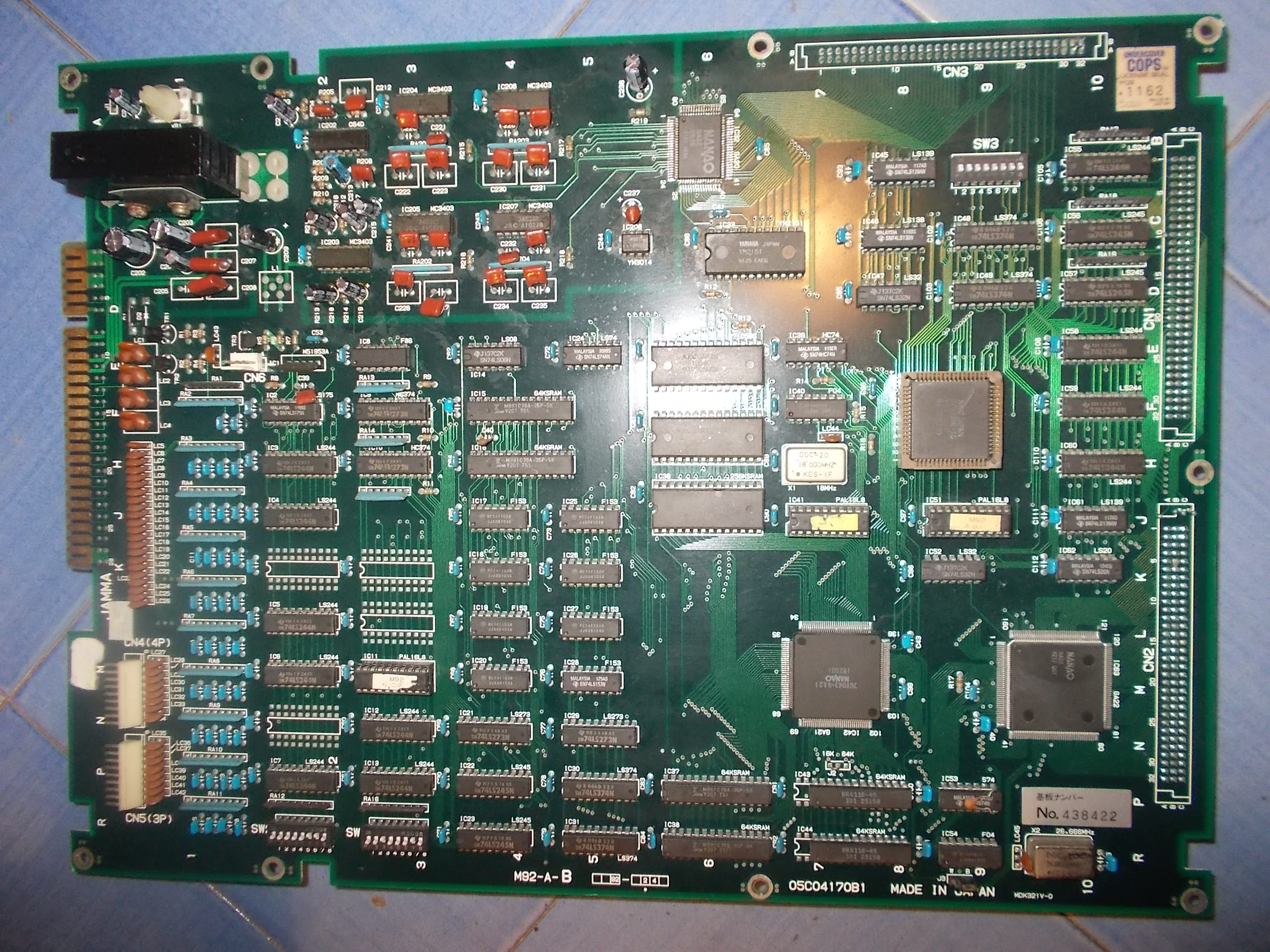
The second PCB:
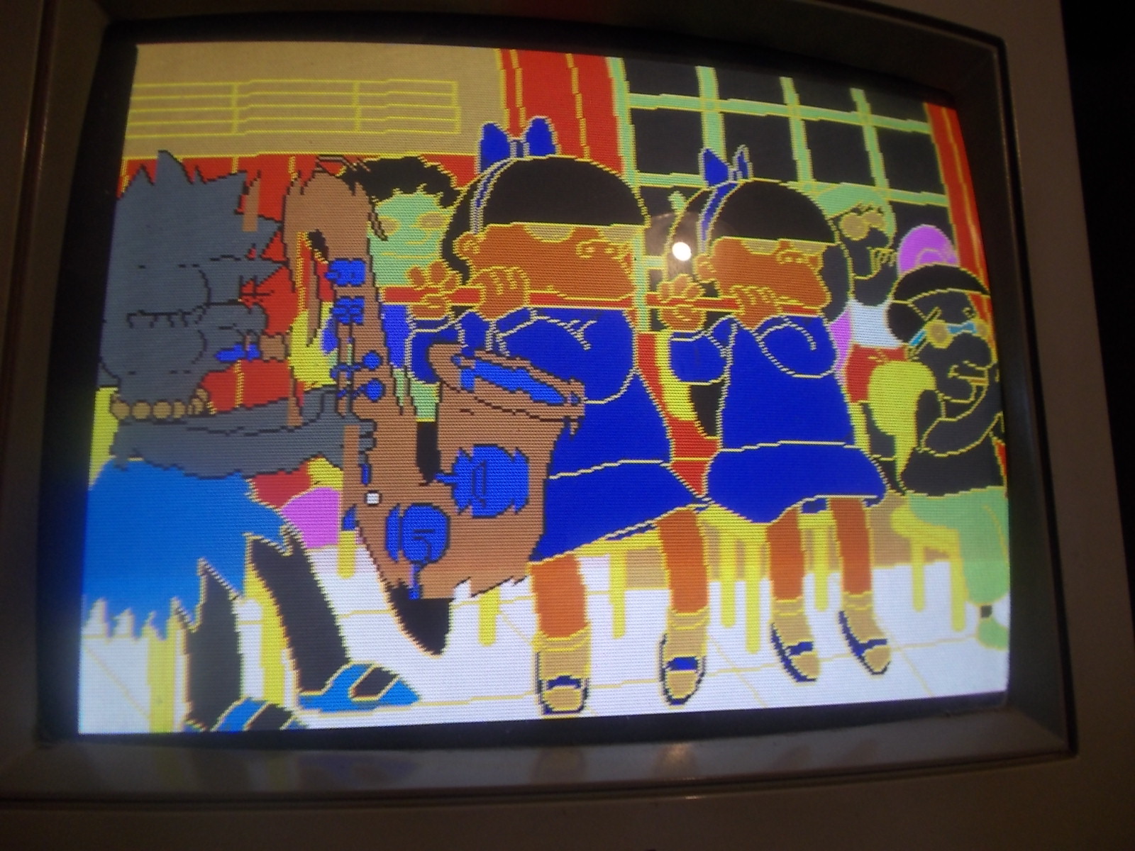
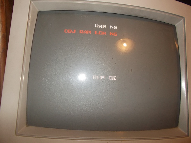
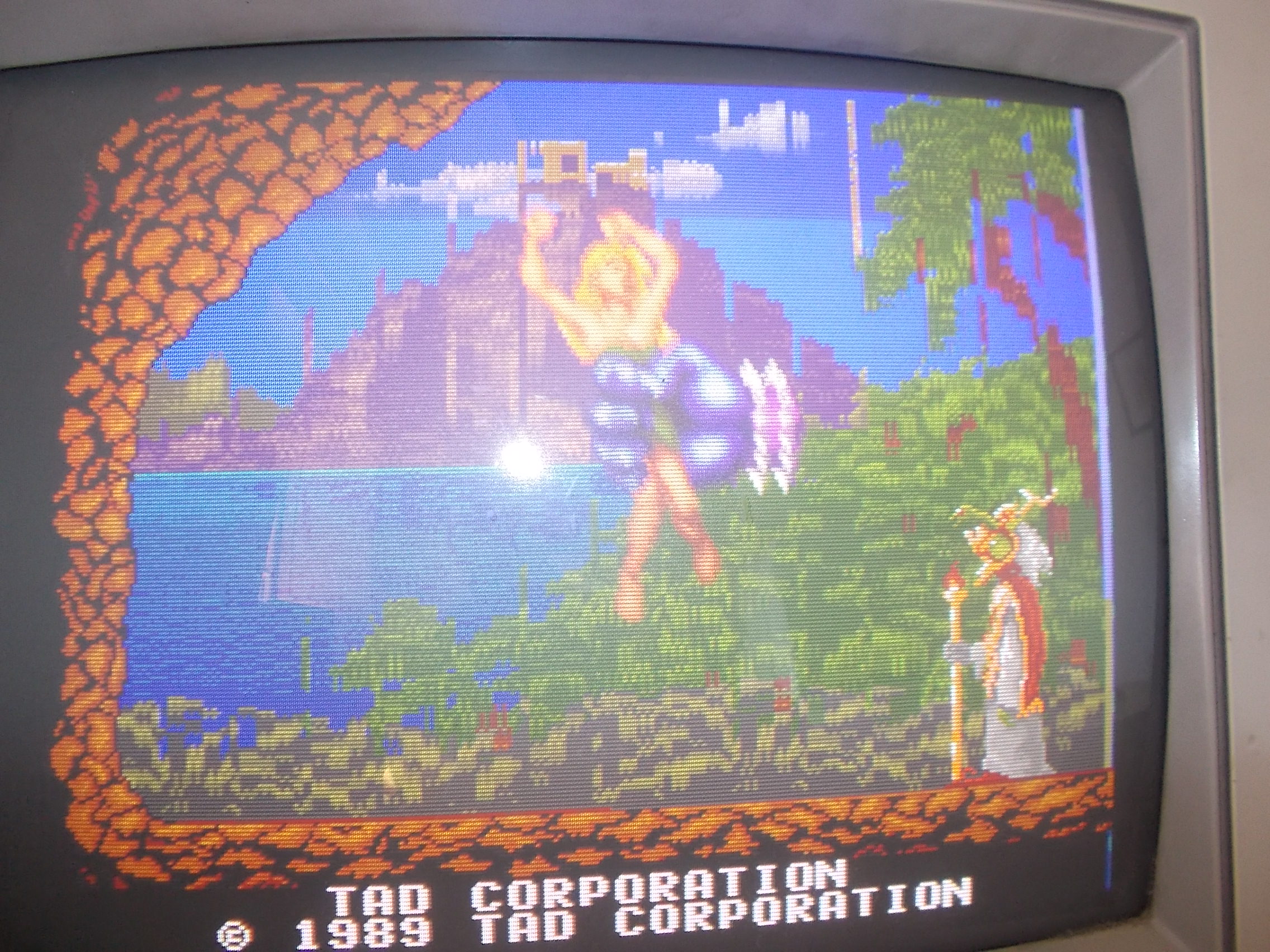
Board booted but backgrounds graphics were corrupted and flashing :
Also here I found a broken trace on solder side:
This restored graphics:
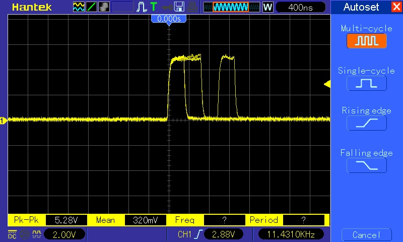
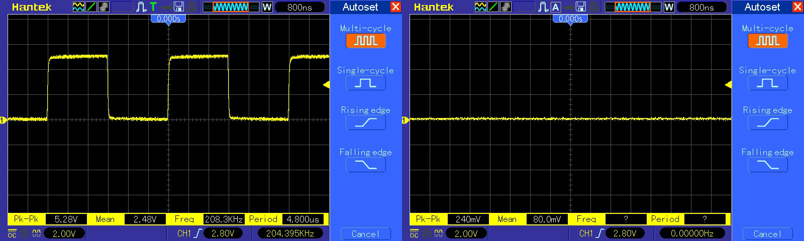
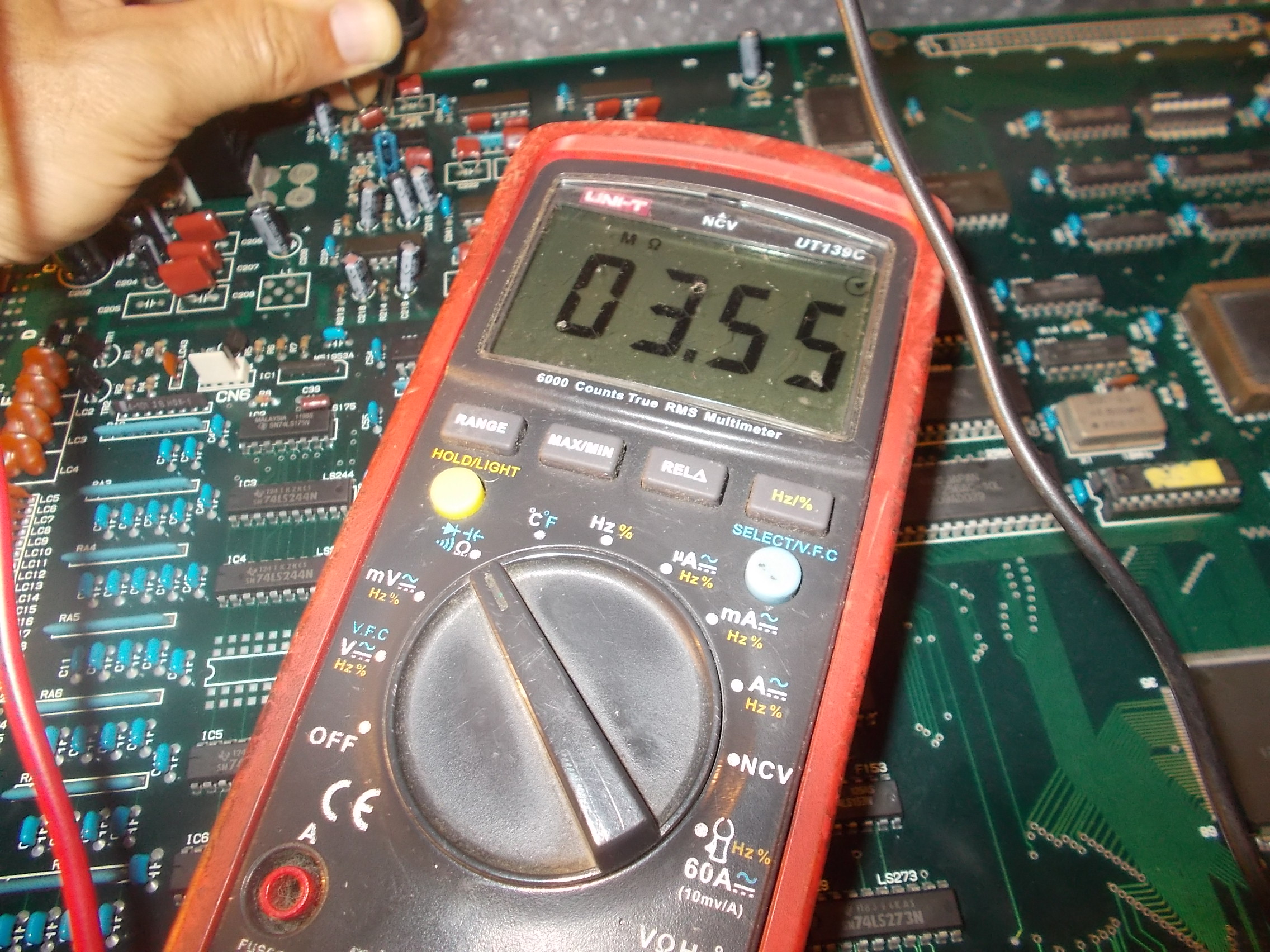
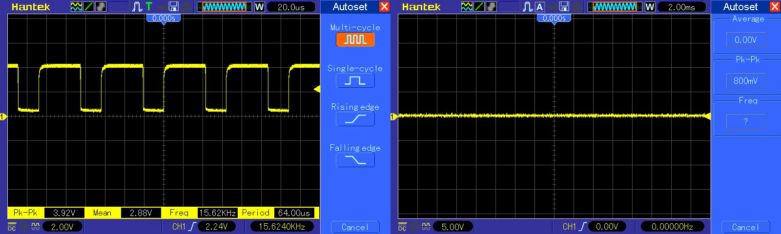
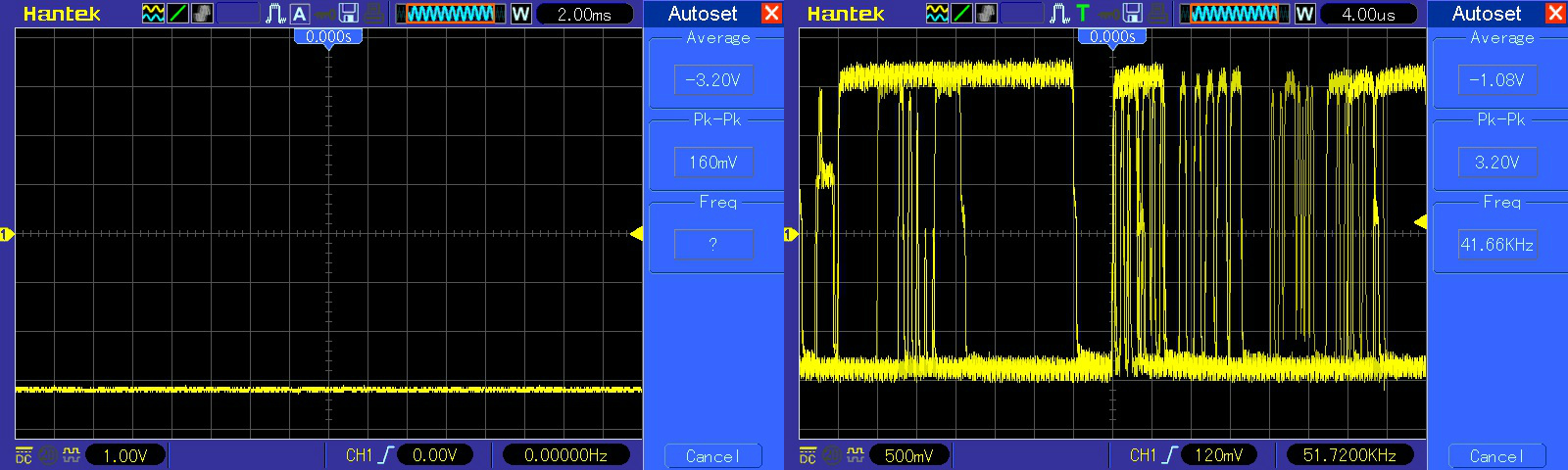
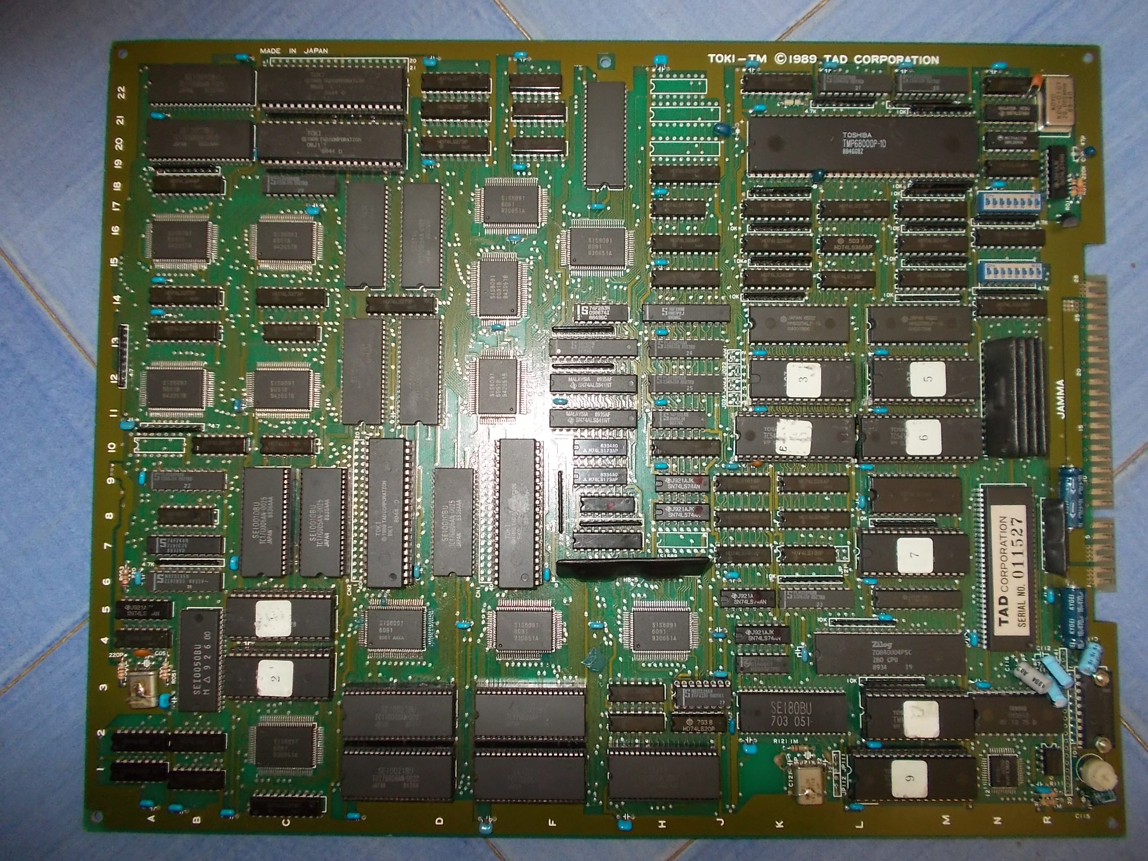
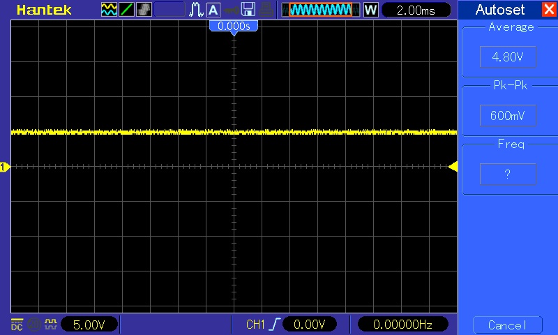
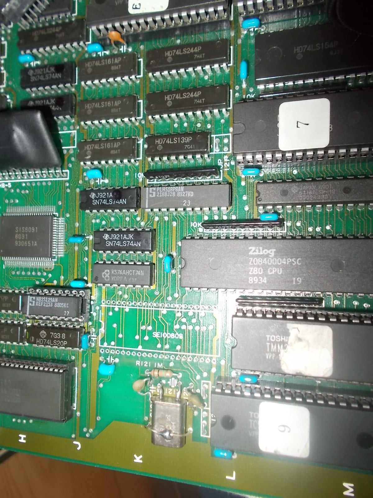
But, while I was testing the board, suddenly I lose sound and I could no longer coin up.The two issues are related each other since on this hardware the Z80 CPU commands the sound system but also handles coins.Indeed, probing it revealed a stuck signal on CLOCK pin 6 where a 3.579545 MHz one should be:
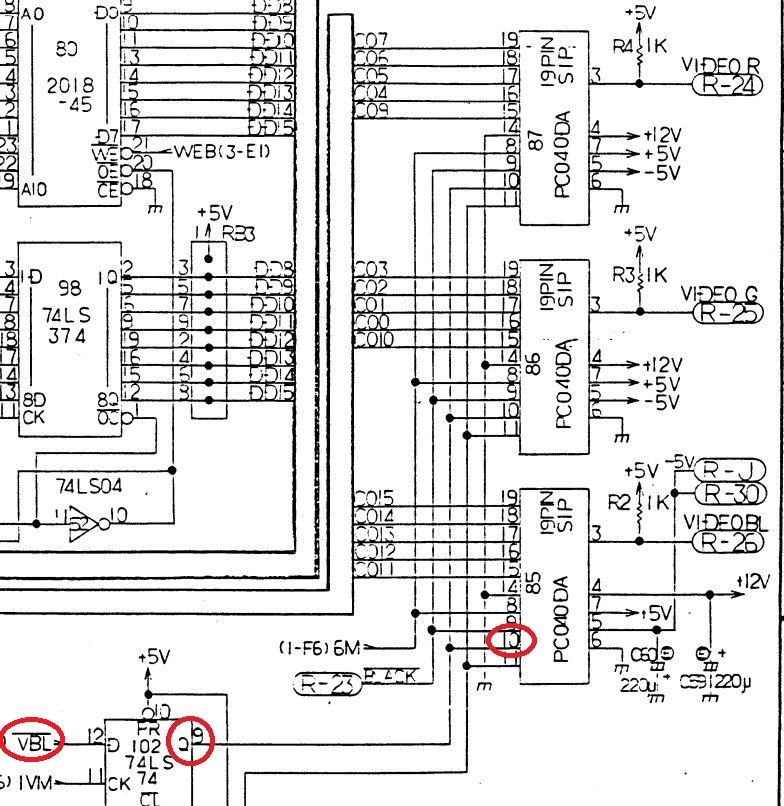
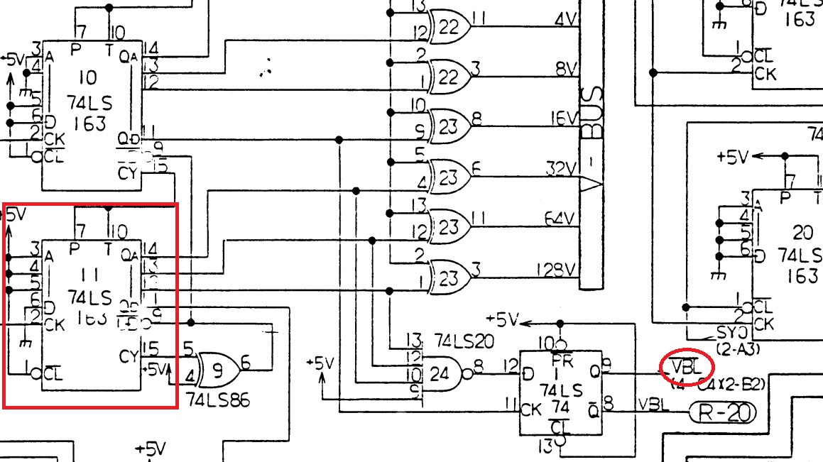
Looking at hardware, the clock is derived by a 14.318 MHz quartz then divided by the custom ‘SEI80BU’ (which also does interface between main and sub CPU) and lastly divided again by a 74HC74 (14.318/4= 3.5795)
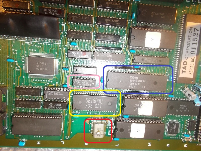
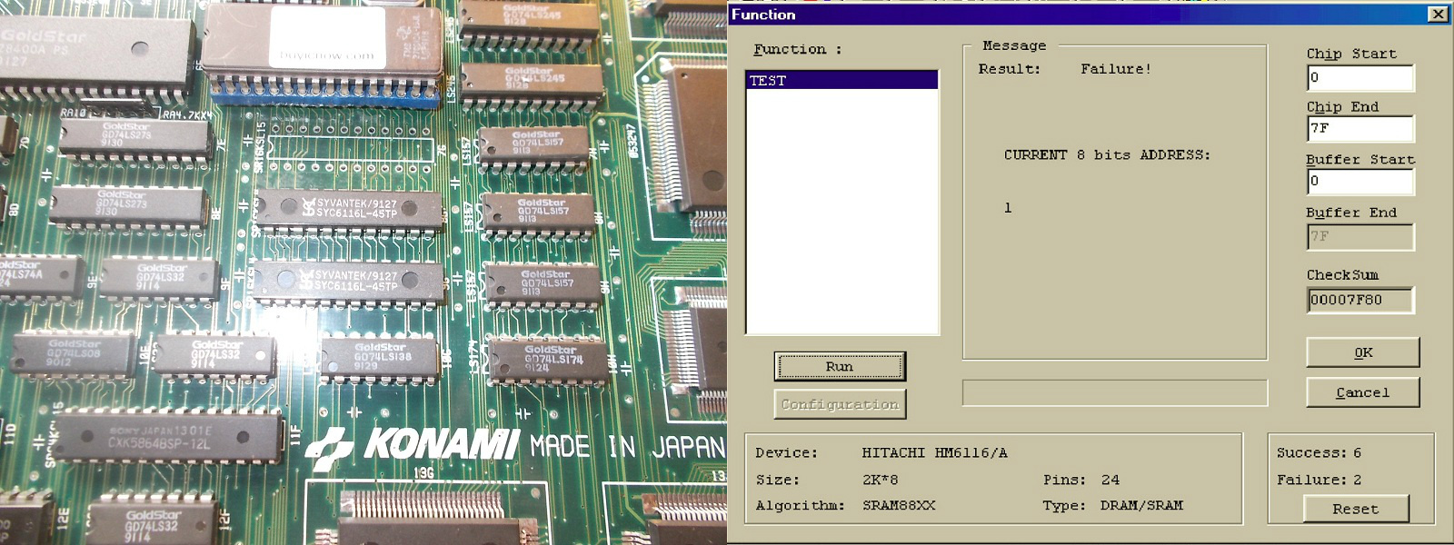
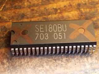
I replaced the quartz with no luck , the 74HCT74 was not receiving any 7.159MHz signal so, for exclusion, the ‘SEI180BU’ had to be the culprit.I removed it and took the spare from a scrap Raiden PCB:
This restored sound hence the custom was really bad:
Double repair accomplished.