Hello,
This is my first repair log on an arcade board, i hope that my text will not be too long and useful to anyone having problems with their own PCB of the same game.
The preambule of this repair :
First thing first, i bought this PCB sold as broken with repair required, paid 130 euros.
On reception :
After pluging the board on my jamma system, i noticed that the board has at least 4 problems to fix.
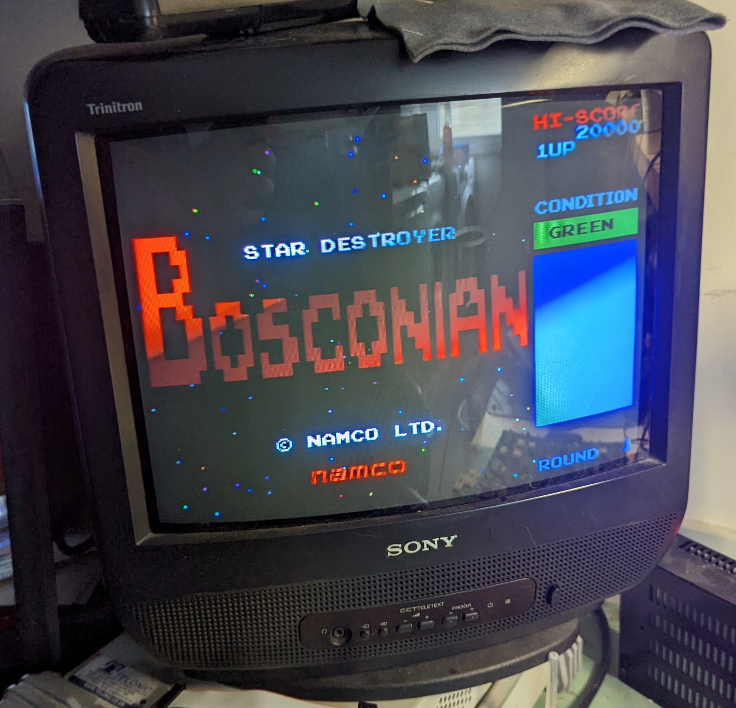
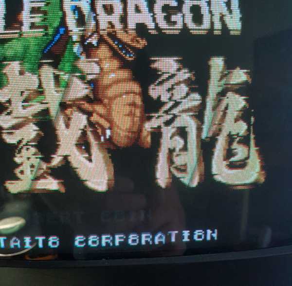
The first is that i get japanese characters on screen. After reading each eproms and socketed maskroms, i see that FU-05 is from the wrong set. The solution was easy peasy : i bought a 27512 brand new on ebay, and burn the right content from the world set.
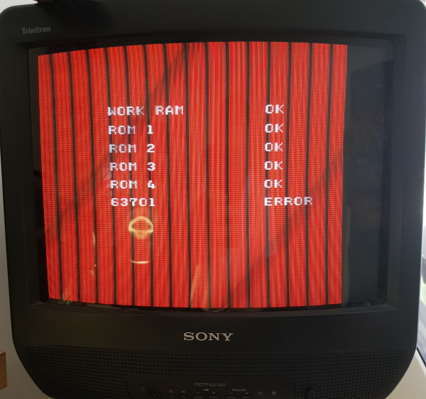
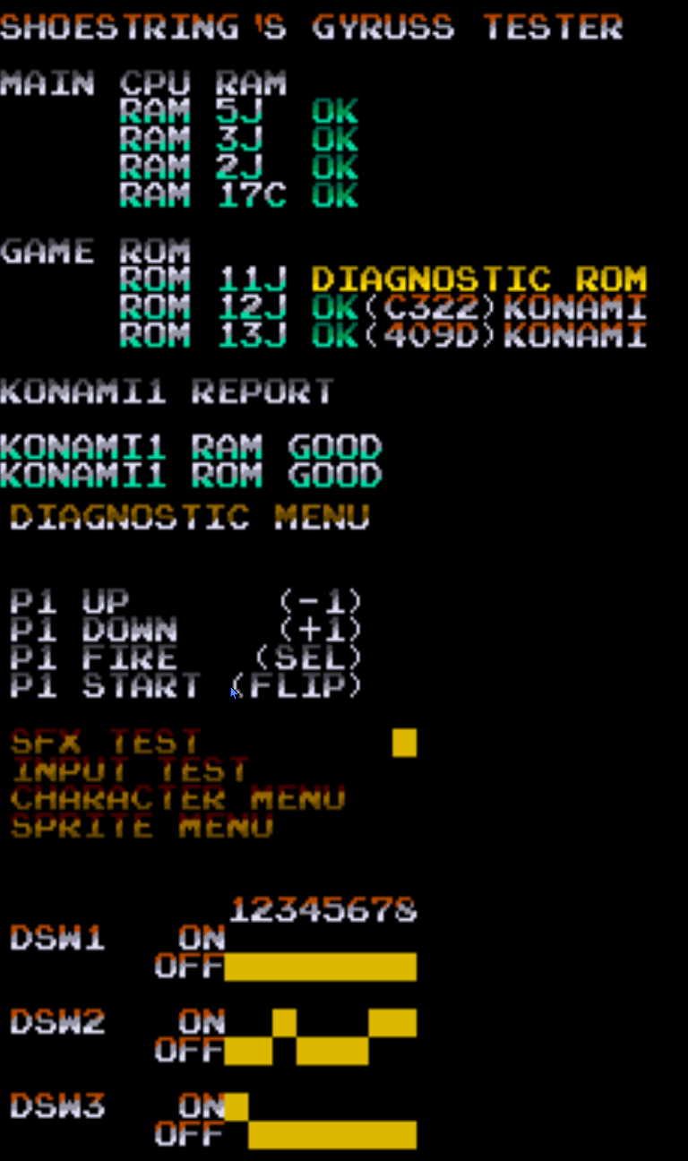
Once this first problem is fixed, i get this screen :
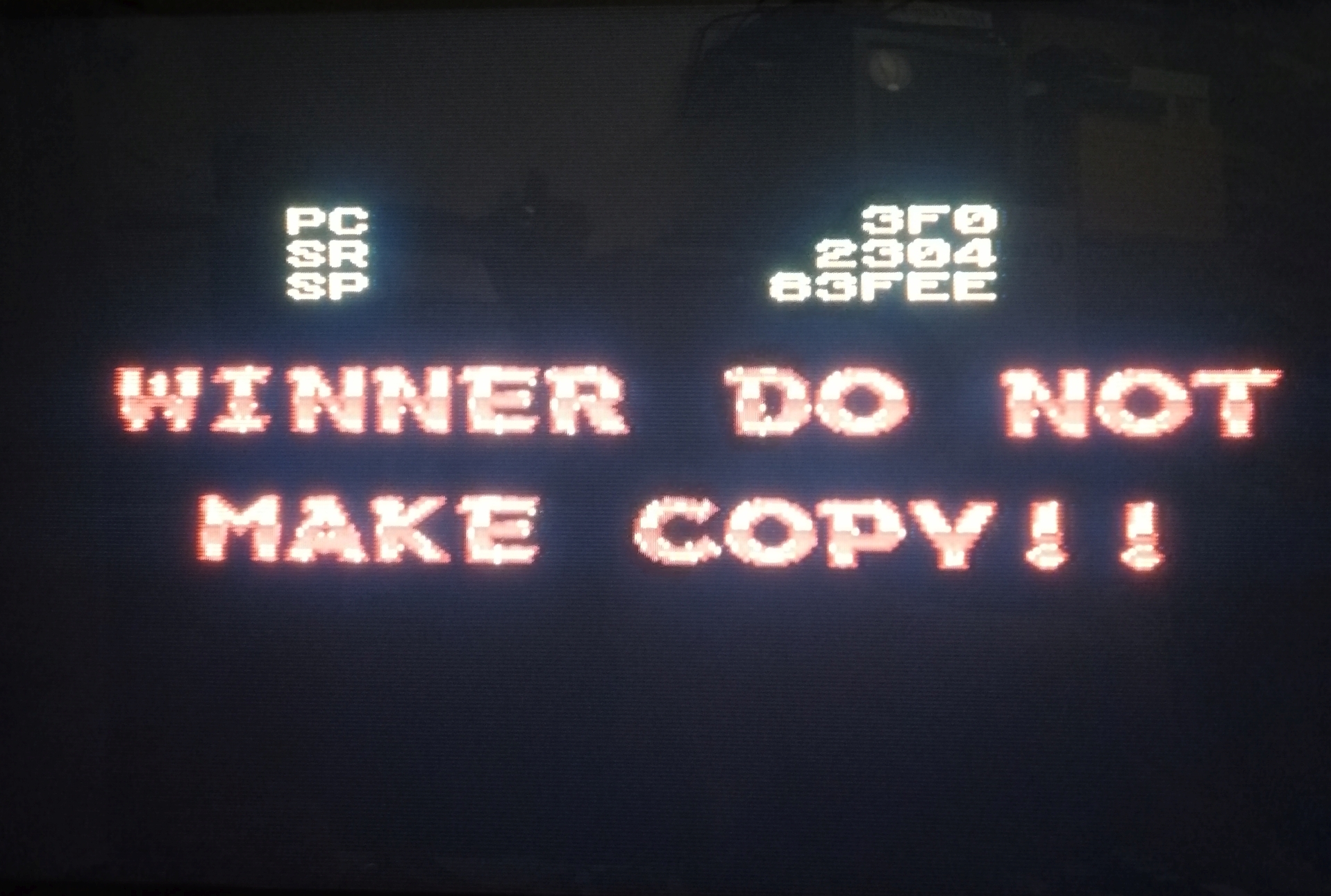
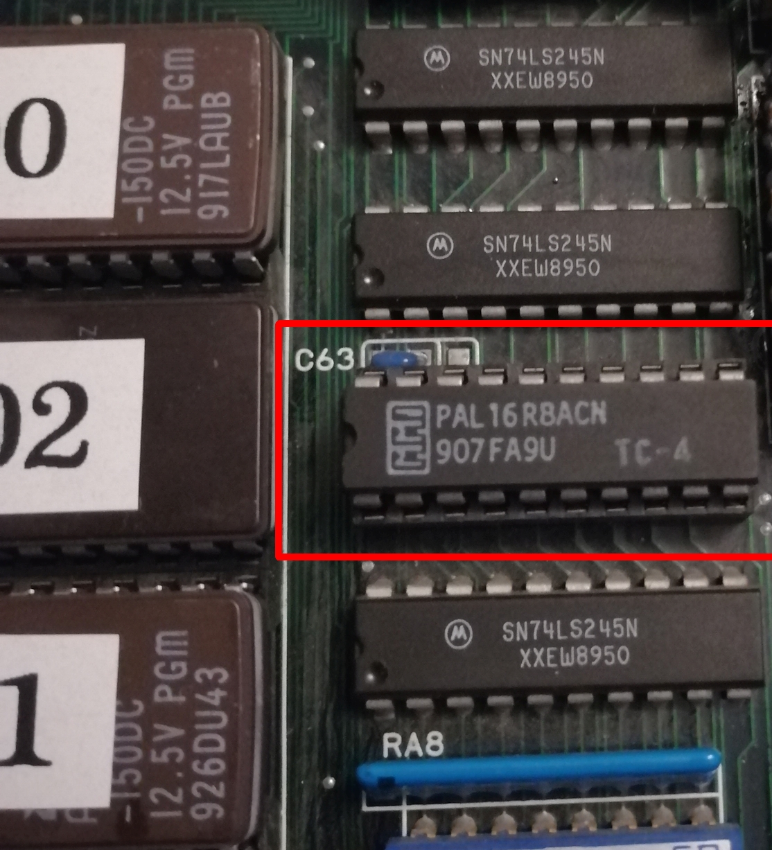
This error has already been solved by Porchy, this message appear when the routine that check the presence of the TC4 PAL chip fails. It indicates that the TC4 chip is wrong or toasted. And indeed, by checking with the magical finger touch, the chip is very hot.
So as a solution, i bought a replacement GAL 16V8 on ebay :
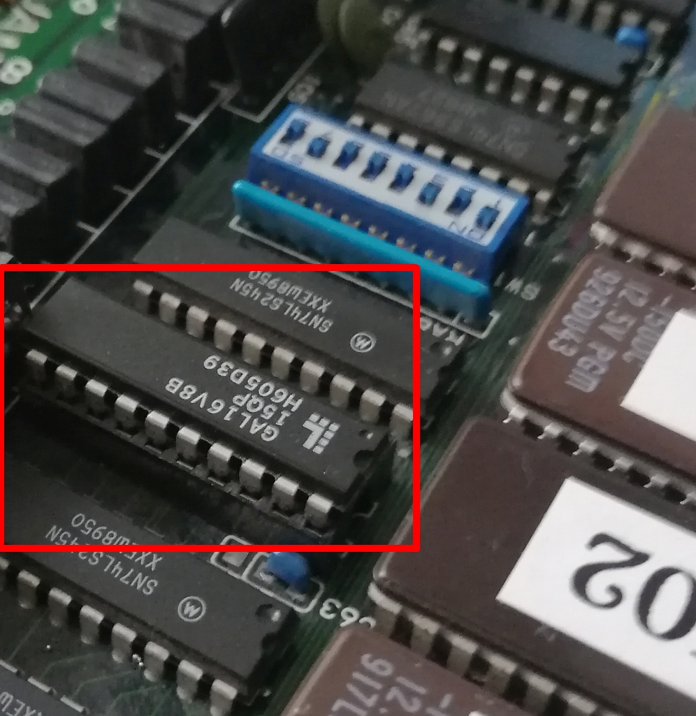
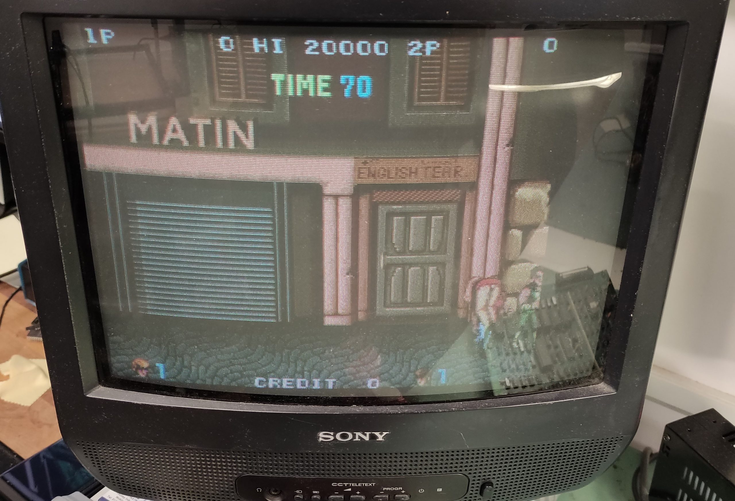
Now, the game boot correctly.
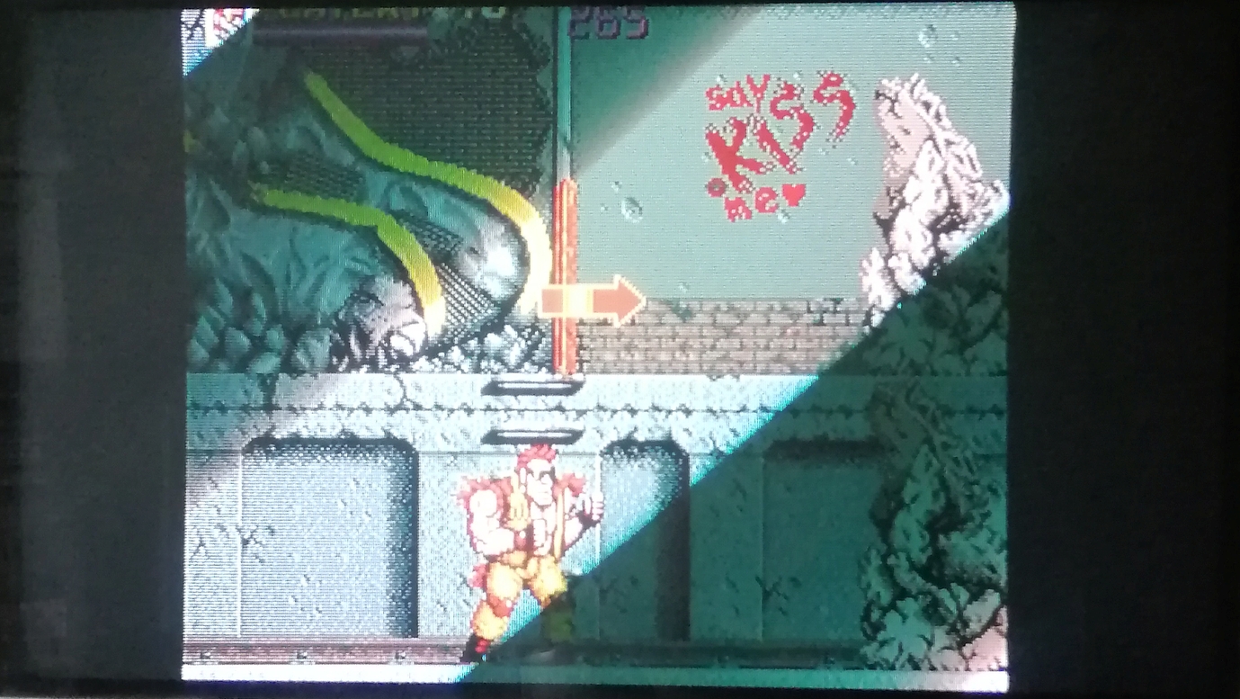
Let’s check the next problem to fix :
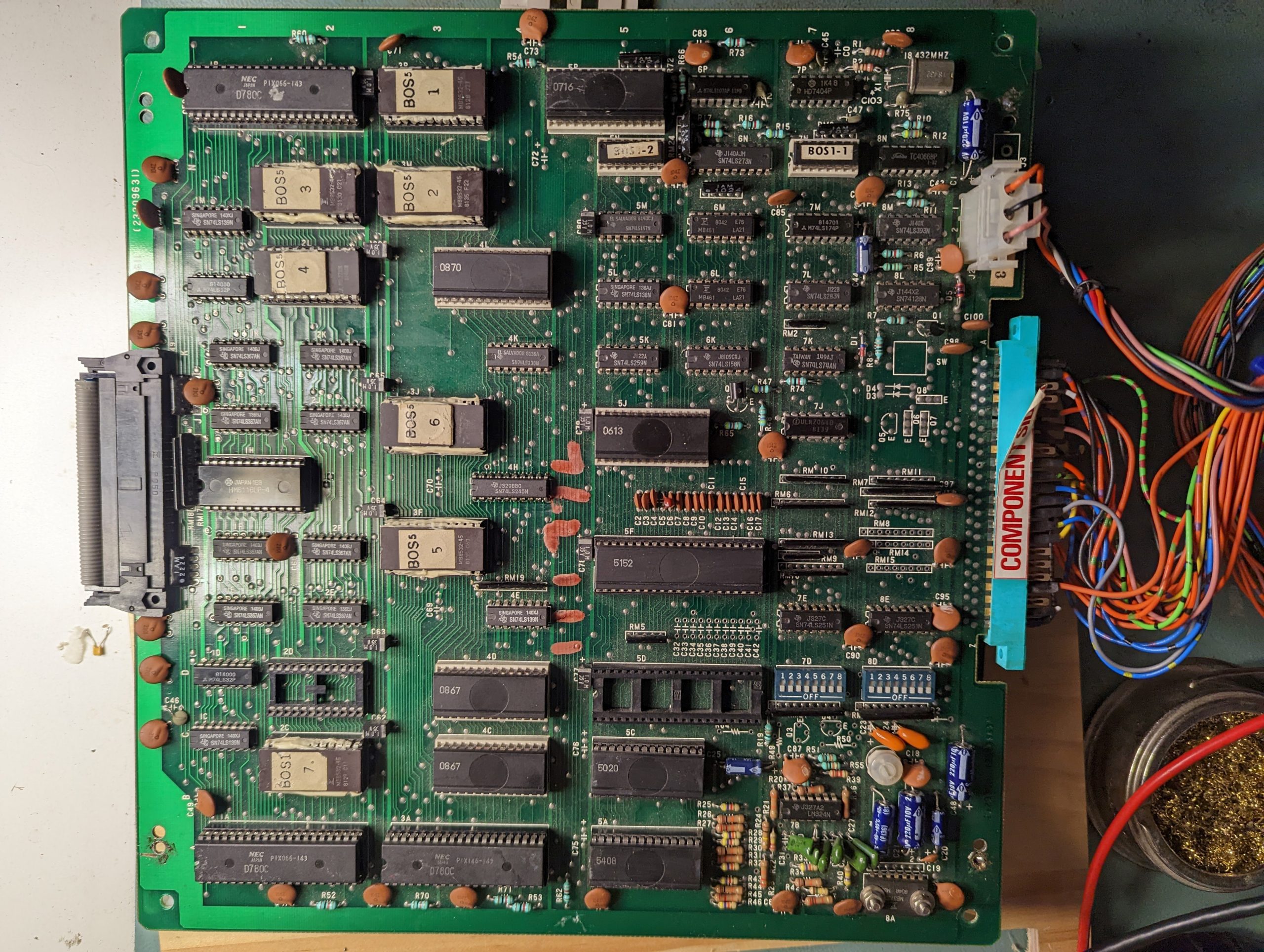
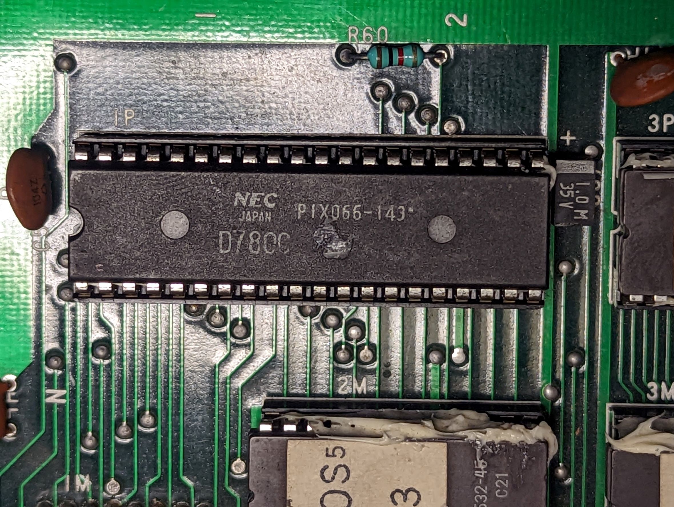
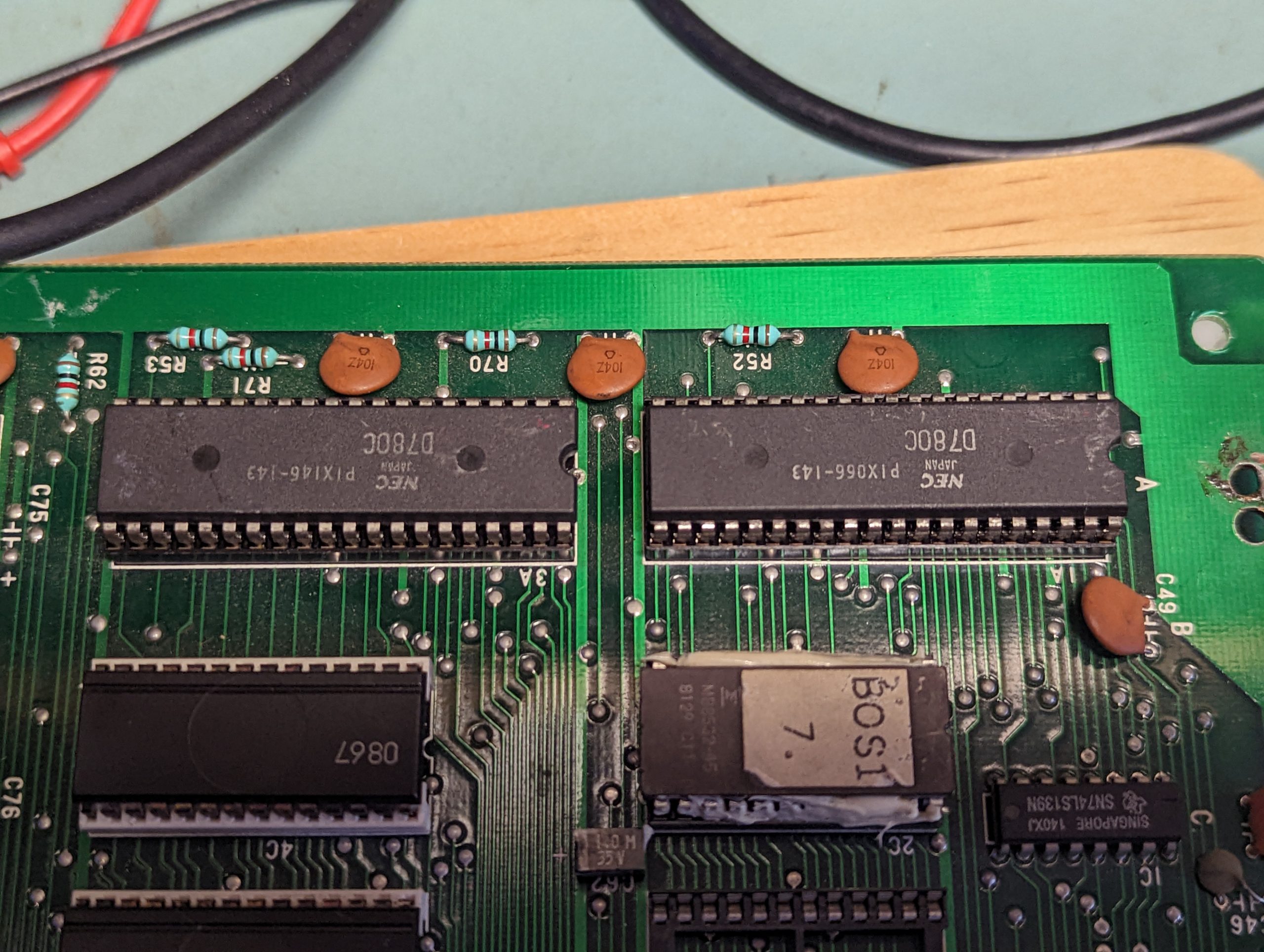
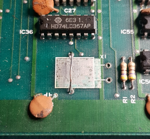
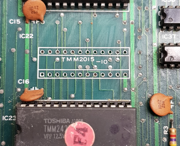
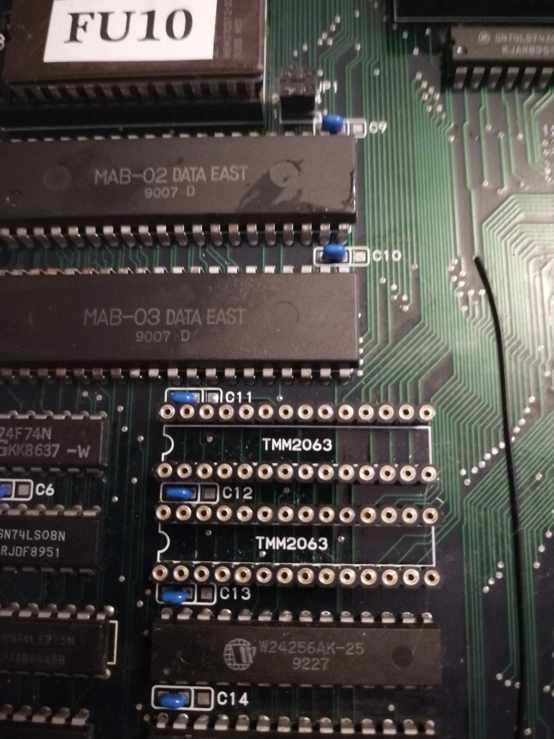
I see that the graphics are simply flashing constantly on the screen, it’s a mess. The culprit are the sram located here :
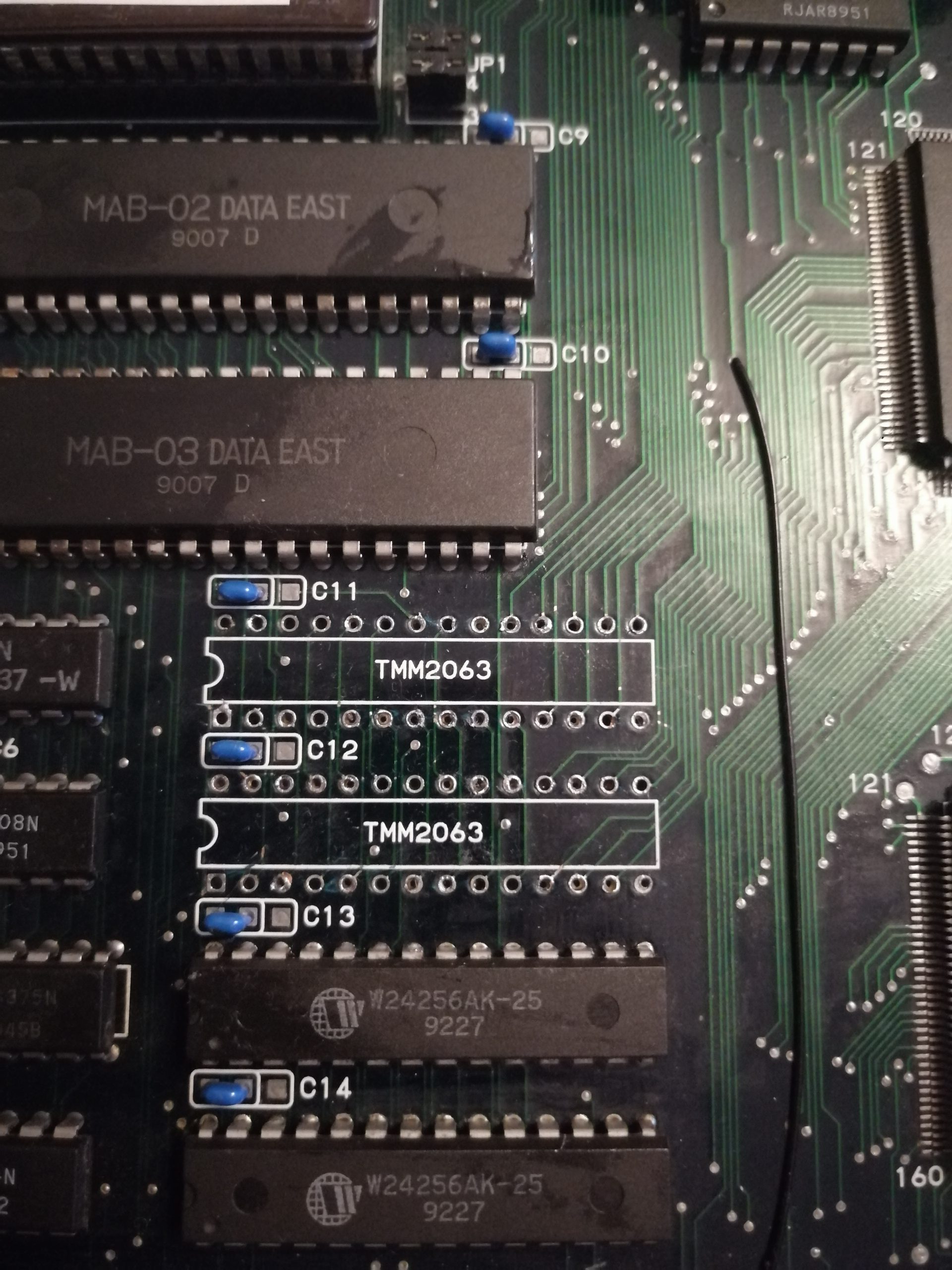
Those are TMM2063, and when i passed my finger on them, they were incredibly hot on touch, and the graphics were going crazy on screen. In order to confirm they are shot, i piggyback with new sram replacements bought on ebay : graphics are now fixed !
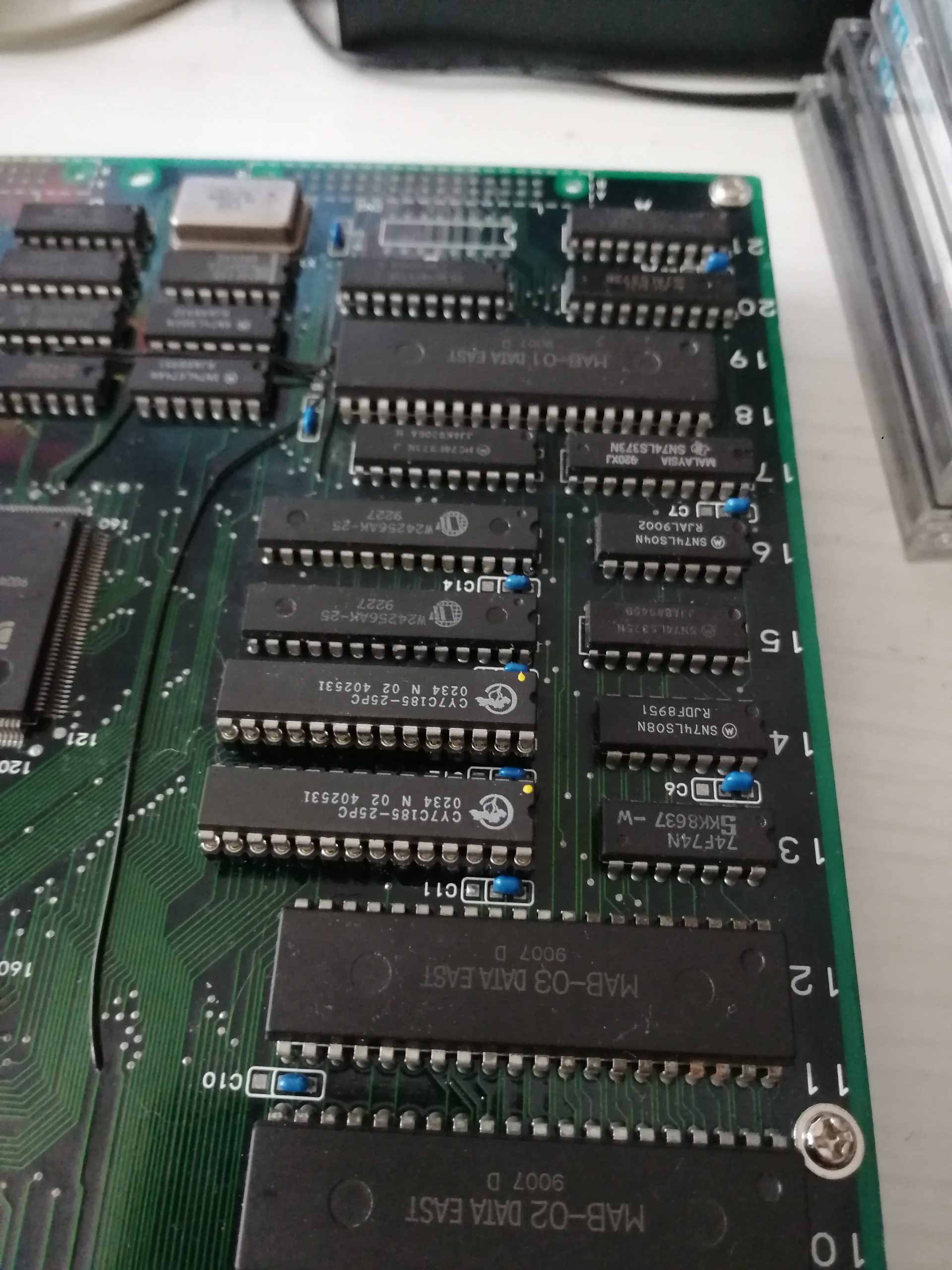
Let’s remove the buggers :
And install the brand new SRAMs :
Last problem to fix :
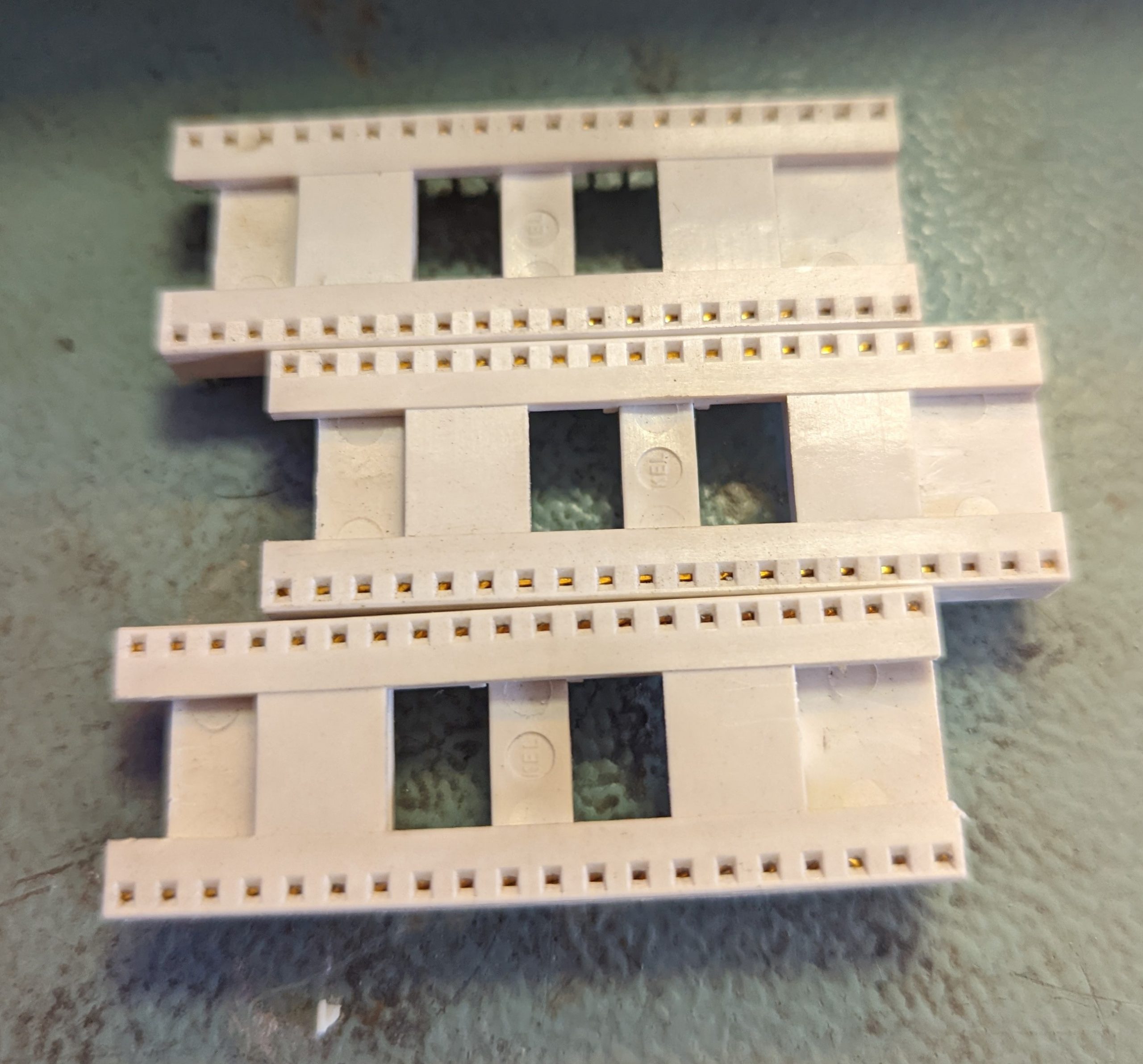
I noticed that jump button and start button for PL1 are not working. this board seems to have been connected backwards, so the RC1 custom components are shot. So i contacted Caius, who sold me 4 replacement RC1 pcbs, that i replaced on the board :
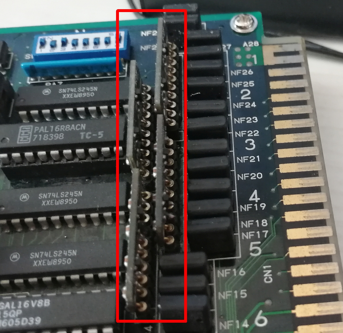
It was not easy to remove properly the dead RC1 components, i got 2 traces cut, that i patched after checking them with my multimeter.
Thanks to Caius on a few tips and hints here and there, the PCB is now fully working.
Another board saved ! 😀
Dlfrsilver
(With many thanks to Caius for the help and the replacement parts).