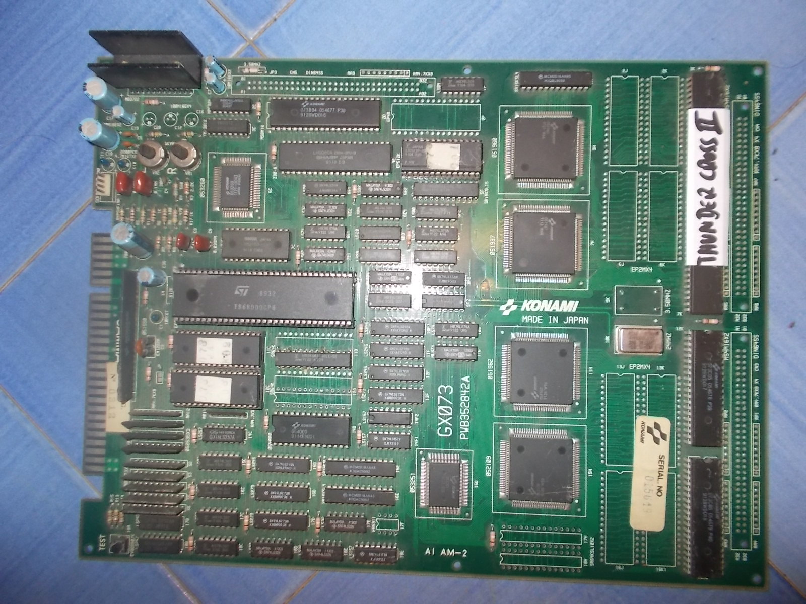
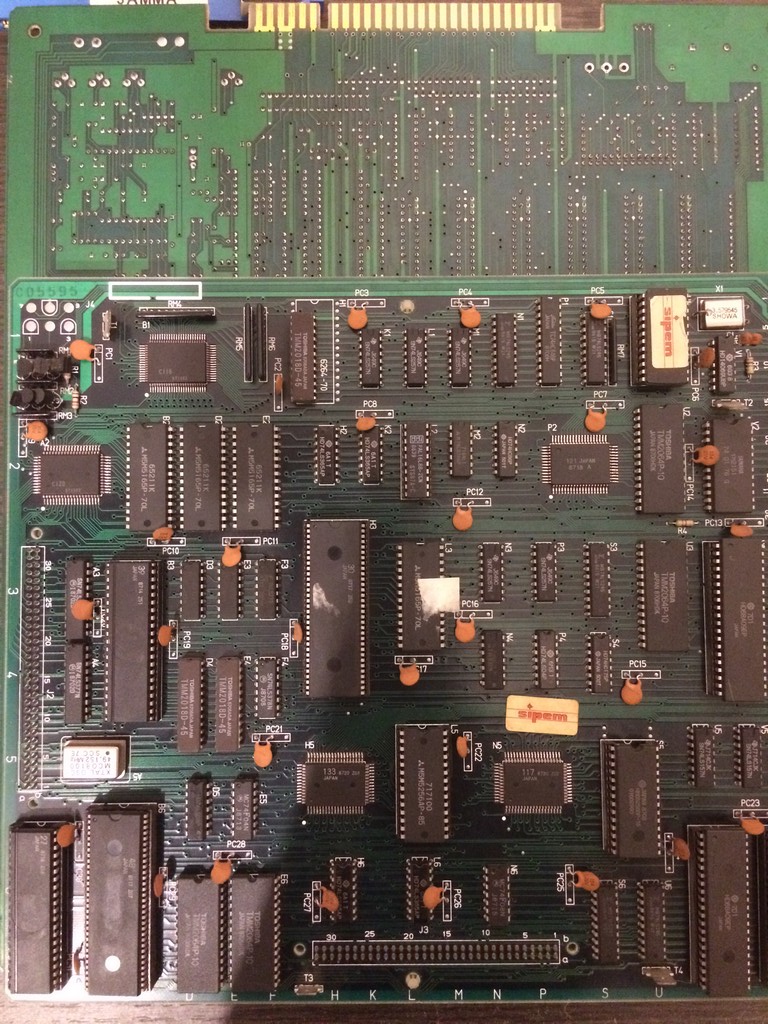
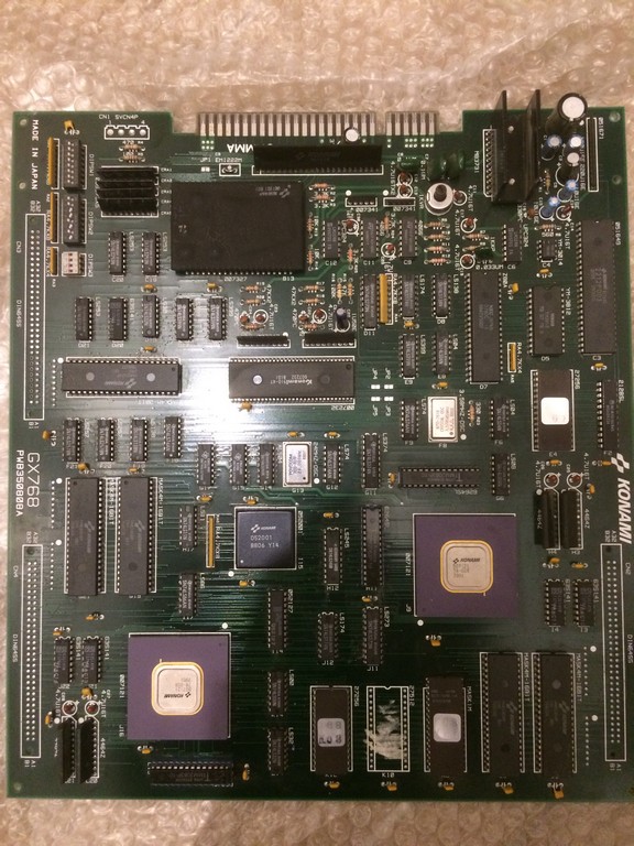
I got this board for my collection as untested from an arcade operator
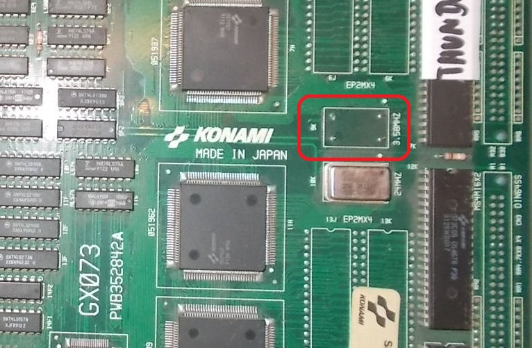
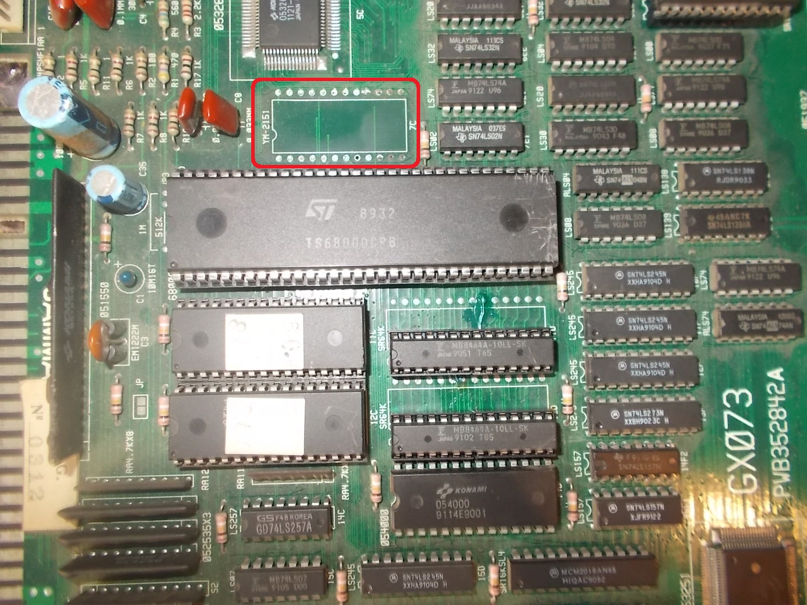
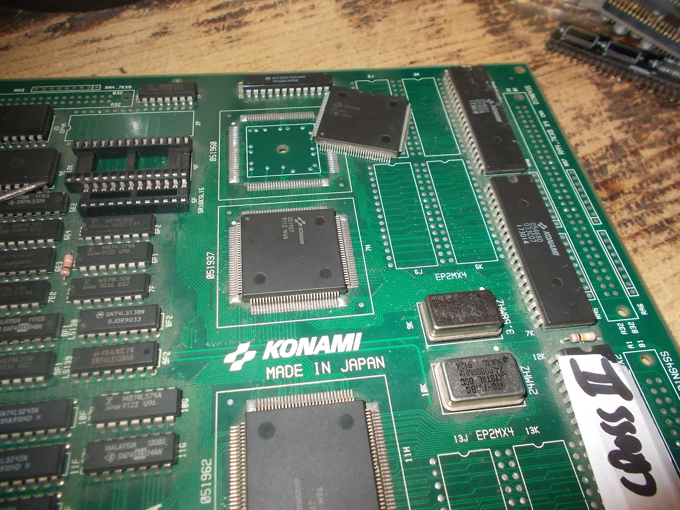
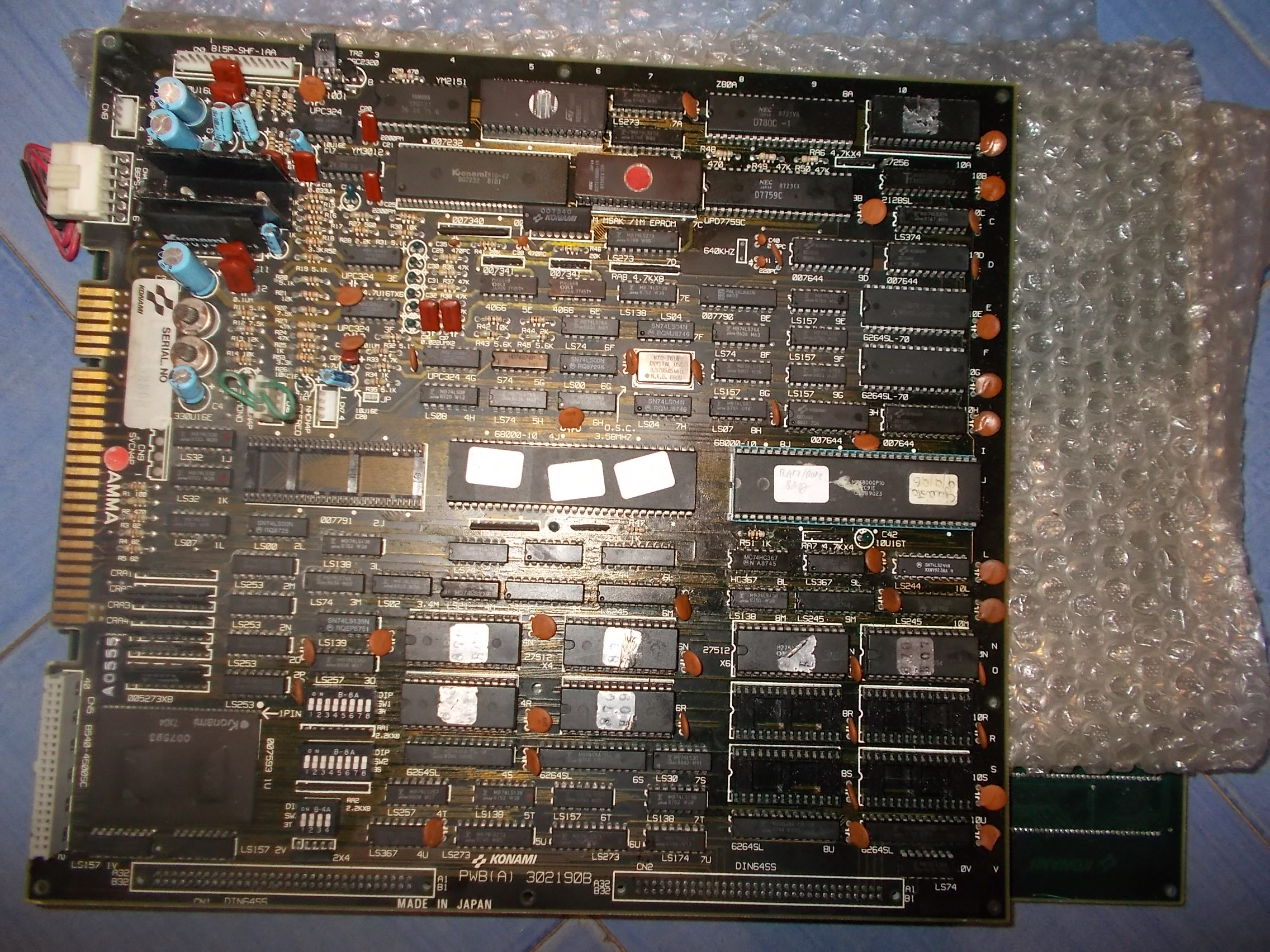
Board was the typical Konami pcb manufactured in Italy ( I believe Electronic Devices had a deal with them to import the pcbs and populate certain chips in Italy).
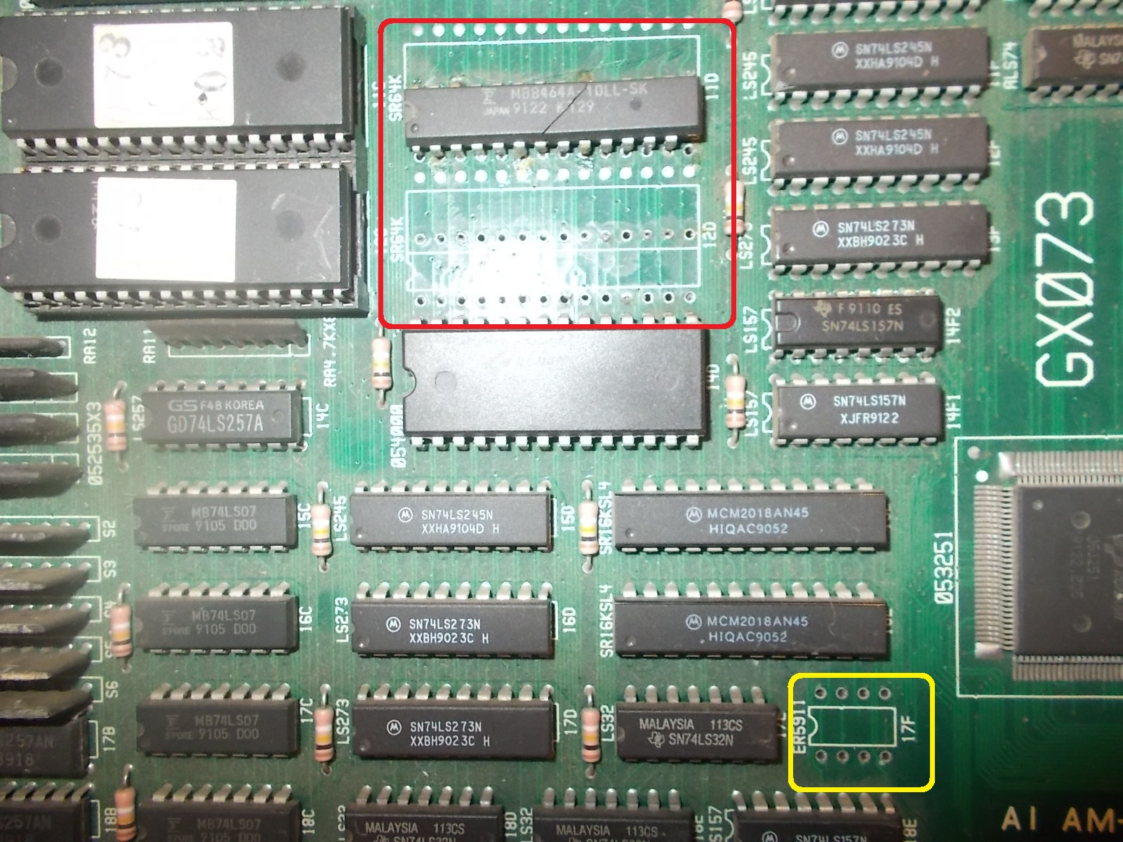
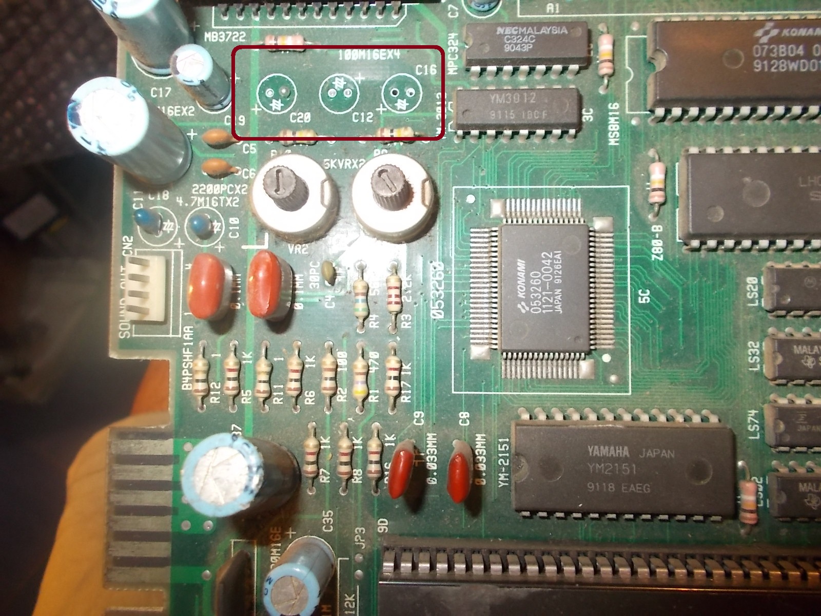
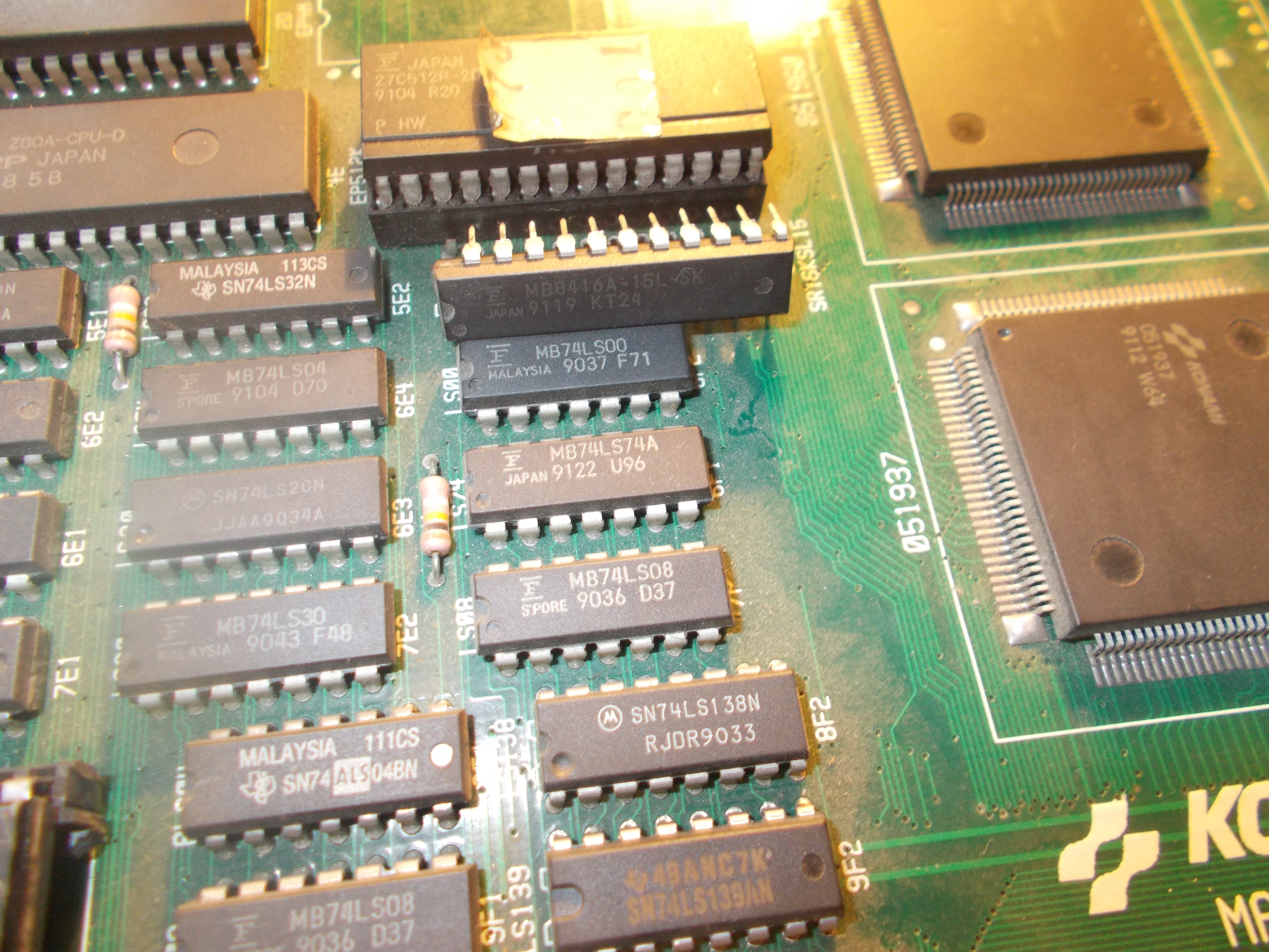
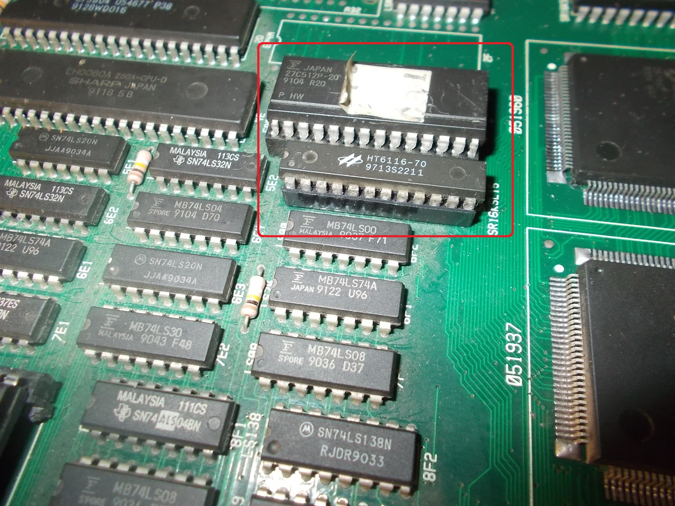
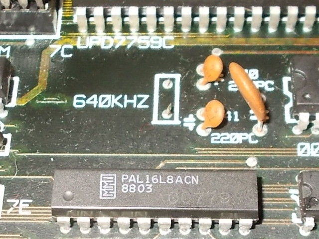
You regognize these boards because they have sound z80 made in Italy , soldered eproms and cheap sound potentiometer
Later on, beginning of 90s they started to put also general “E.Devices” stickers on eproms in place of Konami ones, but at least the eproms were socketed
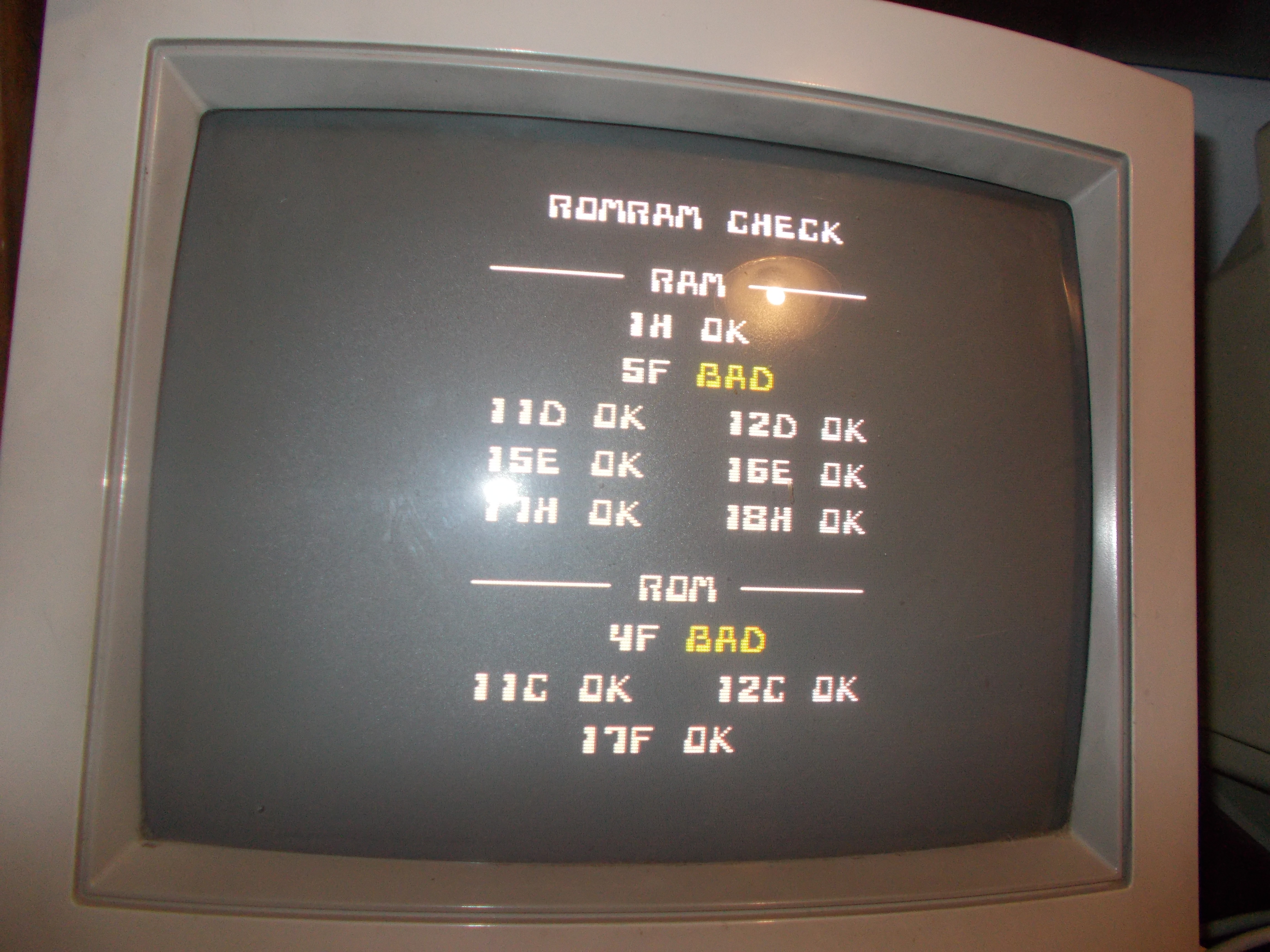
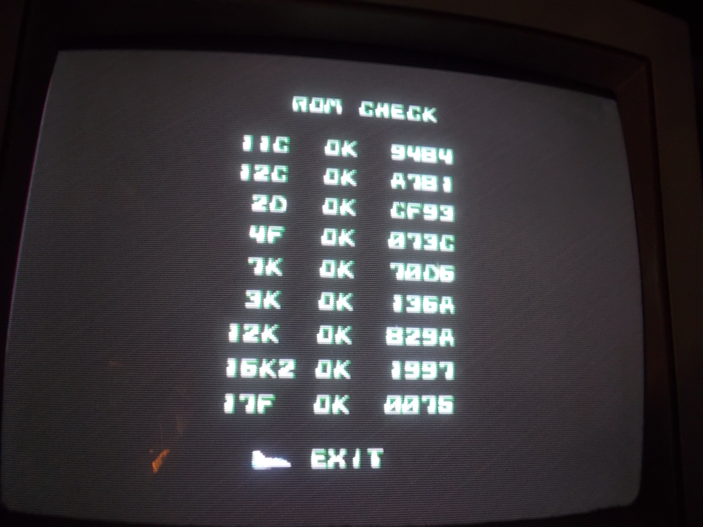
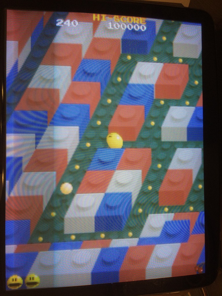
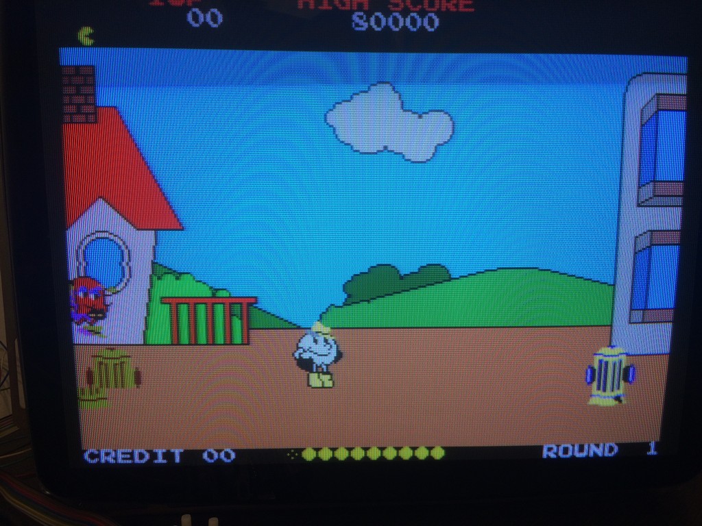
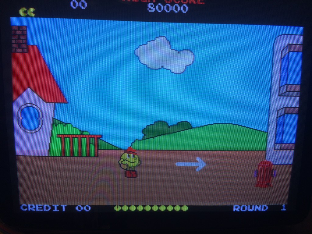
Back to this board, it booted and the graphic was OK but there was a continuous metallic sound all the time.
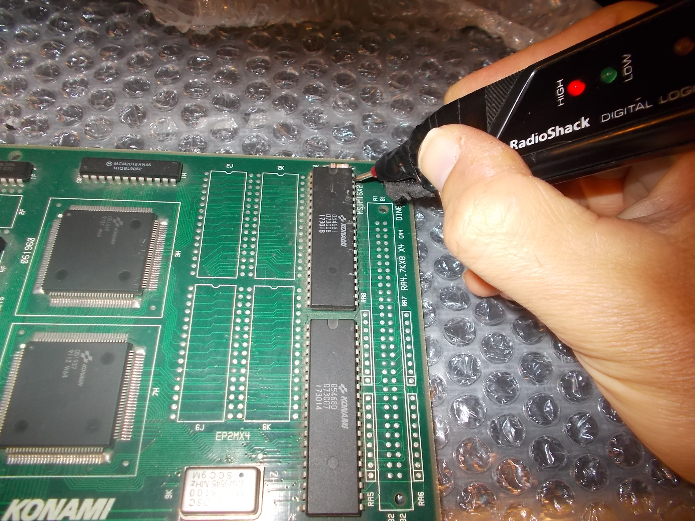
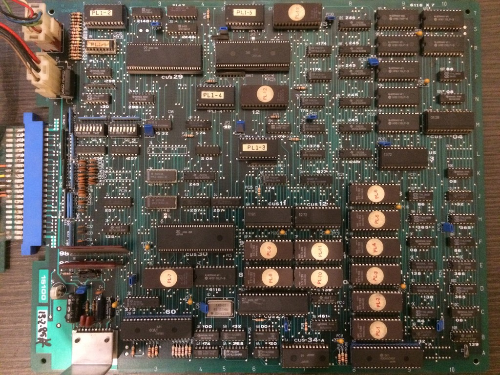
Ruled out DAC and OP AMPS because usually when these fails, you have at least either FM or samples working, I started to probe the sound circuit logic following the schematics.
I noticed that the commands from the main CPU were correctly sent to the sound section but as soon as the Z80 had an INTERRUPT request, the CPU didn’t aknowledge it and blocked itself
In particular:
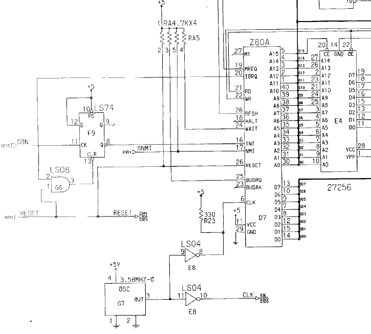
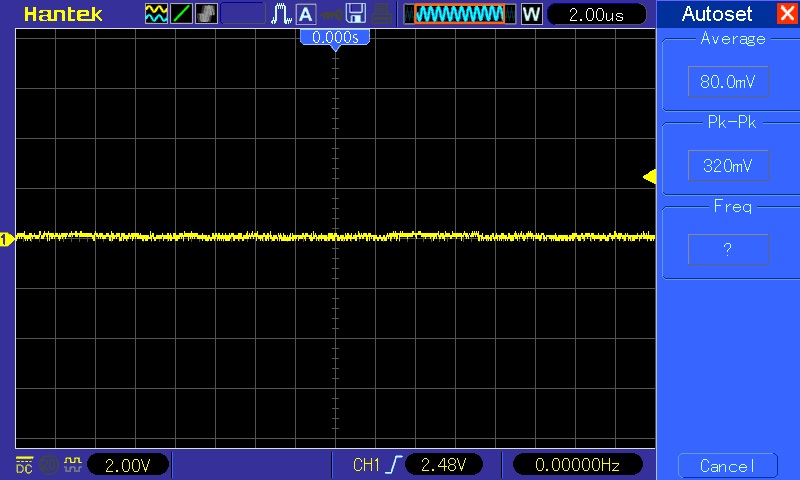
Signal IORQ didn’t go low, thus making the INT signal from the 74LS74 always LOW.
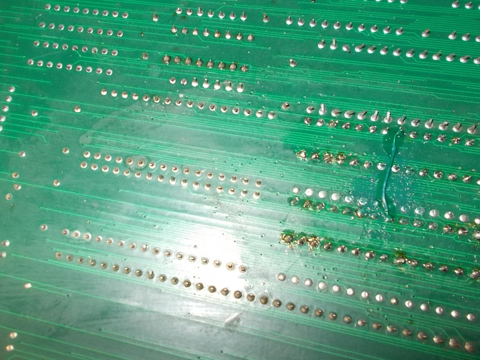
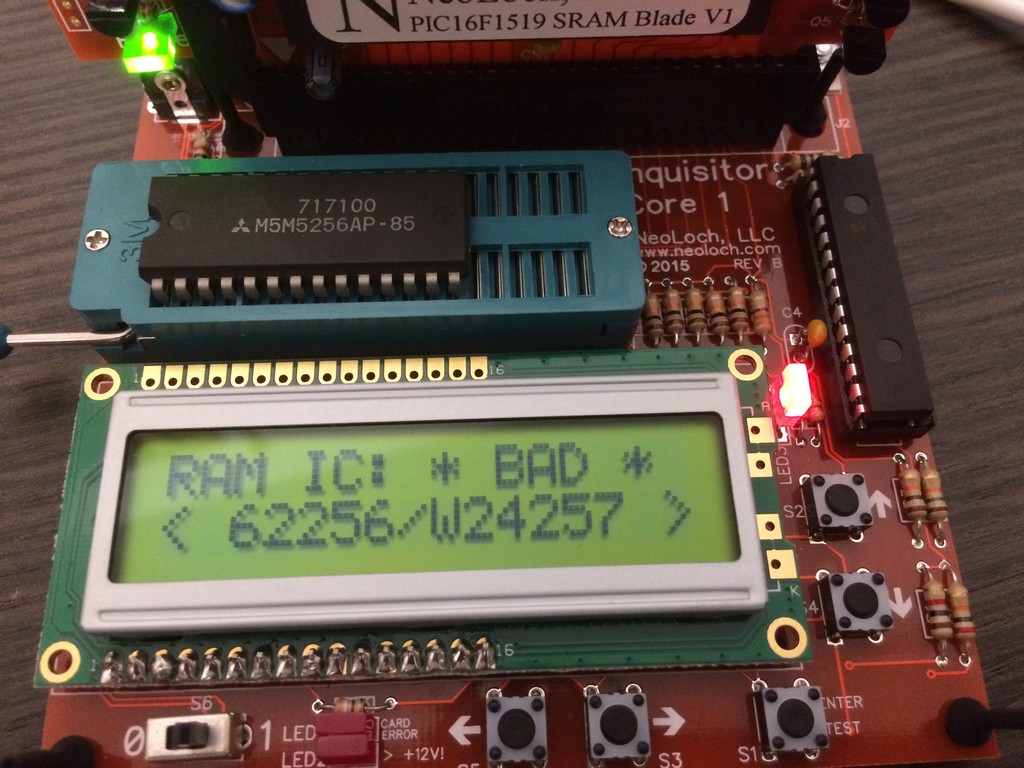
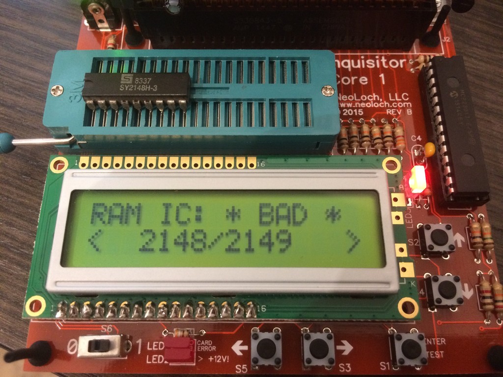
I proceeded to desolder the Z80 and tested it on another game with a socketed CPU and it confirmed to be bad.
While soldering the same Z80 by NEC used on proper Konami assembled boards, I also changed the sound potentiometer with an original Konami taken from another scrap game.
Game was fixed without any other issues.