PCB Repair LogsComments Off on Toaplan (Vimana – Out Zone) double repair log
Jul222018
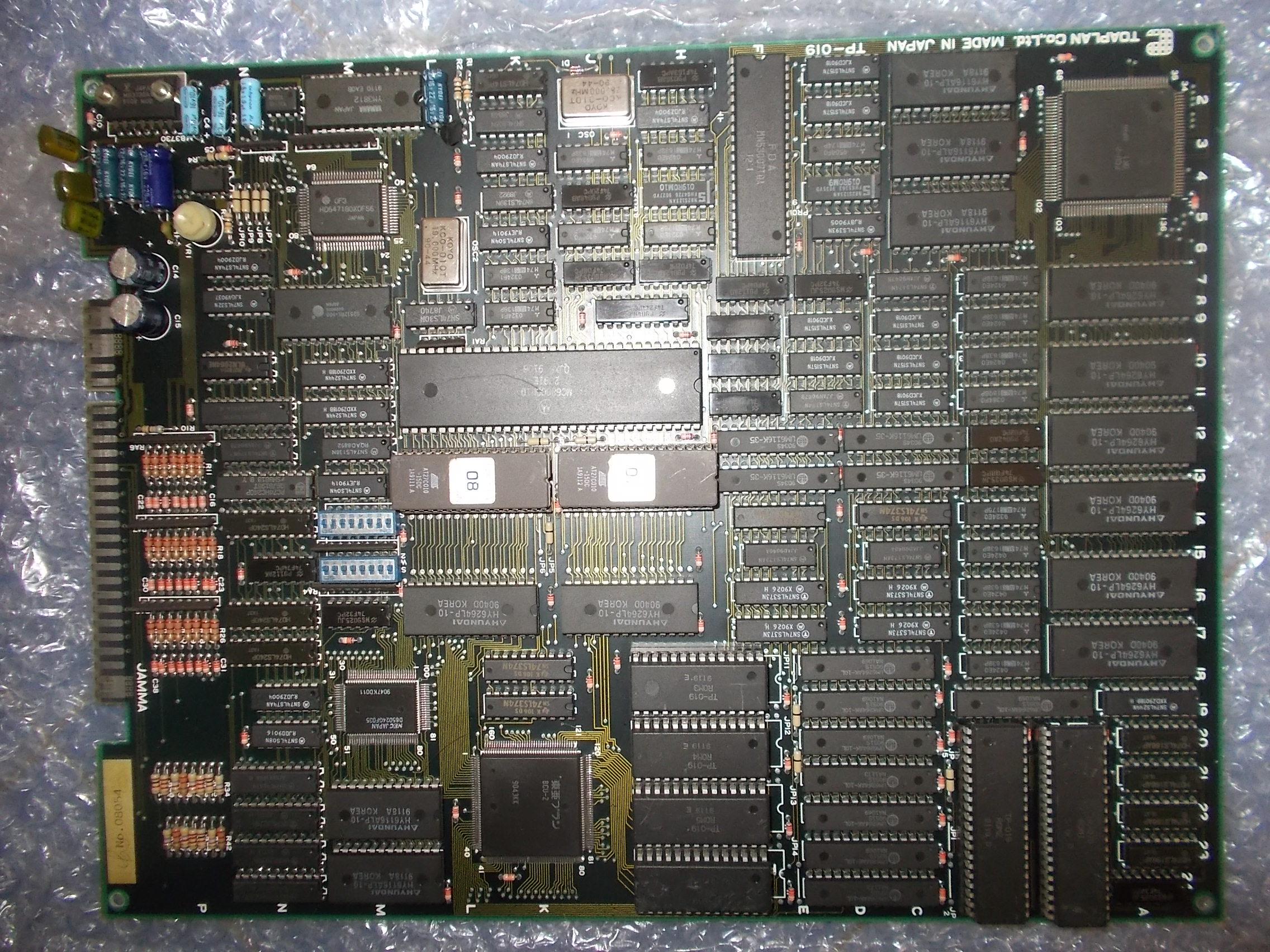
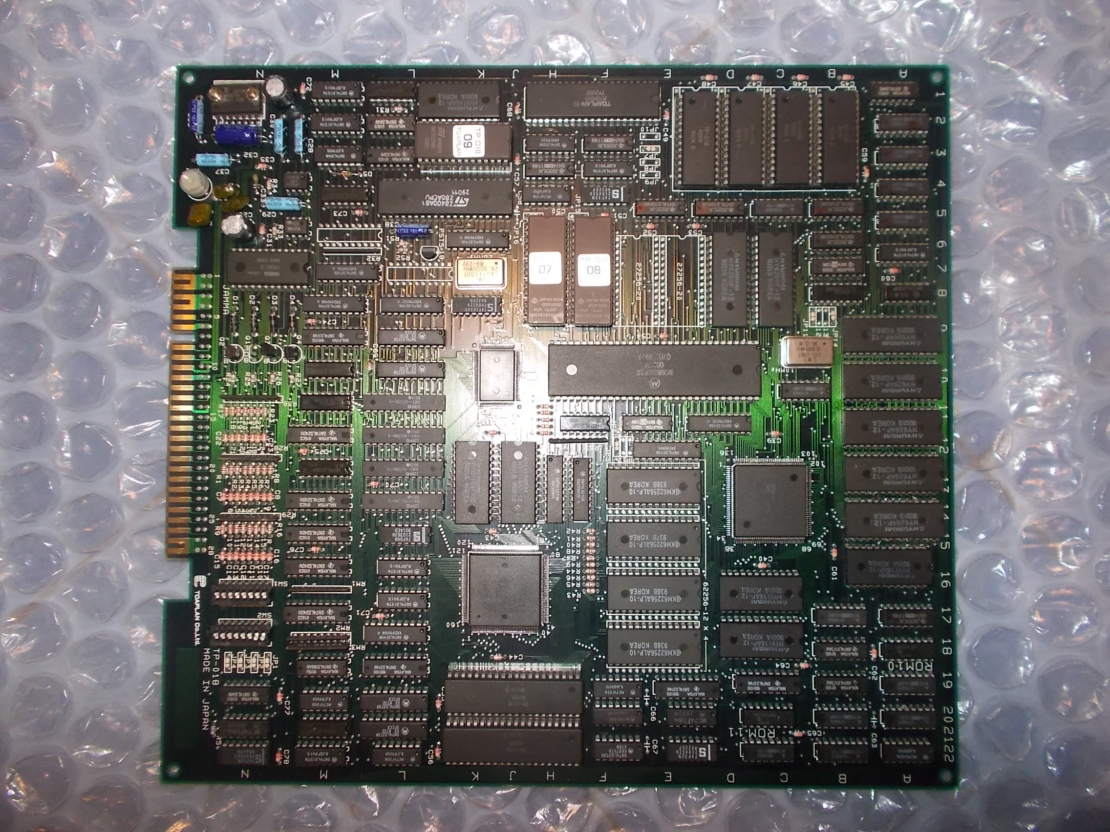
I’ve been sent from Portugal a box of faulty PCBs for repair with some Toaplan stuff inside like Vimana and Out Zone (both japanese revision)
Vimana :
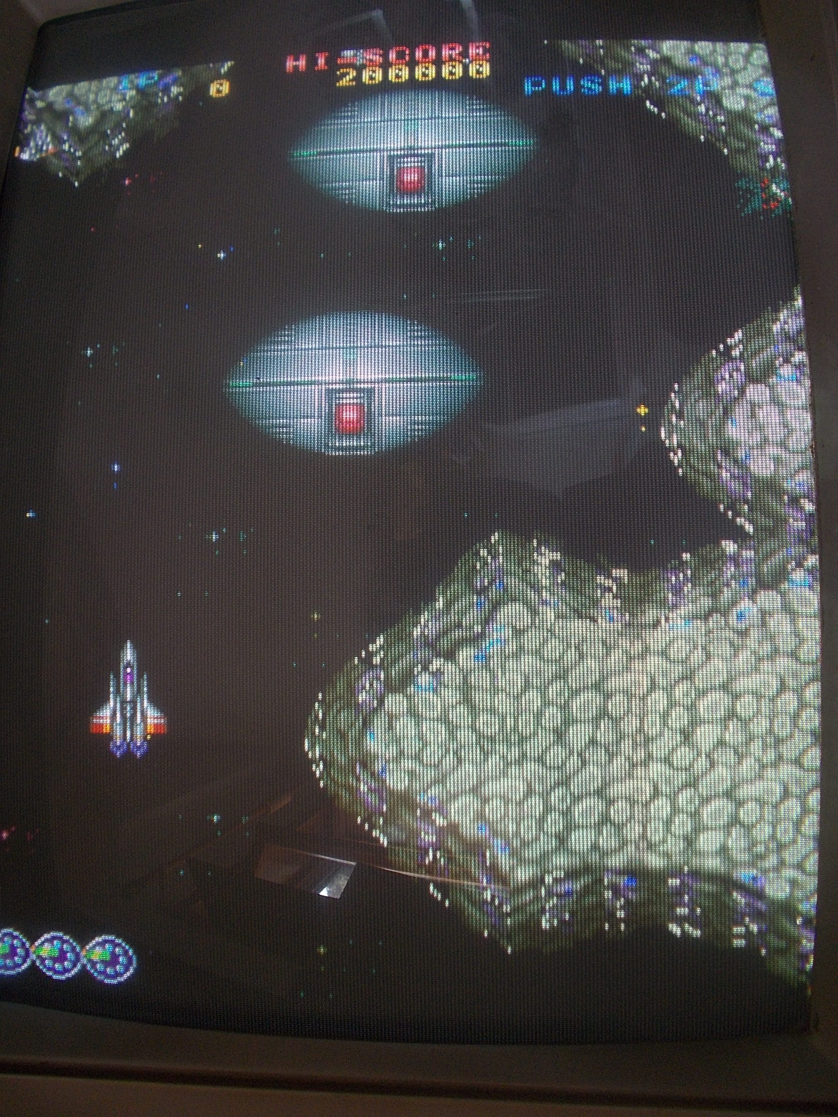
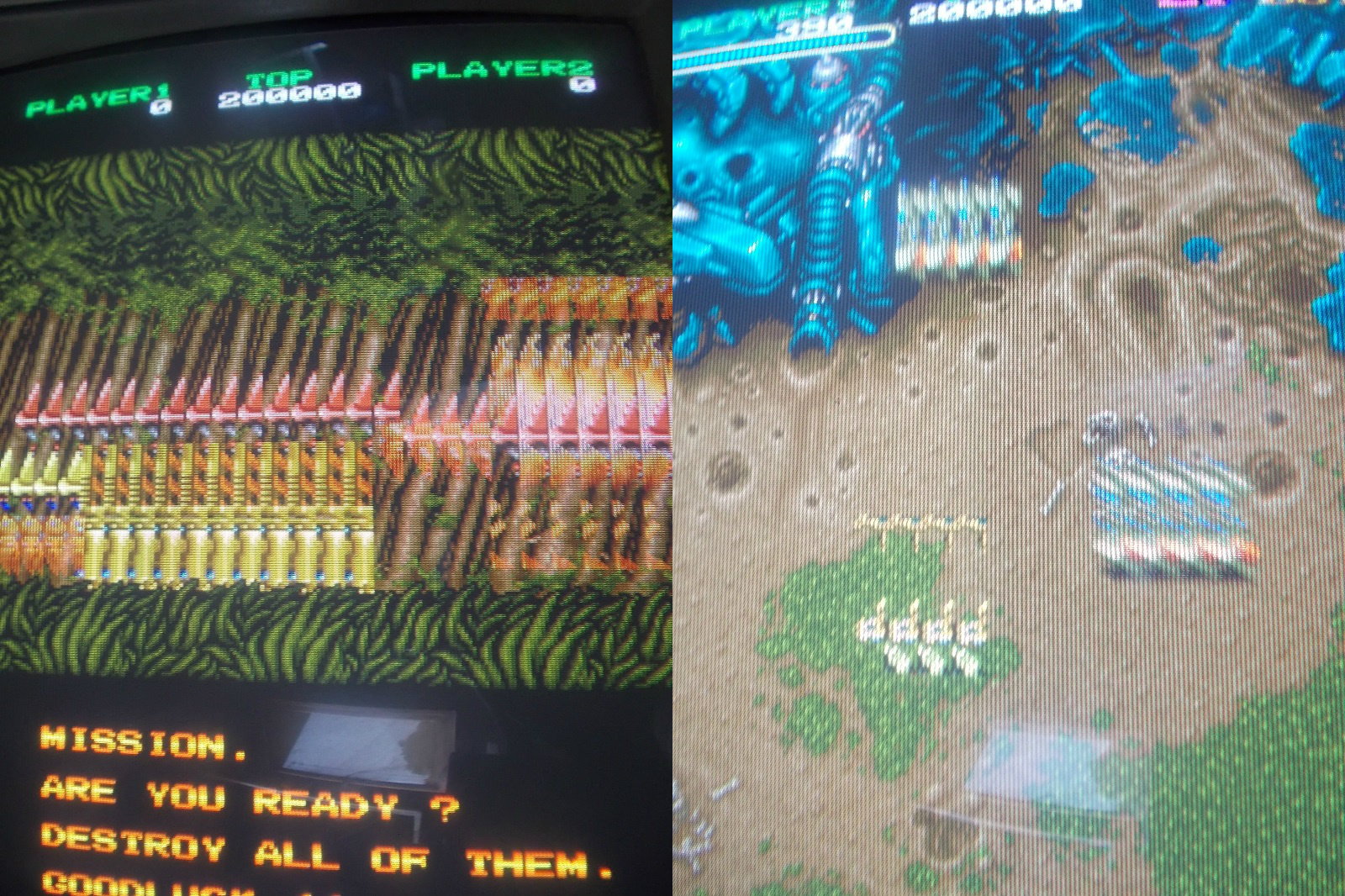
Board was booting and played fine except for some little glitches on background:
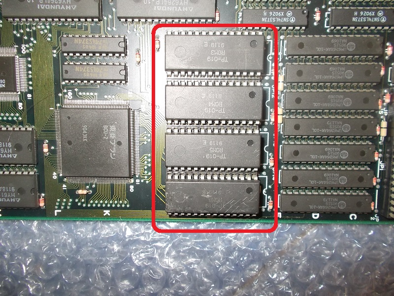
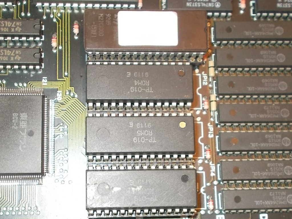
Backgrounds data are stored in four 28 pin 1Mbit MASK ROMs:
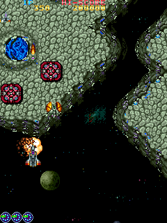
Devices were dumped fine except the one @ROM3 which gave inconsistent readings.Loading the file into MAME emulator reproduced the issue exactly:
I replaced the faulty MASK rom with a 32 pin 1Mbit non-JEDEC EPROM (adding the missing sockets)
Board 100% fixed:
Out Zone :
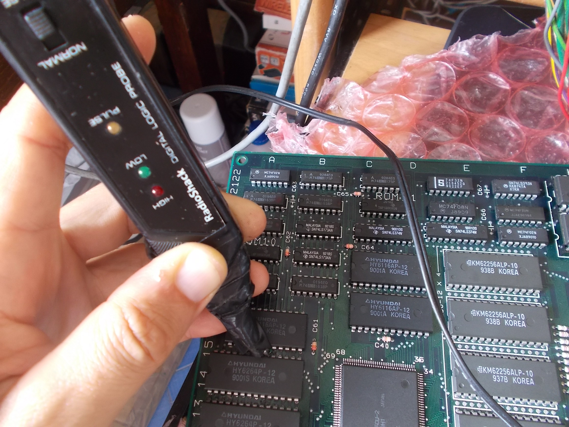
Board booted but sprites were garbled :
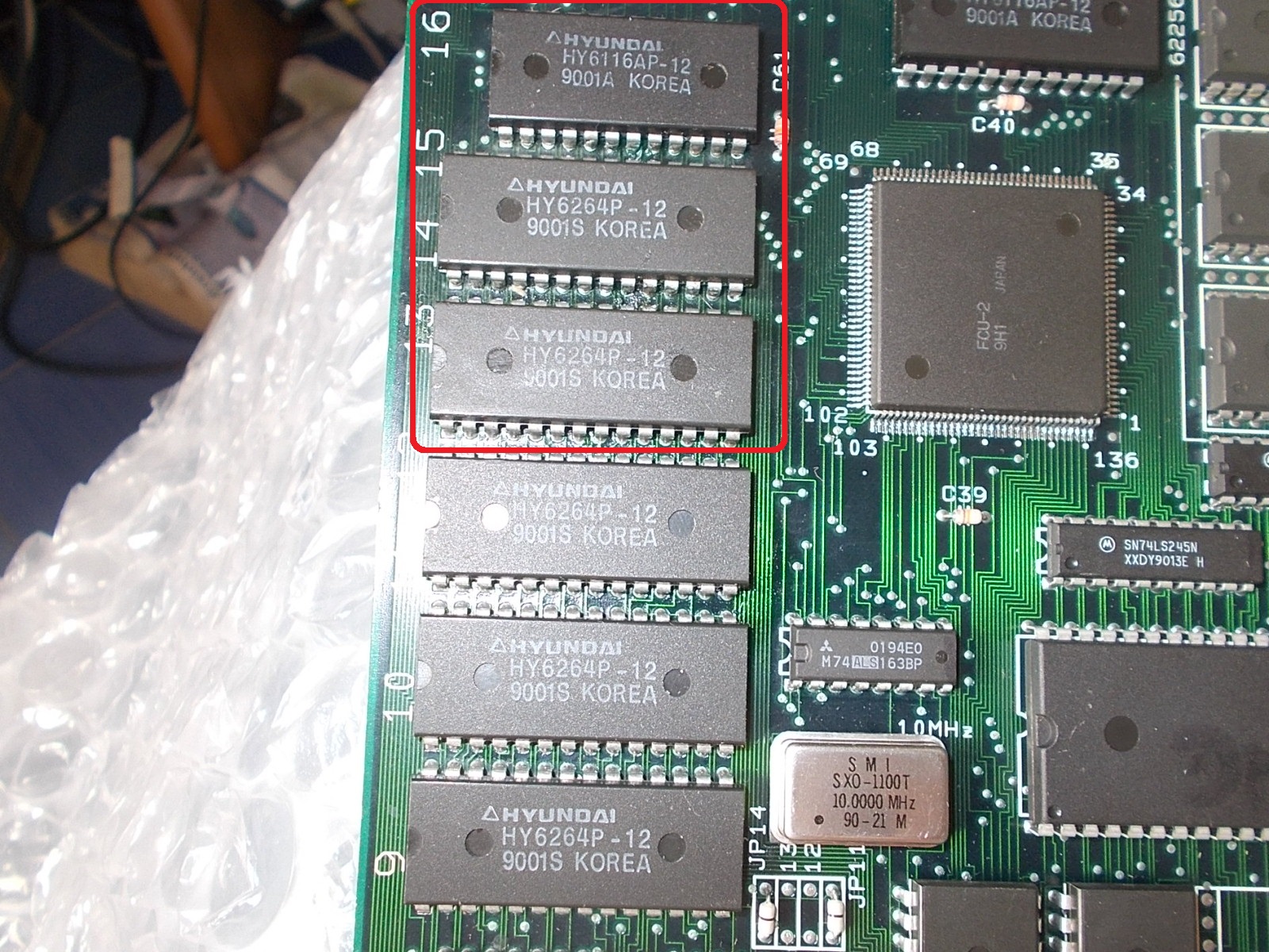
Probing a row of RAMs revealed /CE pins on three of them (the two 6264 @13A-14A and the 6116 @16A) were receiving no signals :
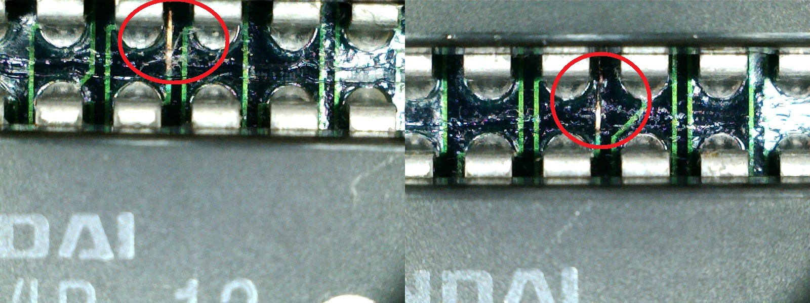
At a closer inspection I found a burnt trace going under them:
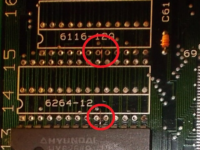
I removed two of the three involved RAMs:
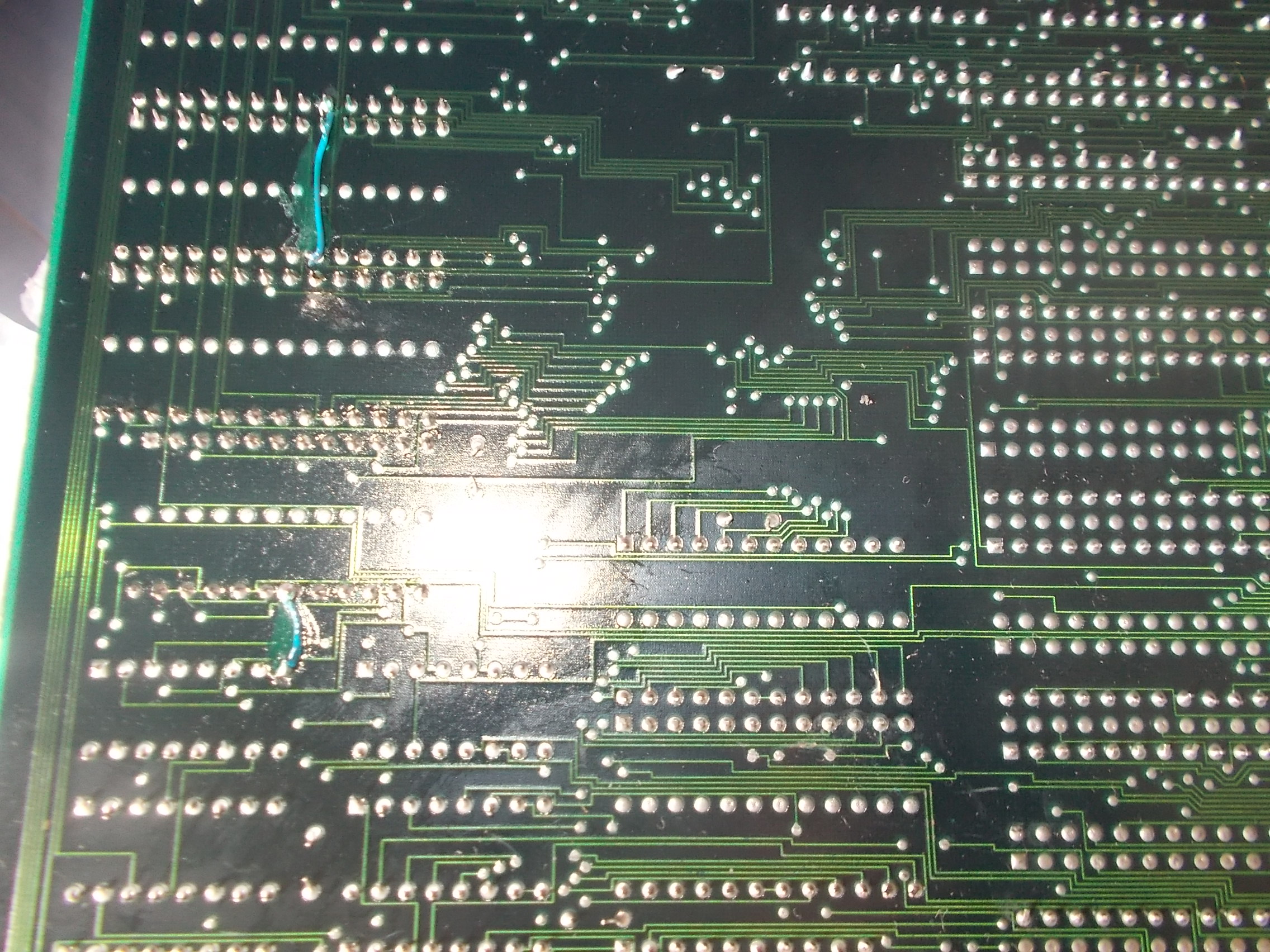
Tracing back the burnt trace I figured out it was a GROUND signal that should have been daisy-chained to the /CE lines (grounding also address lines A10-A9-A8 of the 6116) of the three RAMs enabling the chips.A couple of jumper wires did the job:
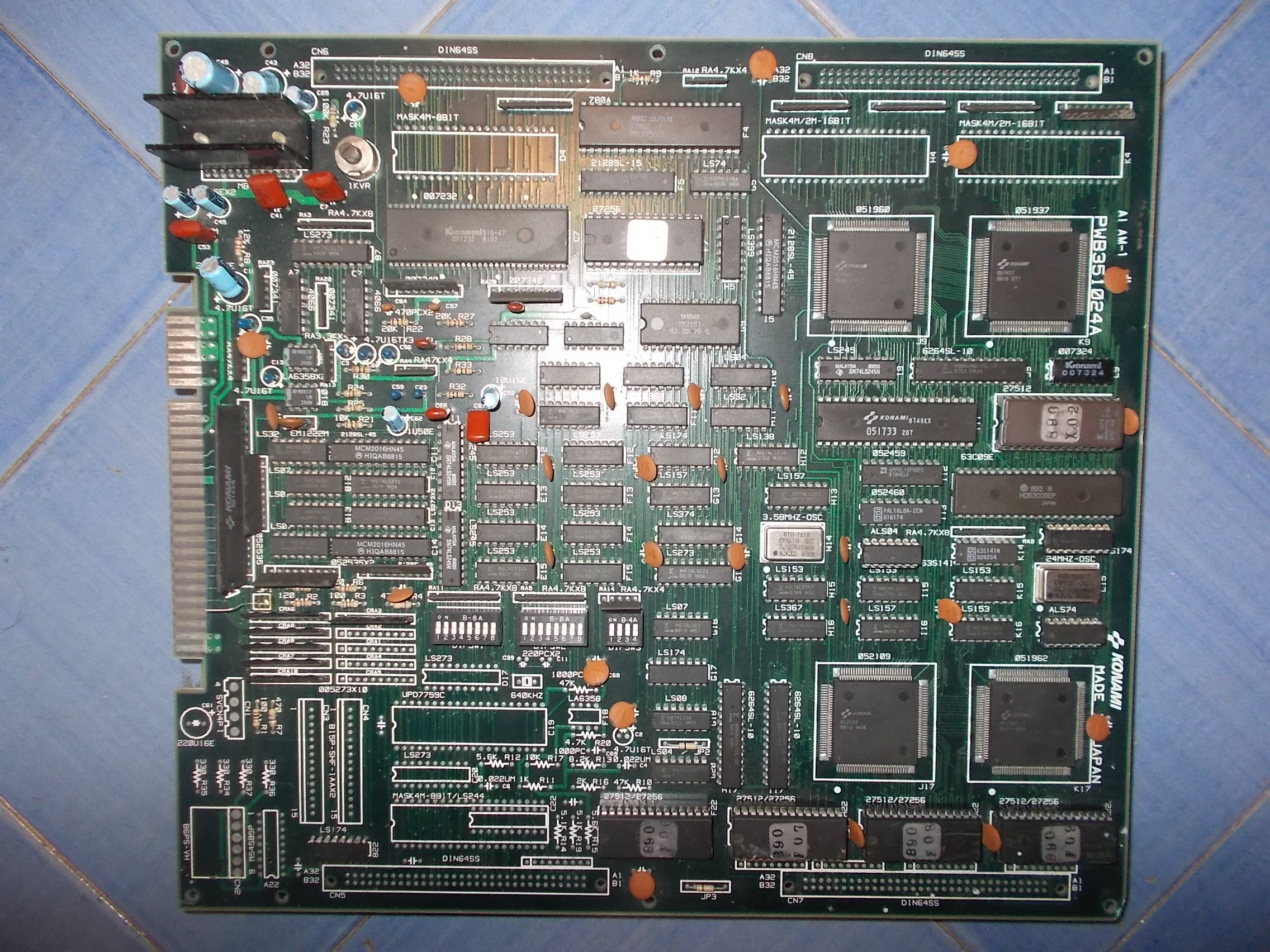
Received from Austria this Devastators PCB (manufactured by Konami in the distant 1988)
The board was constantly watchdogging sign that no valid code was executed :
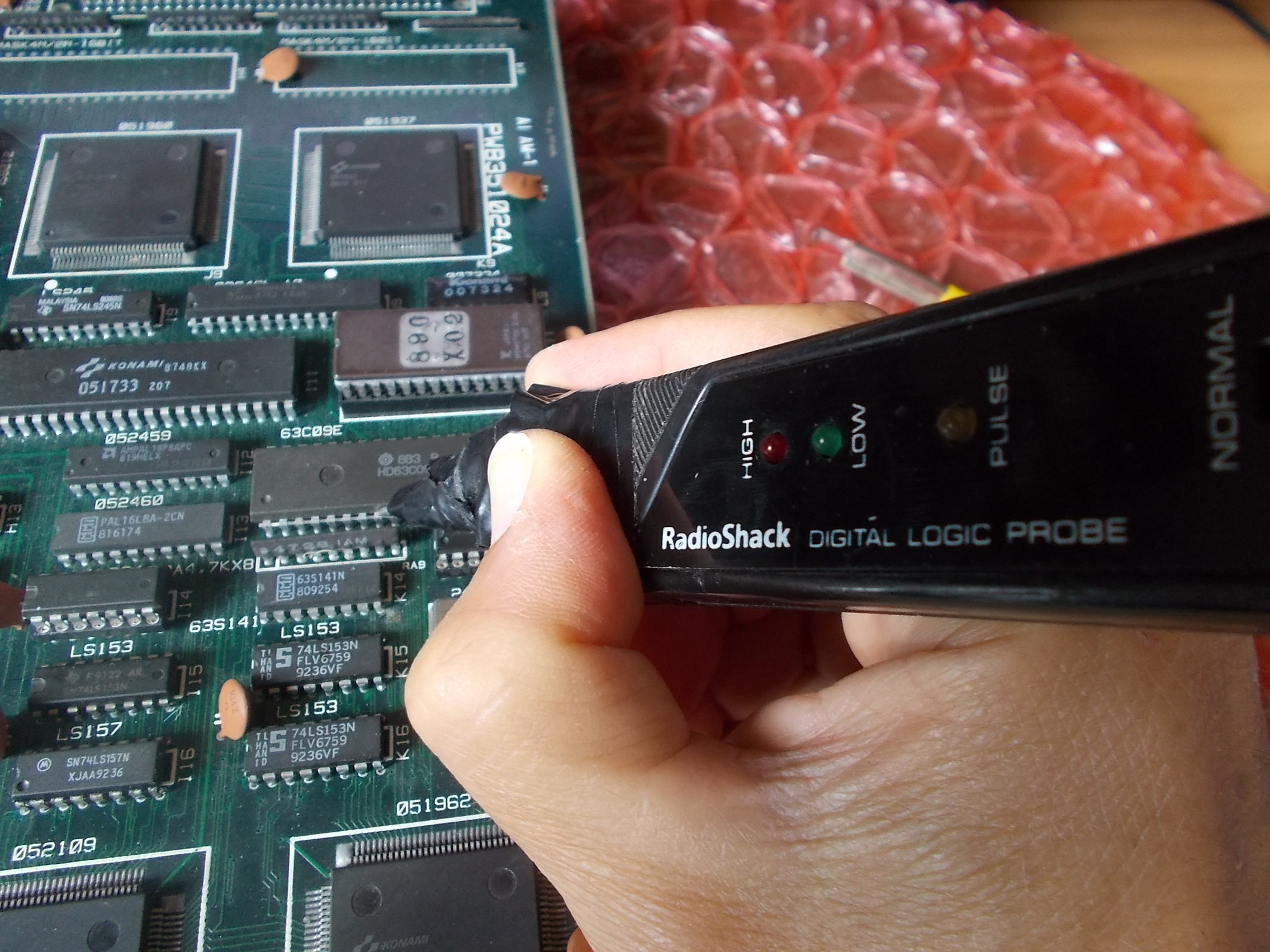
Probing the HD63C09E main CPU revelead some address lines were dead:
I removed it :
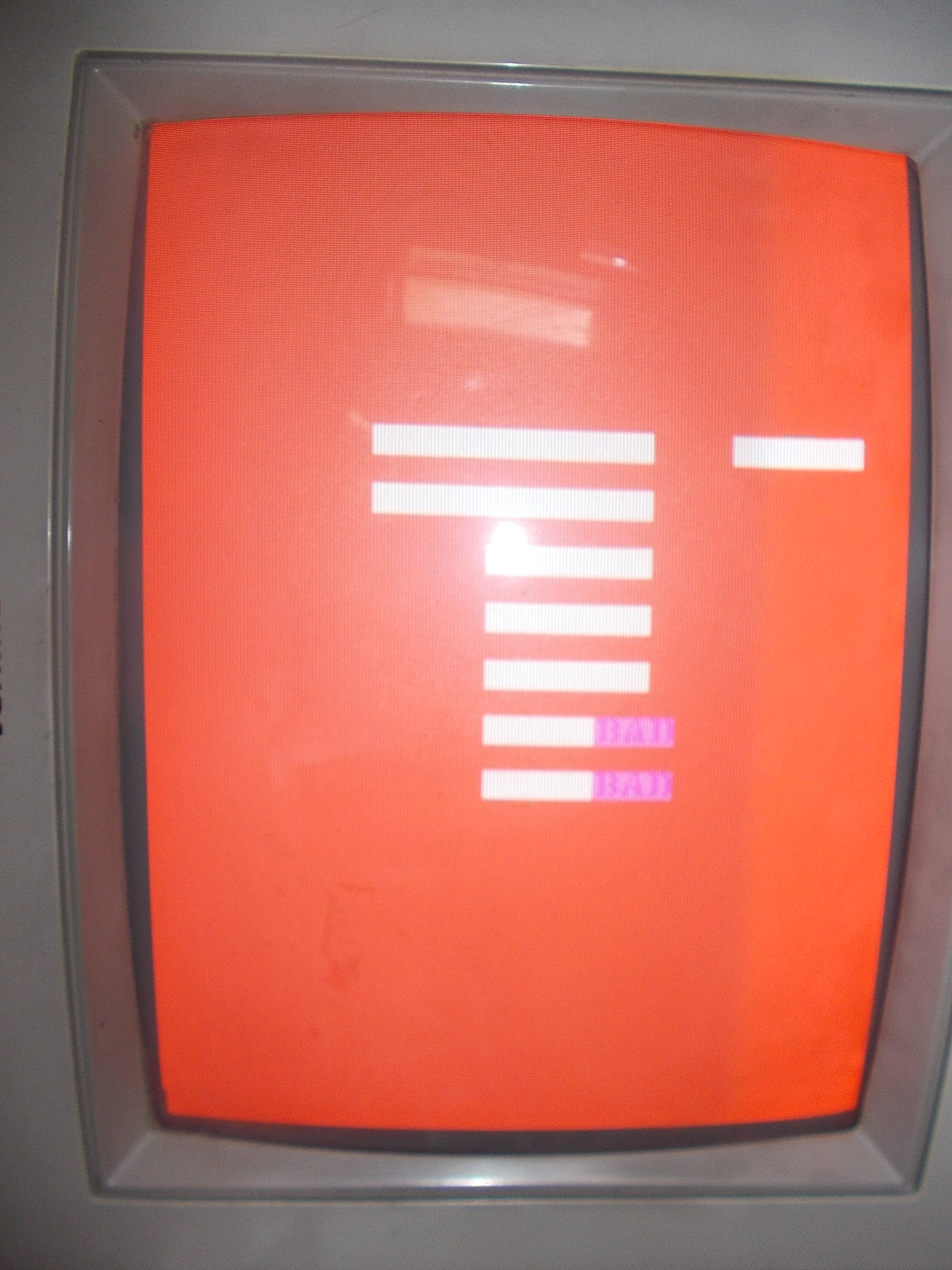
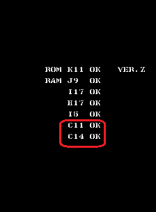
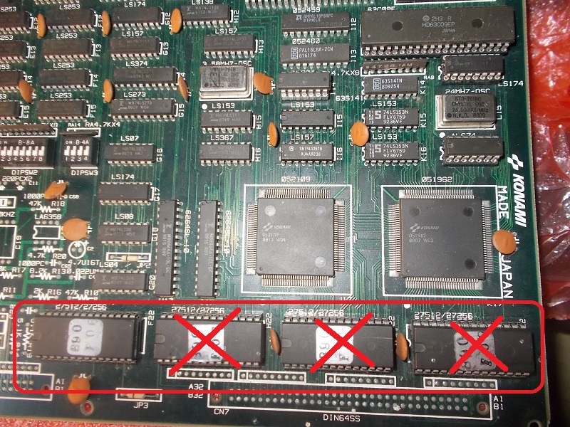
Trying the CPU in another board confirmed it was really bad so I replaced it.The board booted up but it was failing the POST showing two bad devices which at fist glance I could not recognize due the complete lack of graphics :
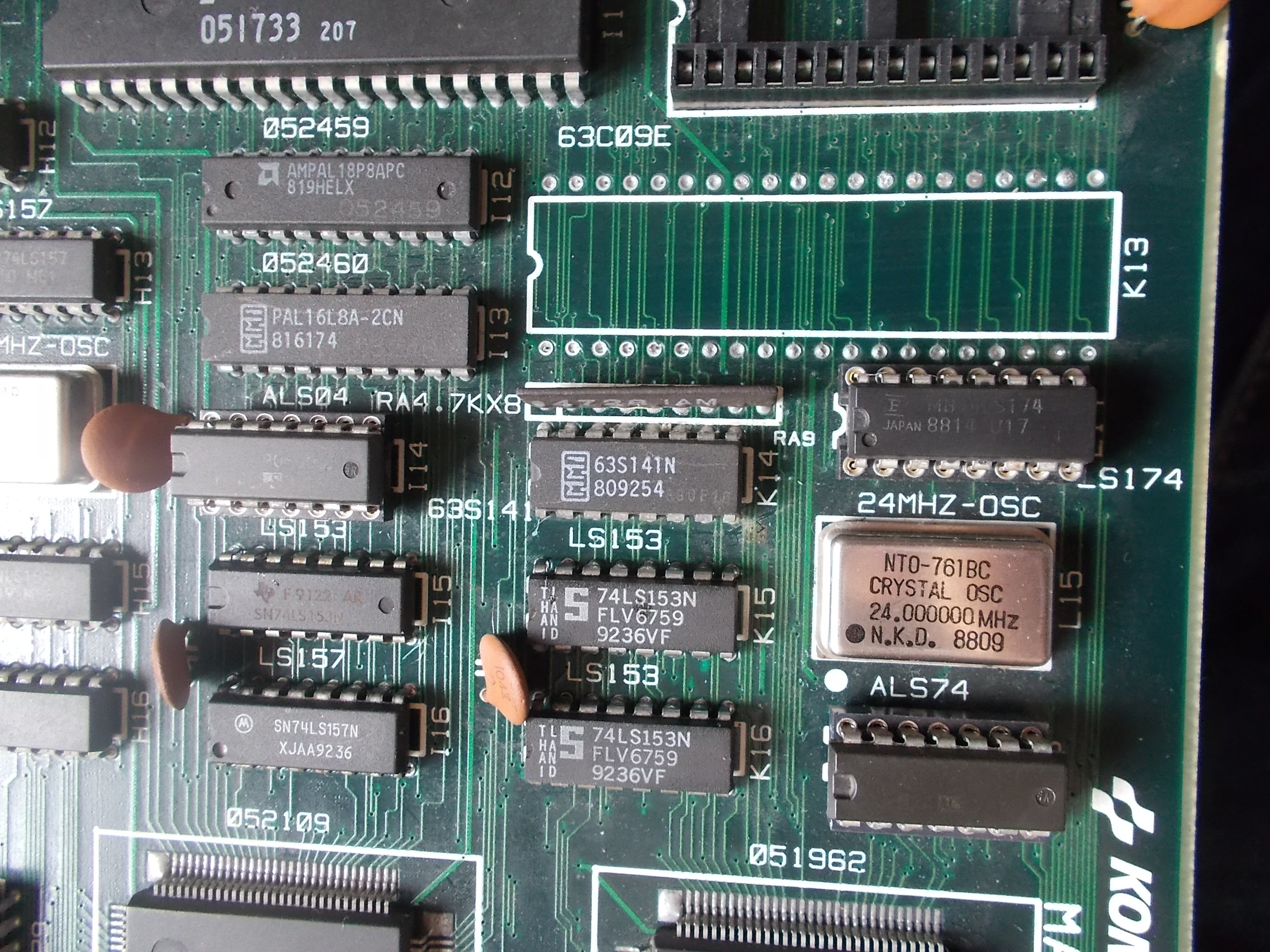
Thanks to MAME I figured out they were the ones @C11 and C14 :
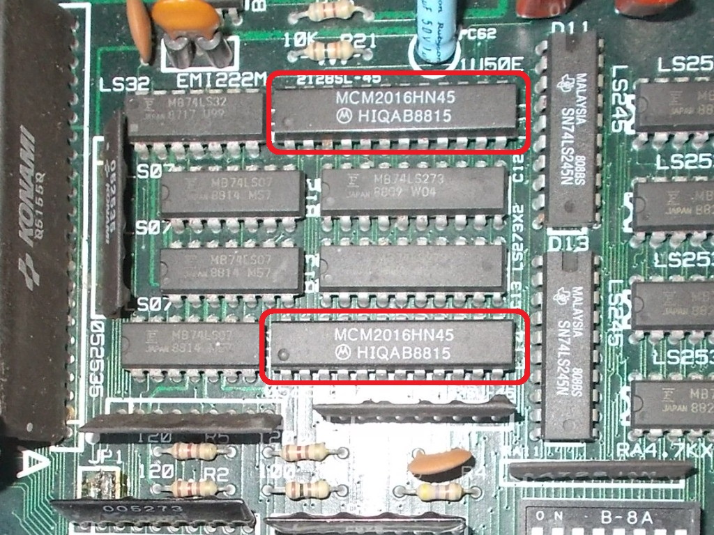
On PCB they are the two 2k x 8-bit static RAMs (Motorola MCM2016 used) which are part of the palette colors circuit
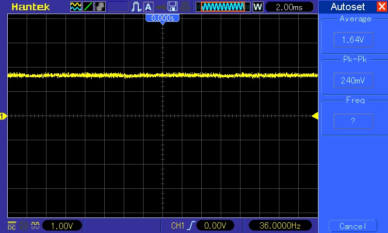
Probing the one @C14 revealed stuck data signals:
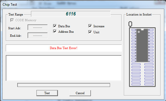
RAM chip failed the out-of-circuit testing:
Now the board booted into game but with severe graphics issue : the backgrounds had wrong colors and sprites were missing.Sound was absent too:
I dumped the four OTP MASK ROMs that store tiles data and found three bad ones :
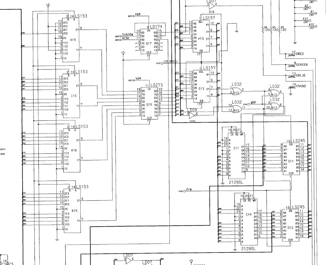
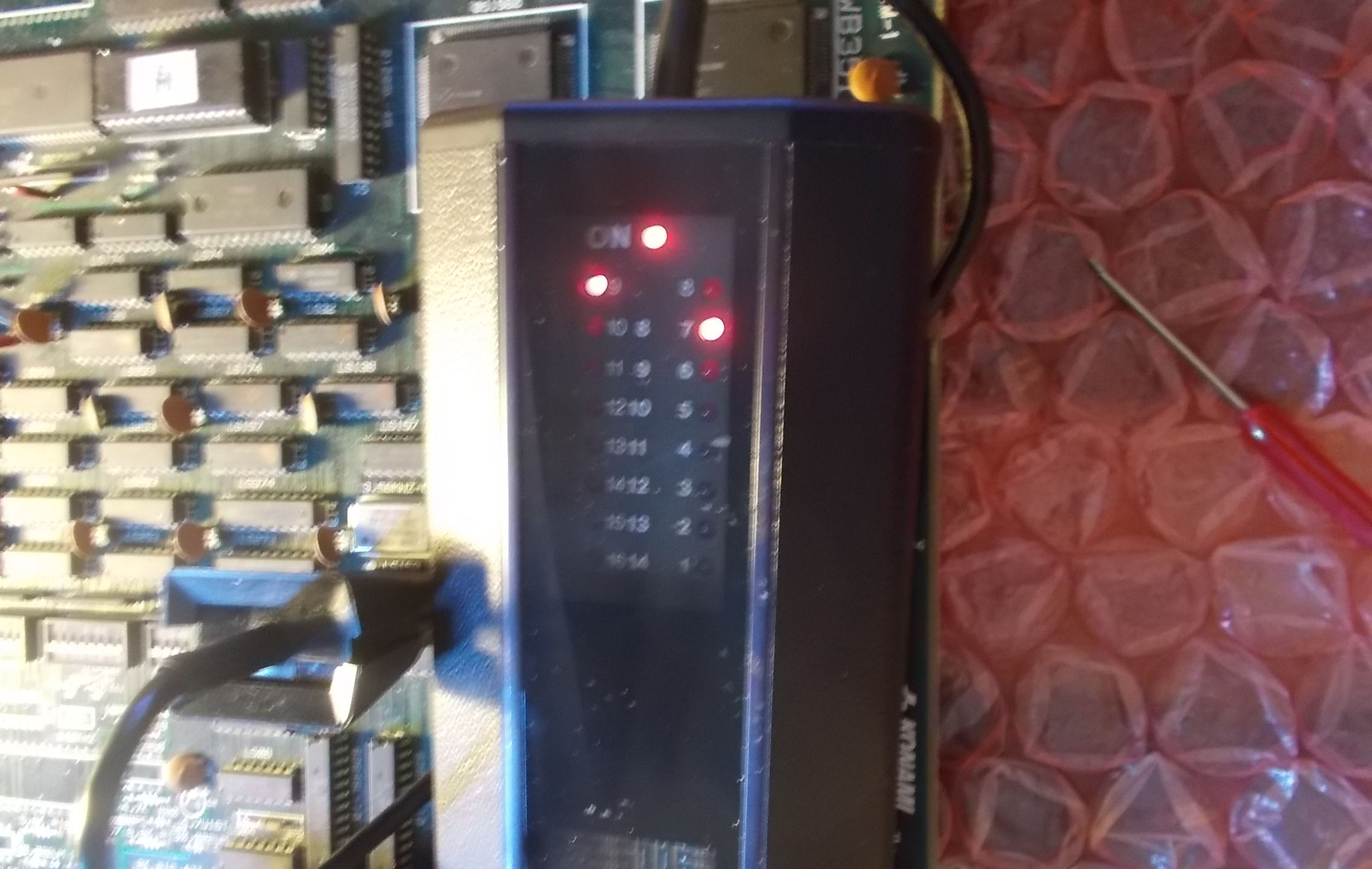
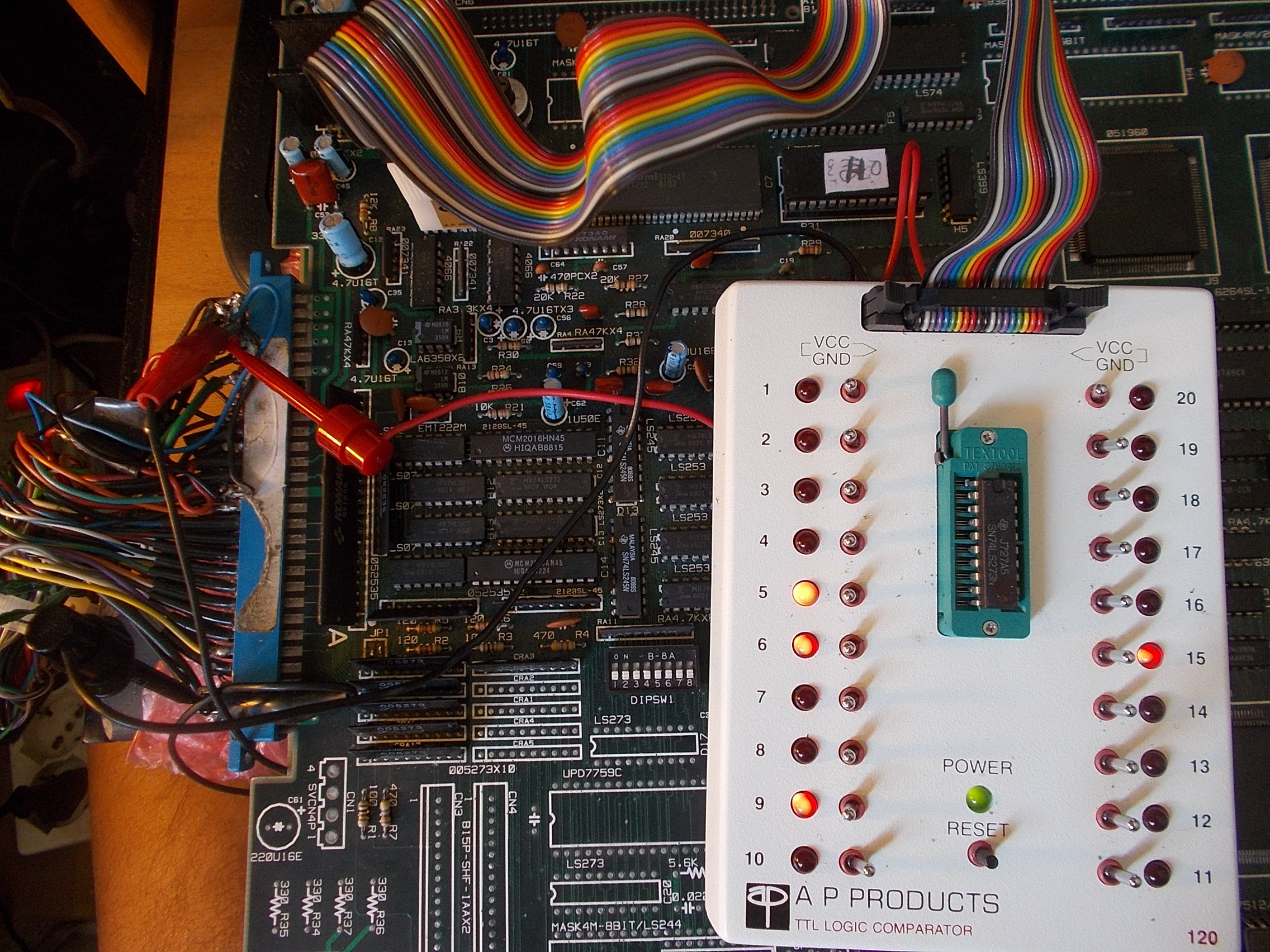
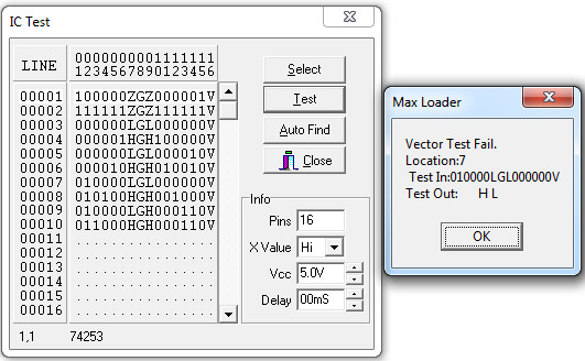
But this made no real improvements.Board is almost fully populated with Fuitsu TTLs so I went to test them in-circuit with a logic comparator starting from this part of circuit which is involved in color generation :
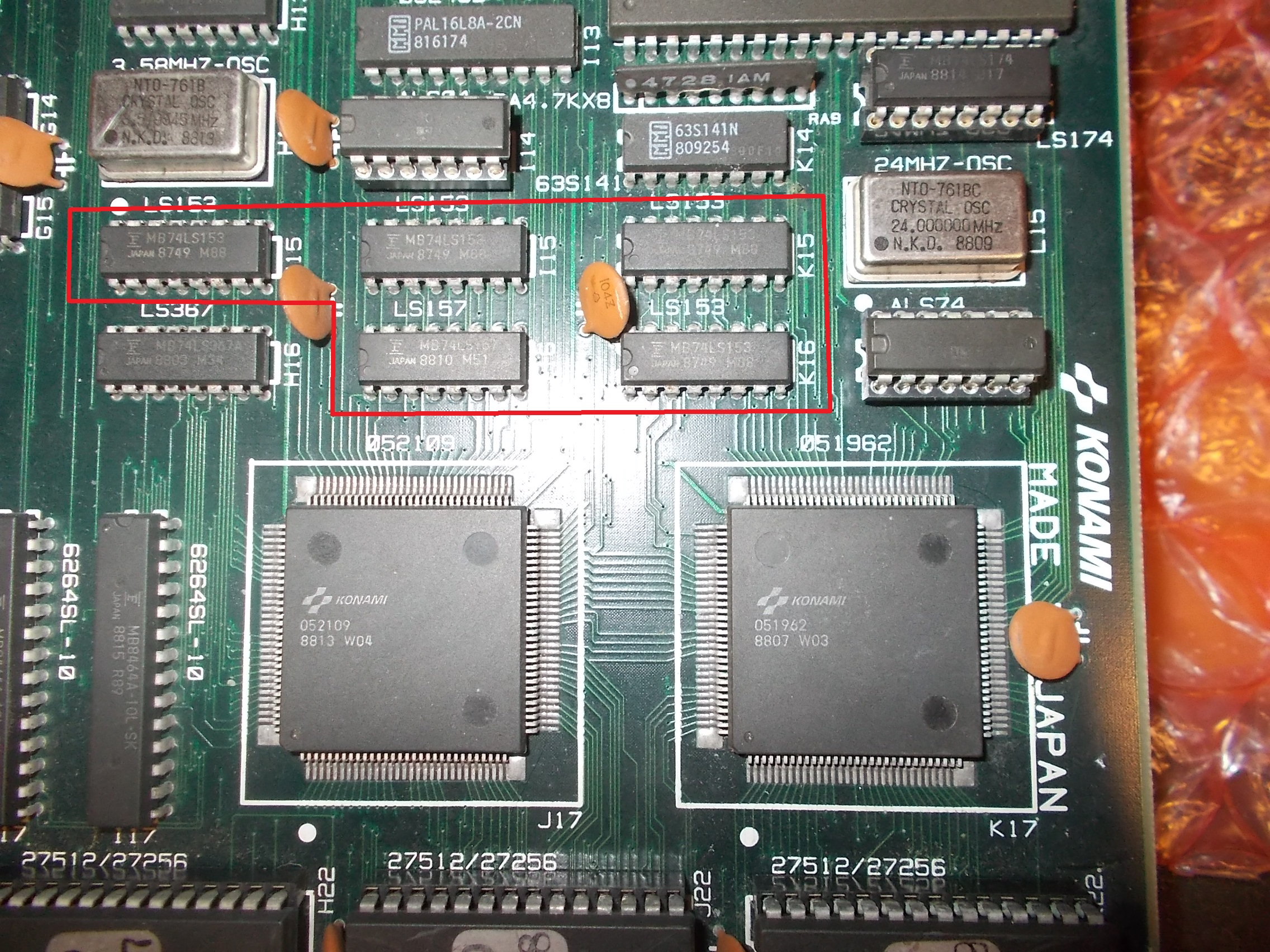
I found five bad mutiplexers with floating outputs:
This restored correct backgrounds:
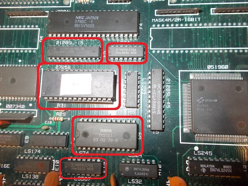
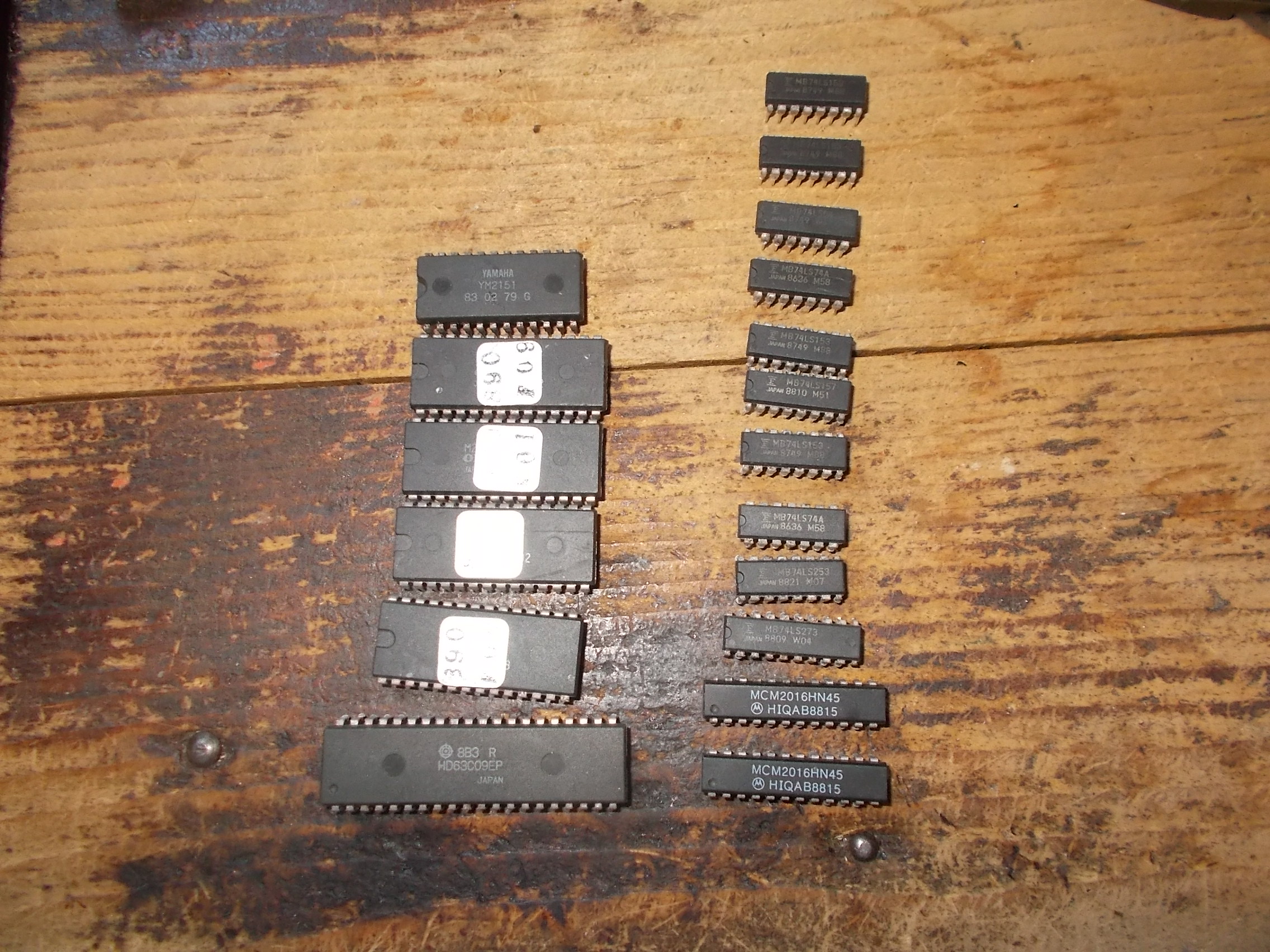
I decided to troubleshoot for first the lack of sound.Found in rapid succession these bad ICs:
YM2151 (with serial data output pin stuck high)
sound RAM and ROM
two 74LS74 @G5-F10
And a 74LS273 @B7 with some floating outputs:
Sound was back :
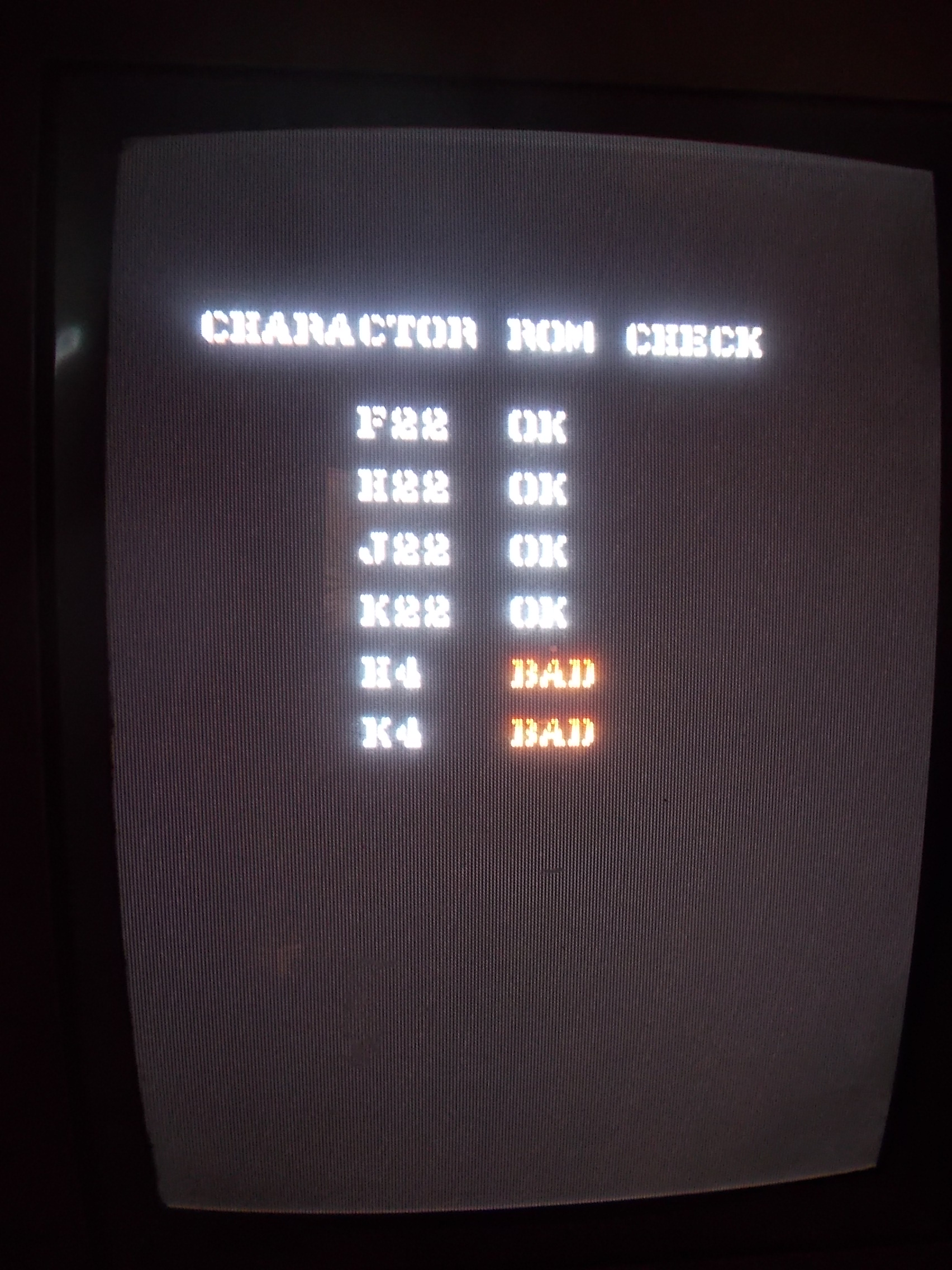
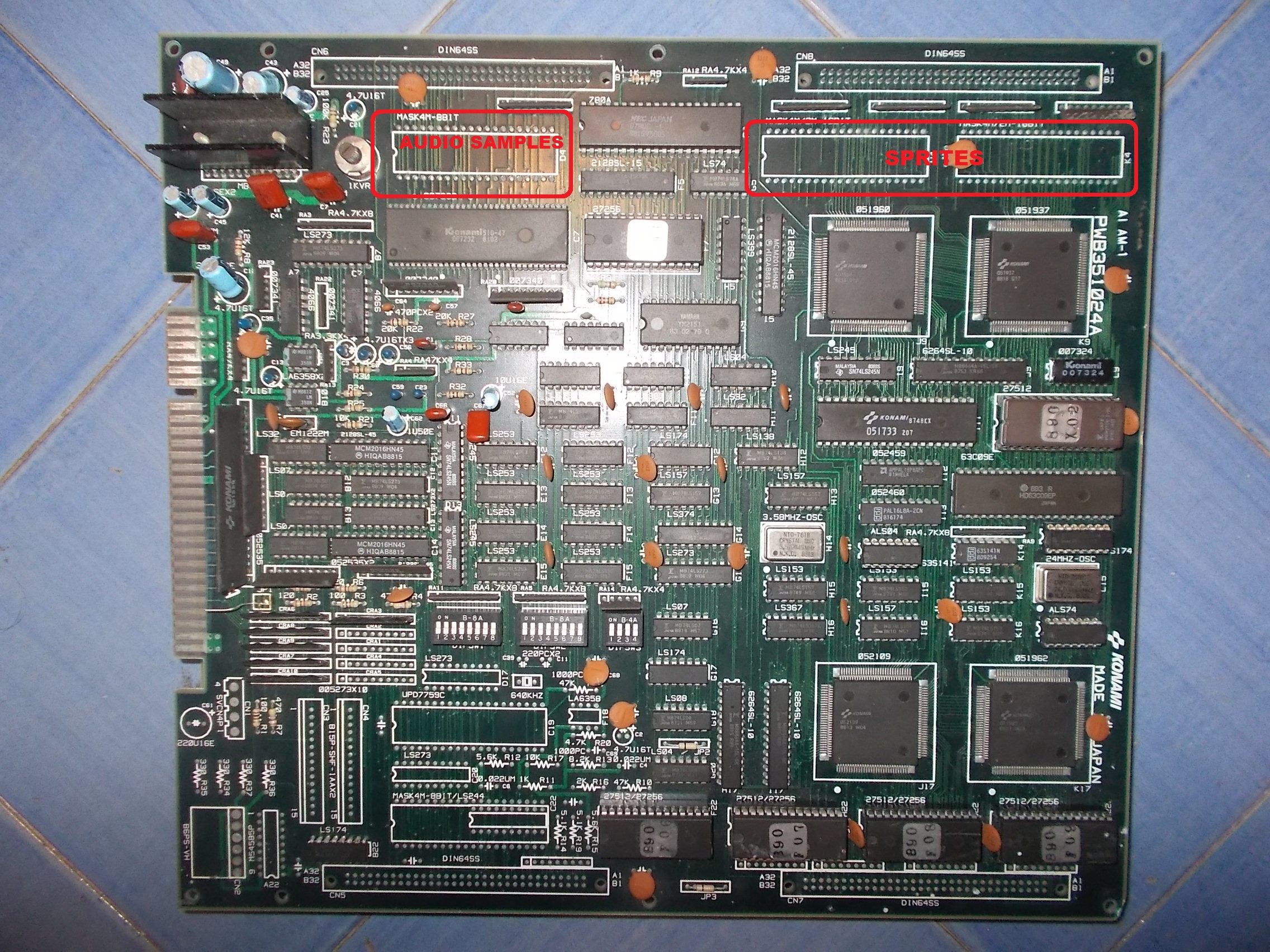
Now the lack of sprites.MASK ROMs check reported two bad devices @H4-K4 which are the ones storing sprites data:
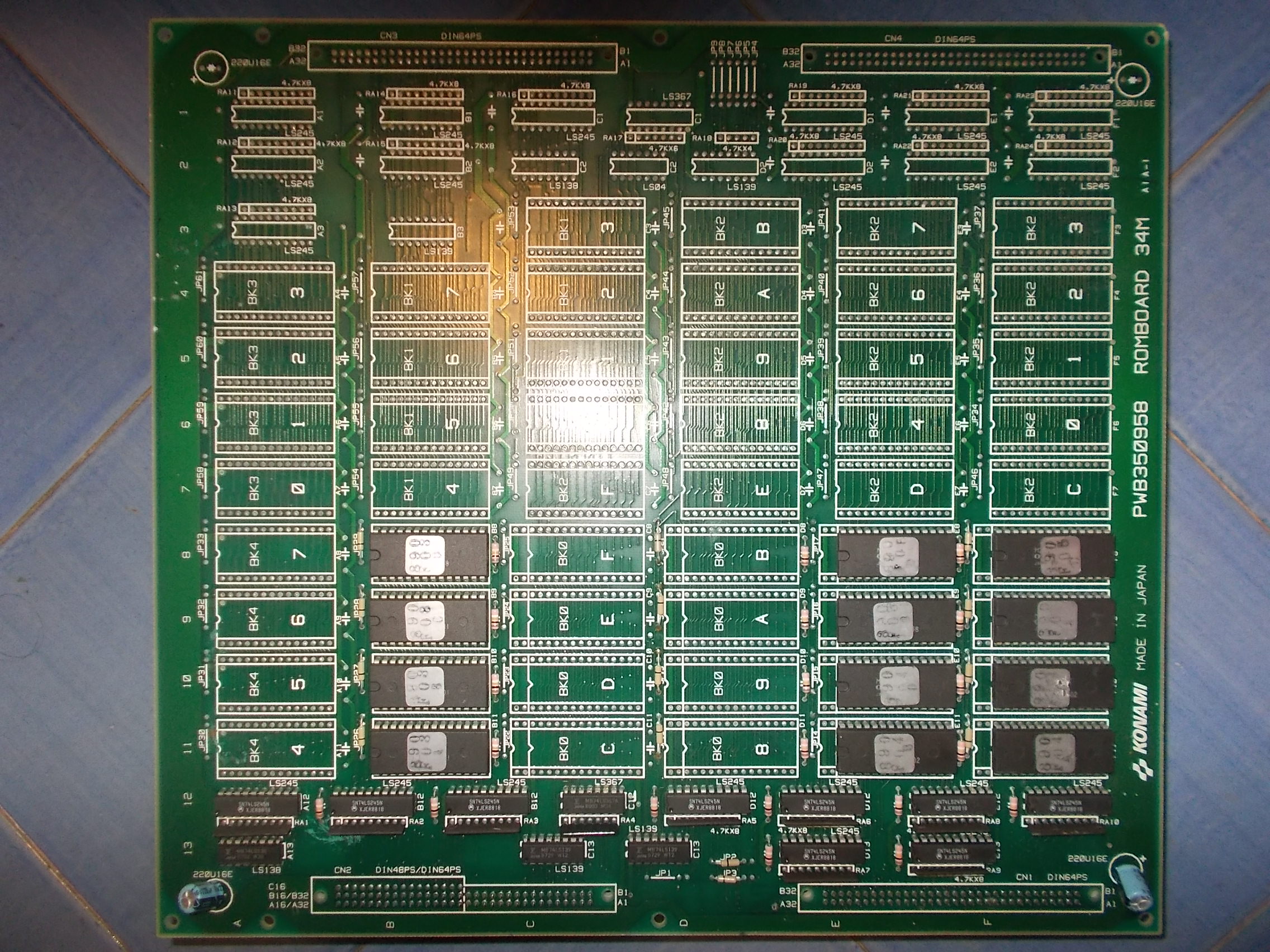
This particular PCB uses a bottom ROM board with sprites and audio samples ROMs :
But the top board can also host three 4Mbit devices for the same data so you can get rid of the ROM board :
This is what I opted instead of troubleshooting it since all the splitted ROMs were soldered in.I programmed three 27C400 EPROMs with MAME dumps:
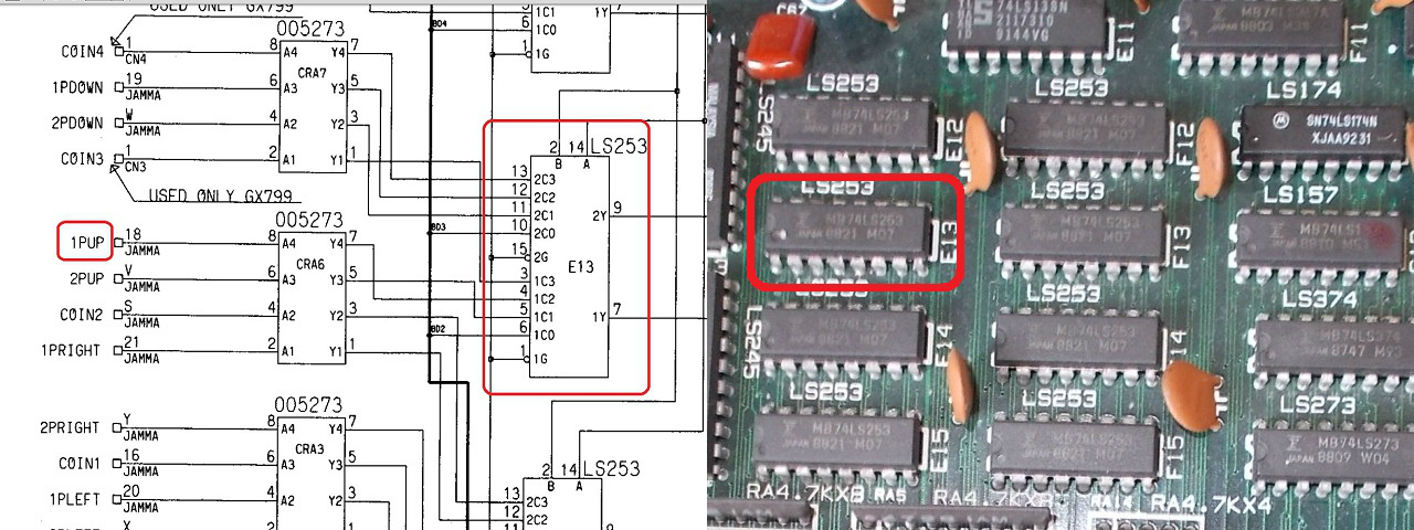
The last issue I had to fix was releated to inputs, P1 UP was not working.Using schematics I quickly found and replaced a 74LS253 @E13 with a bad ouput :
Board finally 100% fixed and another battle won against Evil Konami and Fujitsu with this big booty:
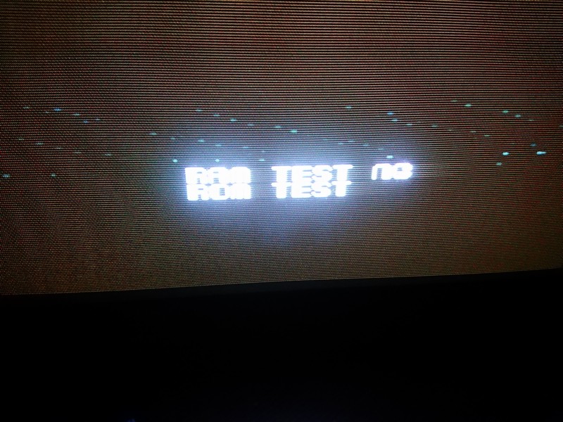
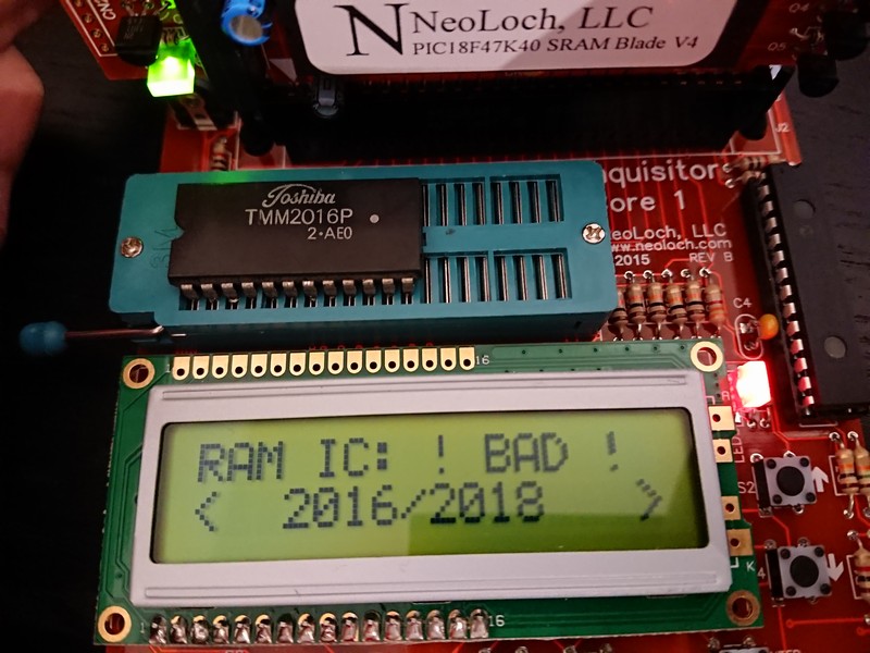
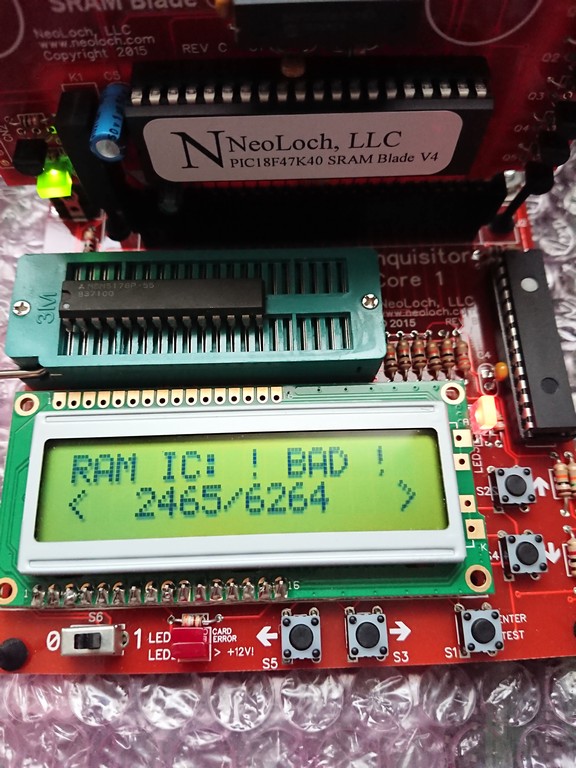
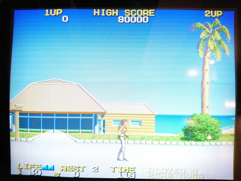
This game had been in my collection for about 14 years. I decided to make a play but the game displayed a RAM NG text and didn’t boot
After checking the schematics I decided to prove rams and some devices but the signals were healthy
Thanks to Kale from mame team, I discovered that the game does a simple check but decrementing some values in ram and read them back.
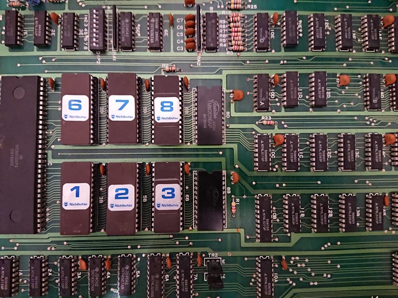
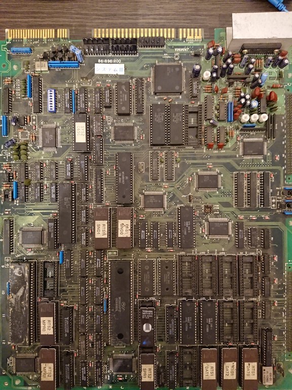
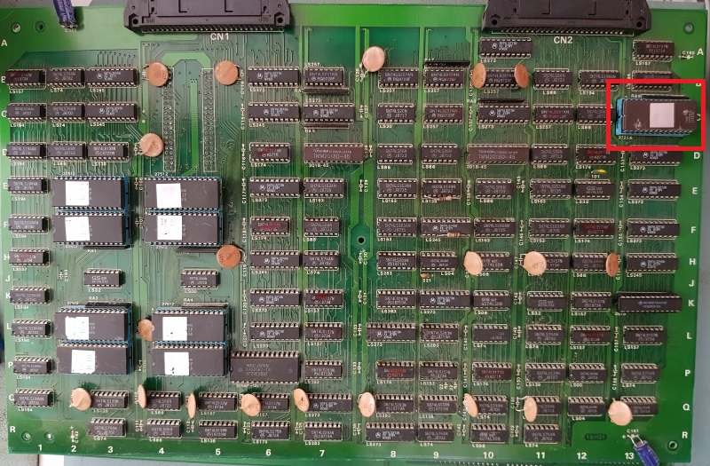
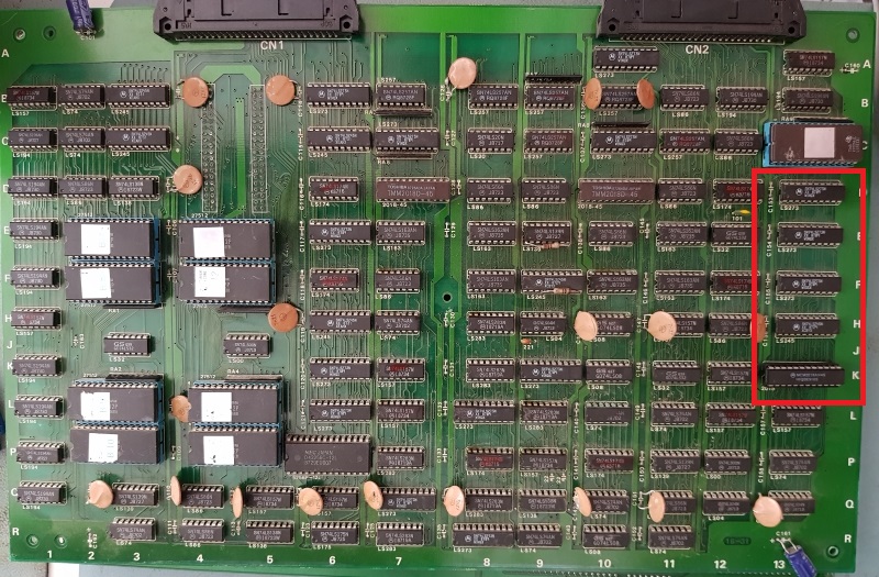
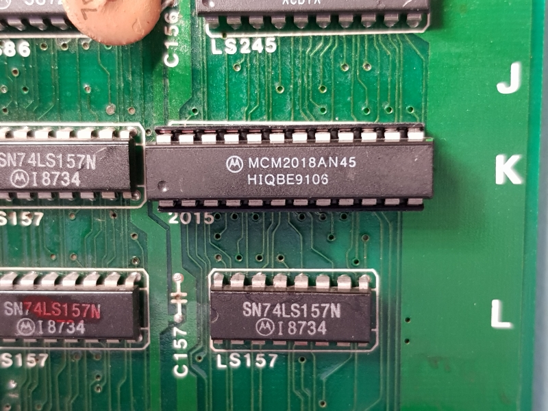
Therefore I decided to desolder the program srams to check if they were good. The game has only 2x 2016 toshiba rams.
This brand is known to be not really reliable in comparison to others
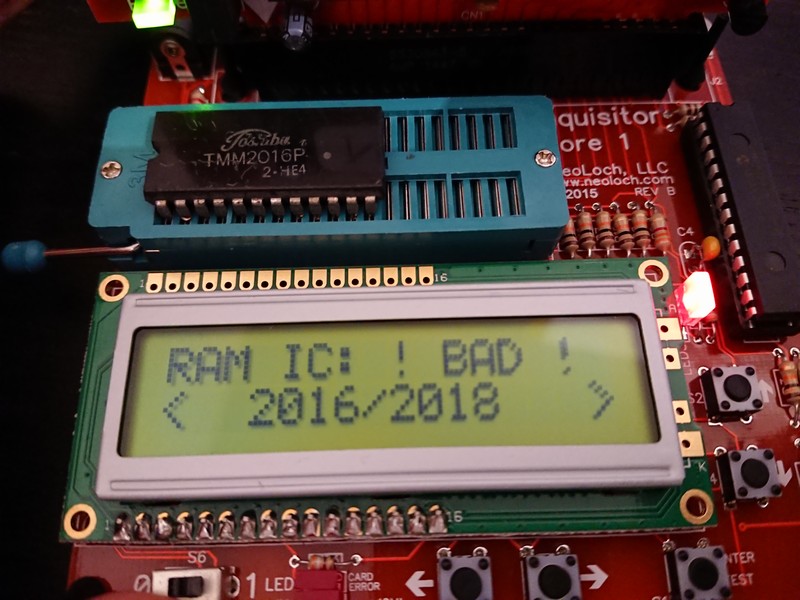
After checking the first one I got confirmation that it was bad
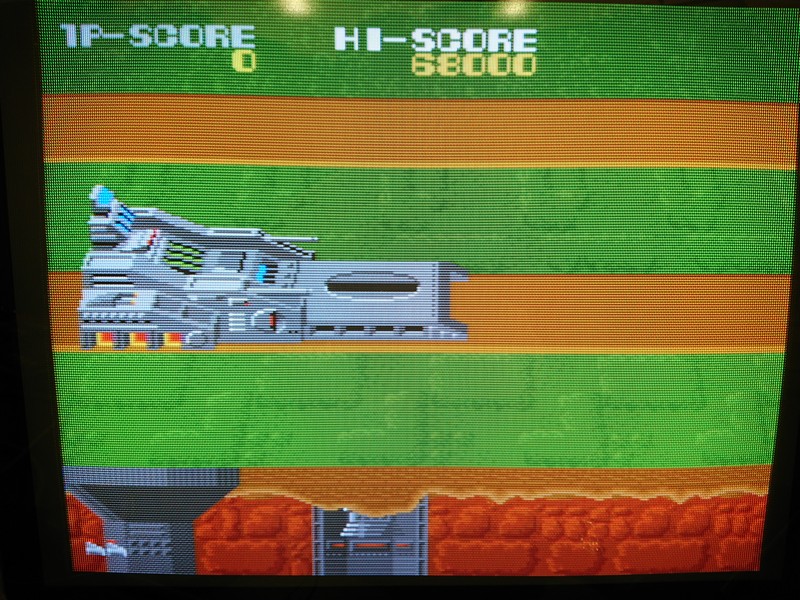
I resoldered it and this time the game booted with RAM NG briefly shown and behaved strangely. You couldn’t shoot and parts of the scrolling was repeating.
I decided to desolder also the second one since the game still complained about the ram.
Also the second one was bad!
After changing also this one, the game was 100% fixed
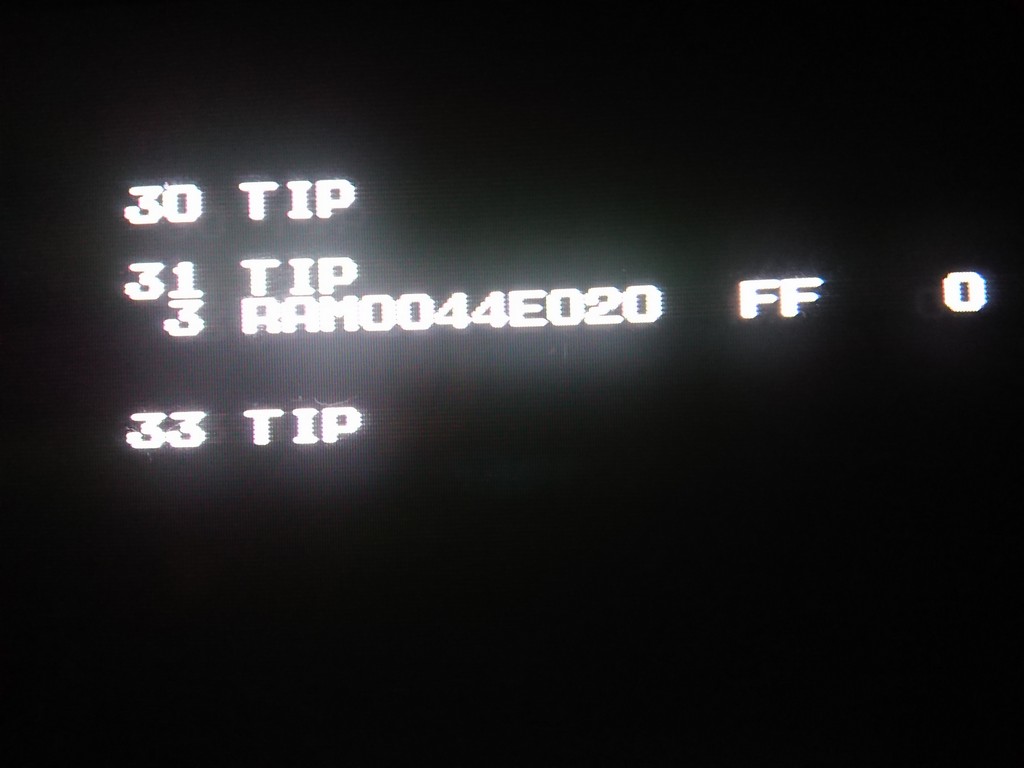
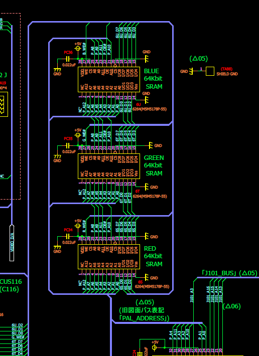
Using Mame source code with the memory map I could narrow down that RAM0044Eo20 was the colour BLUE ram
Desoldering it I could confirm it was bad
After replacing it I still got:
30TIP, 31TIP and 33TIP error
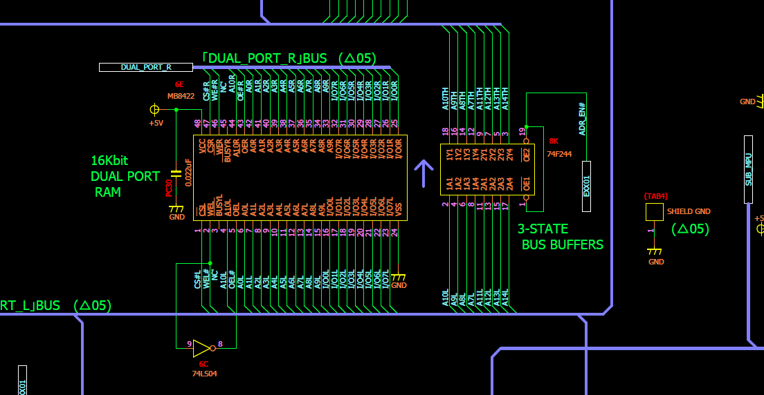
After discussing with Charles MacDonald he pointed me to the DUAL PORT RAM.
It checks if the last entry in RAM (460FFF) is zero, if so that’s an error (should be non-zero)
Then it checks if 460FF contains byte 6B, if it doesn’t that’s an error too
I started to probe around the dual port ram
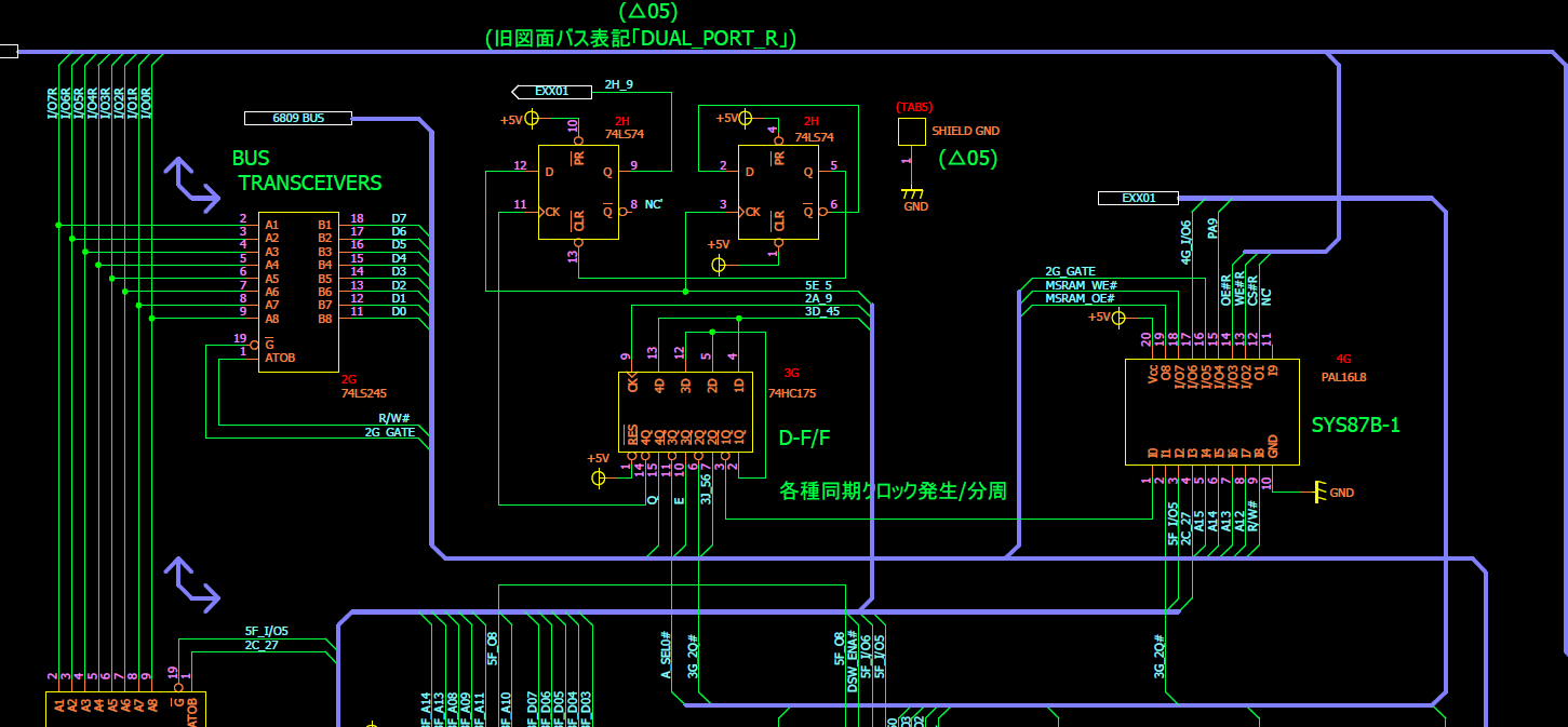
Until I found a stuck bit on the Left side of the Dual port ram which came from a 74HC175.
After changing it, the game booted but still with TIP33 error which could be erased by pushing the start button.
TIP33 is the error related to the EEPROM which is not inizialized correctly or contain some corrupted data. Normally you inizialize it only one time but everytime
started the pcb, I got this error and offcourse all the dipswitch settings couldn’t be saved correctly.
To cut a long story short, some smart guy changed the original EEPROM with a normal 8k SRAM!
I took a spare from a faulty final lap 3 and I could finally fix 100% the game
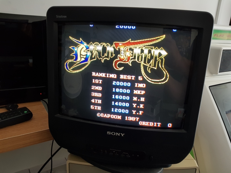
Although this is a bootleg it follows the original PCB closely.
Couple of easy fixes on this one.
First a character issue and second a sound issue.
As you can see in the video above, the screen is filled with “A”s and none of the text is correct
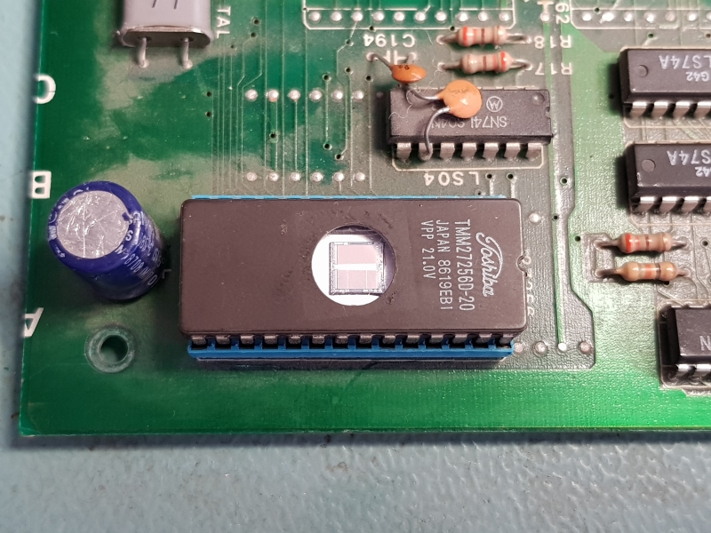
There is a seperate EPROM used for characters on this game.
Pulling this and reading back with my programmer yielded a valid dump for Black Tiger.
Checking the adjacent associated 74LS273’s and 74LS245 showed I had at least one pin floating.
I traced this back to a nearby TMM2016 which had D7 floating.
Replacing this fixed the screen
The sound issue was even easier. The sound program EPROM was completely smashed. Replacing it fixed the issue.