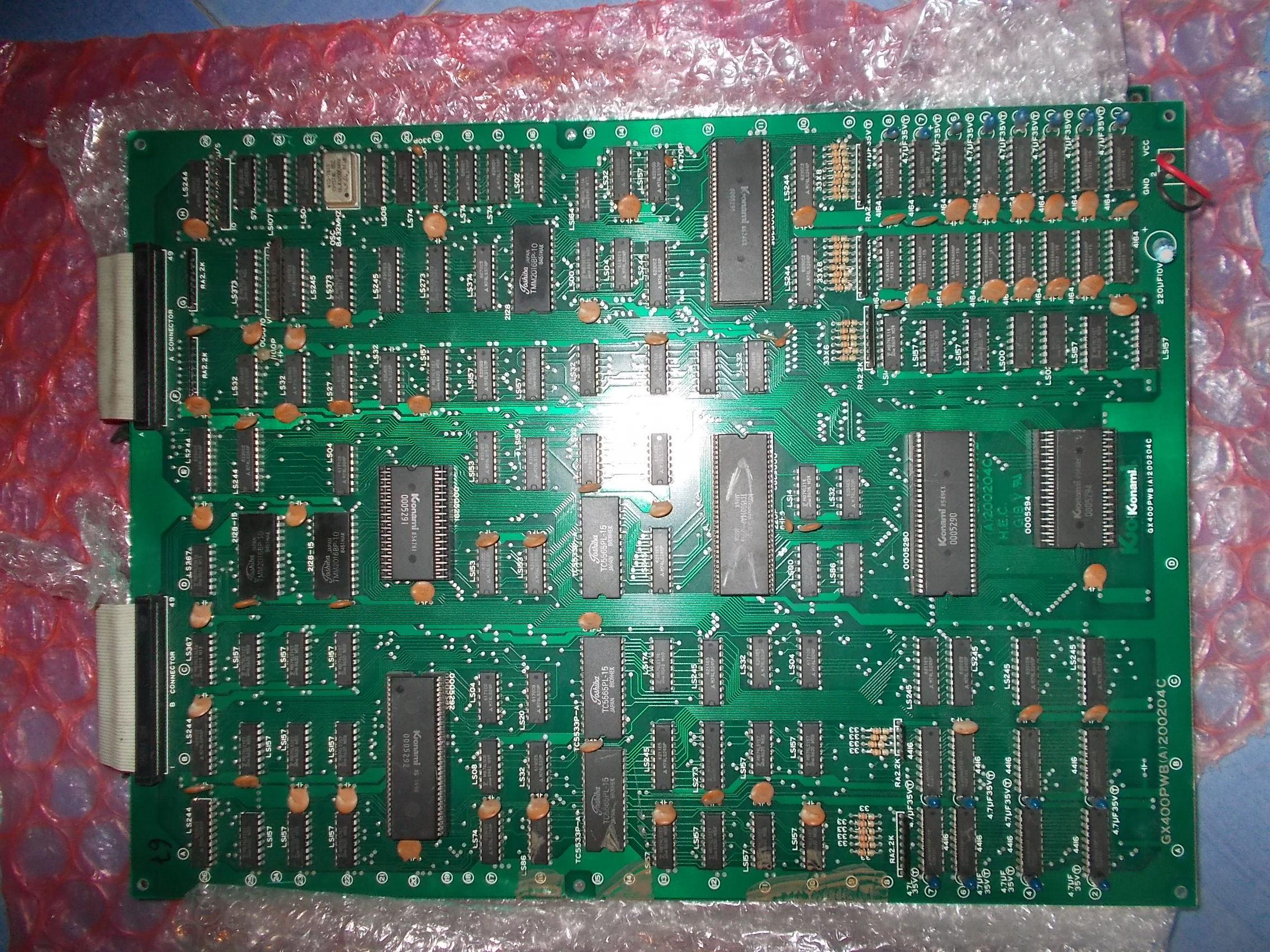
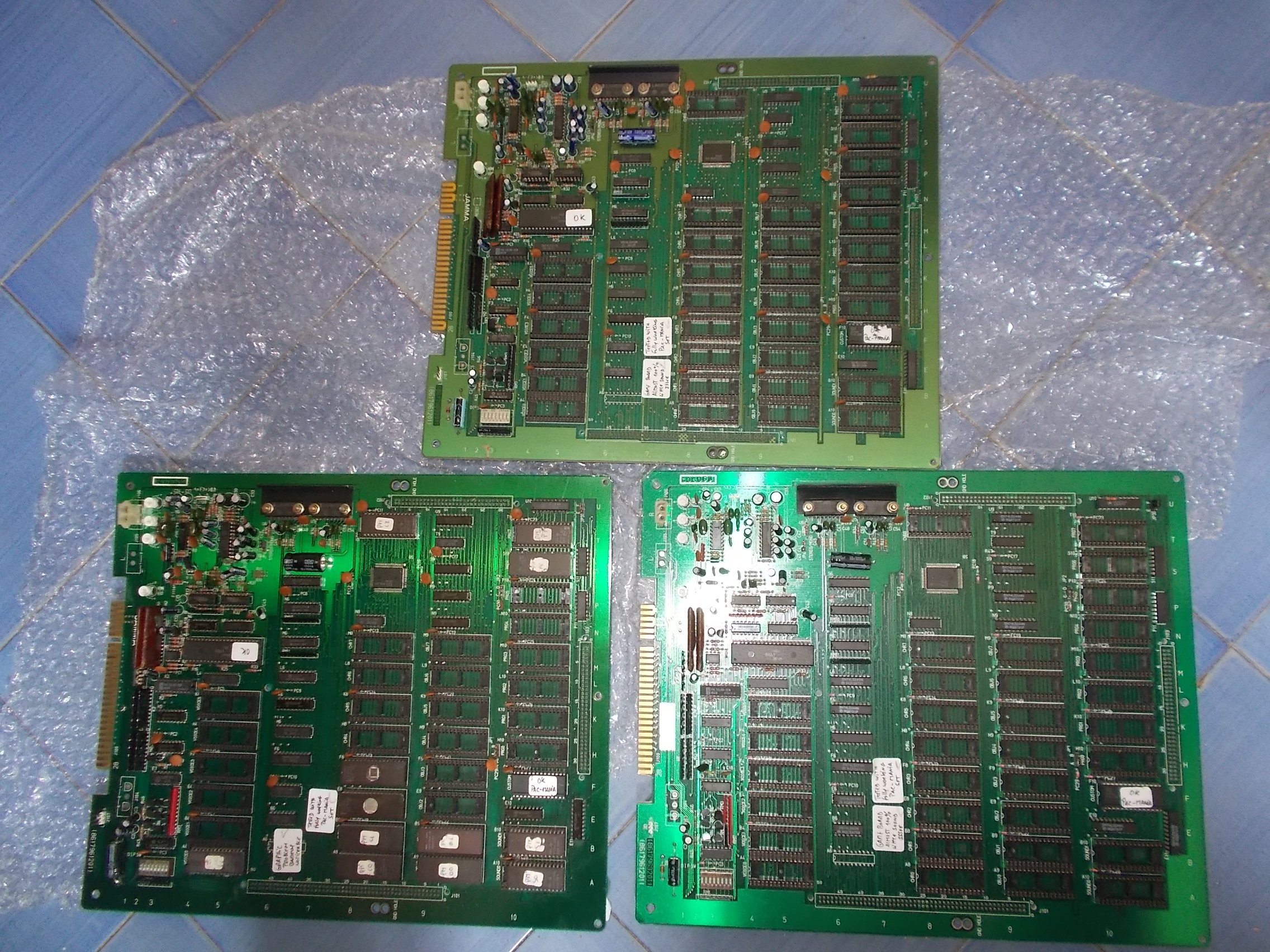
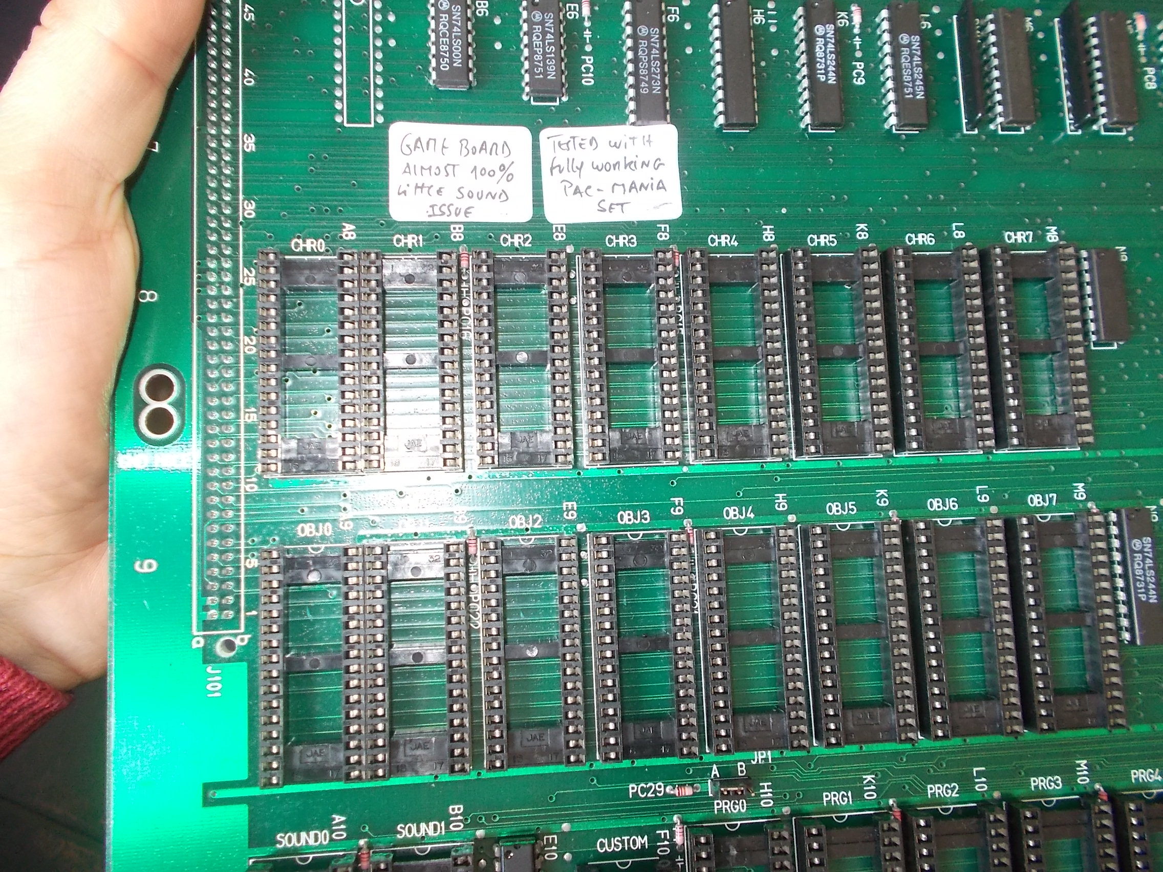
Recently I received a pile of faulty Namco System 1 hardware.I’ve been sent boards grouped by type because, as you may know, it’s a complex system made of a smaller CPU board and a bigger ROM board.I started to troubleshoot the latter.Three of them were tagged as “working but with sound issue” when tested with the same Pac-Mania ROM set :
The issues went from corrupted sound to lack of some music tracks :
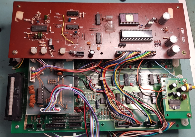
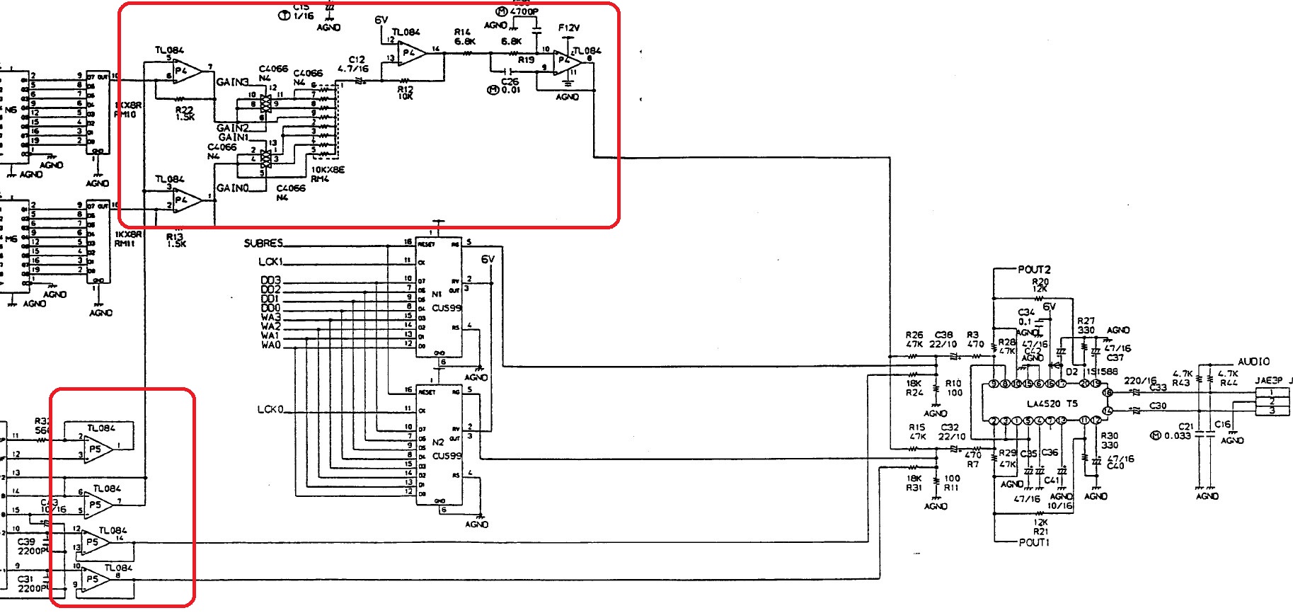
Using an audio probe I figured out the sound was properly coming out the YM3012 DAC but then got corrupted before being amplified.In the middle there are two TL084 quad OP-AMPs :
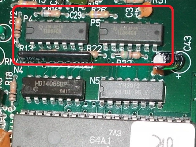
This part is well known to be very prone to failure especially the ones made by Texas Instruments manufacturer like in this case so I removed them all and they failed the out-of-circuit testing :
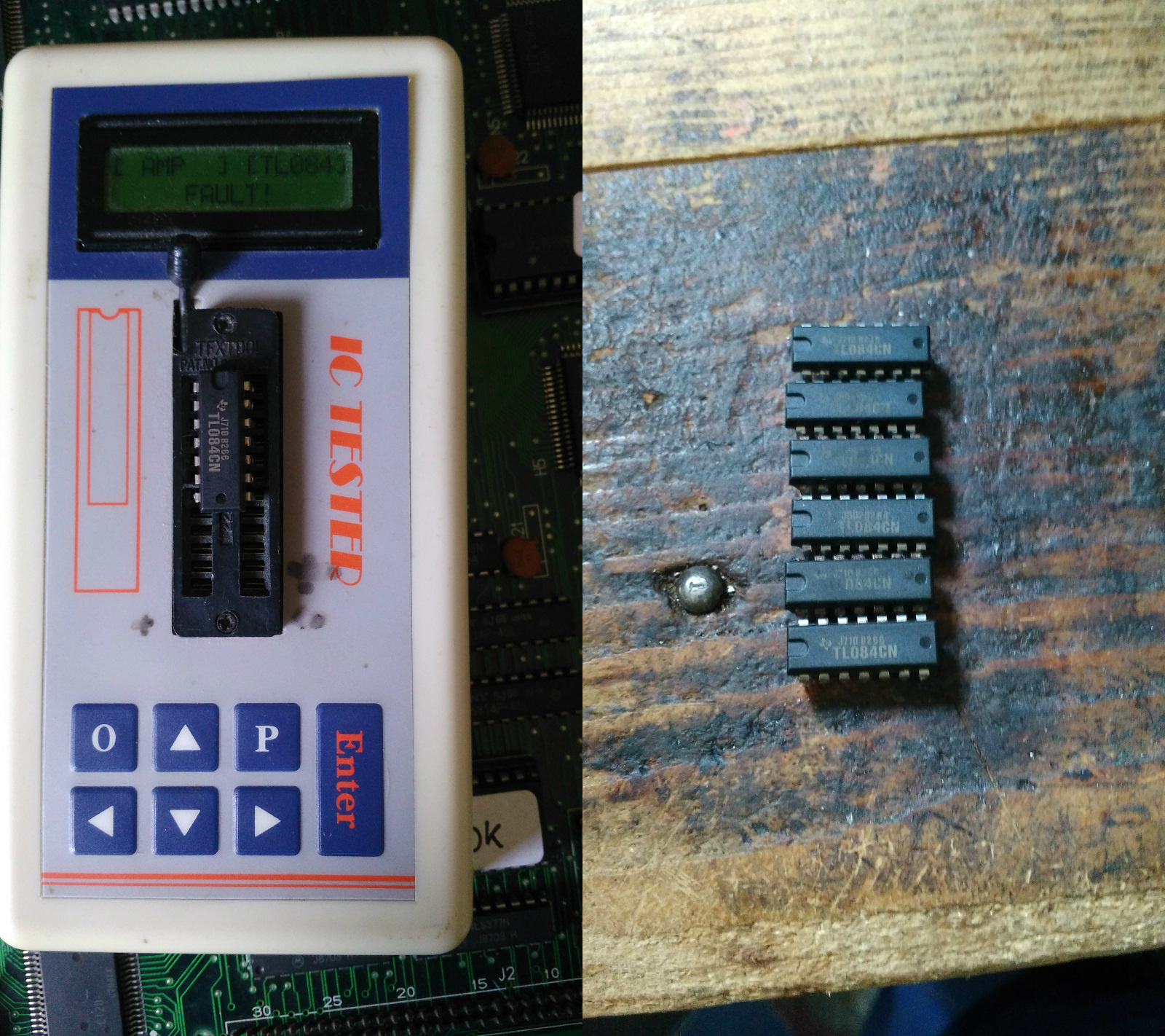
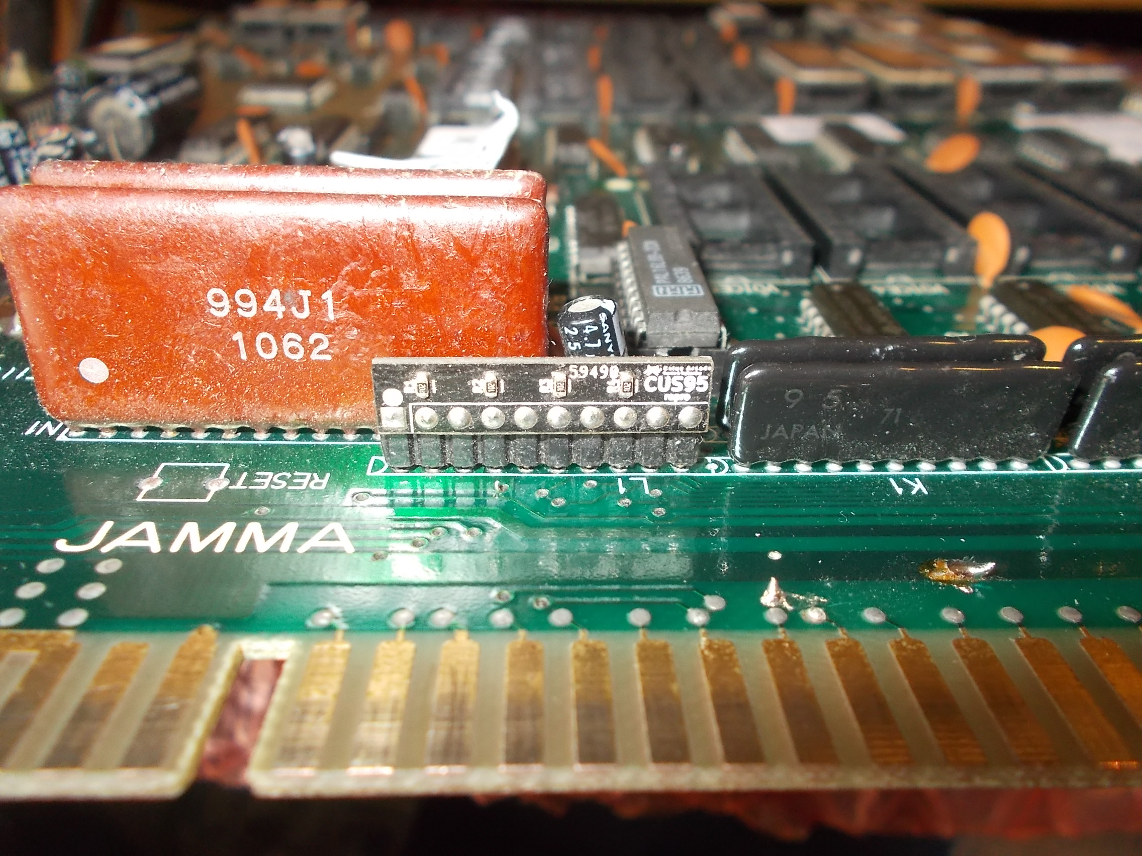
Replacing them with good ones restored full sound but while I was testing the boards I noticed some inputs were not working on one.A quick visual inspection revealed this :
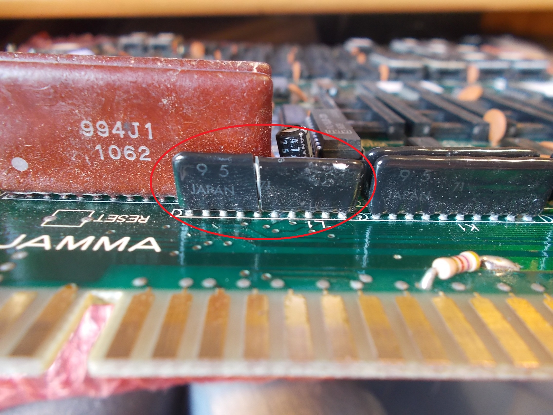
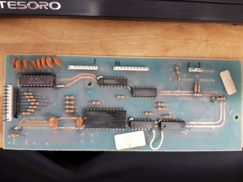
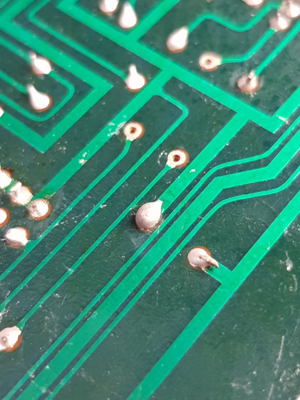
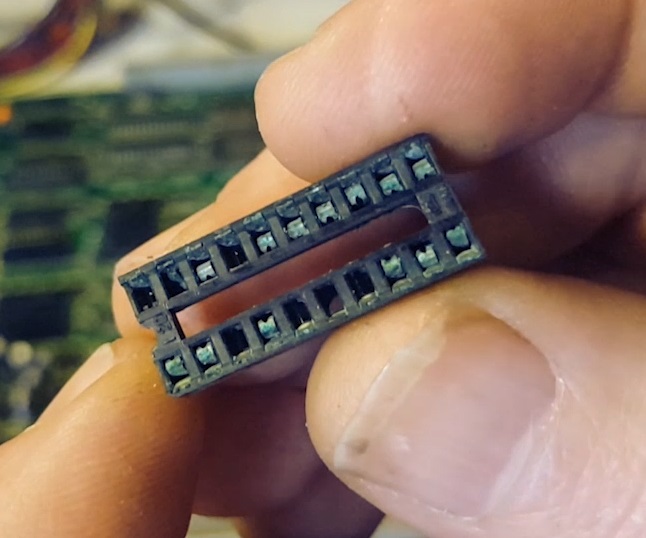
The custom resistors/capacitors array marked ‘CUS95’ was cracked in half.Not having a spare I decided to analyze the part and reproduce it :
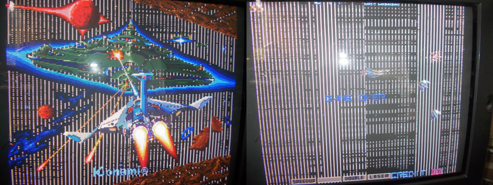
Three boards were fully functional now.The last one had also other issues besides sound not properly working as most of graphics were missing replaced by garbage, sprites were barely visible :
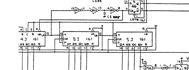
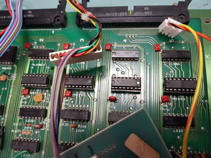
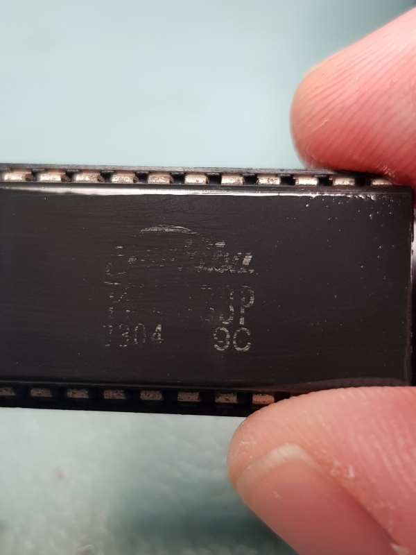
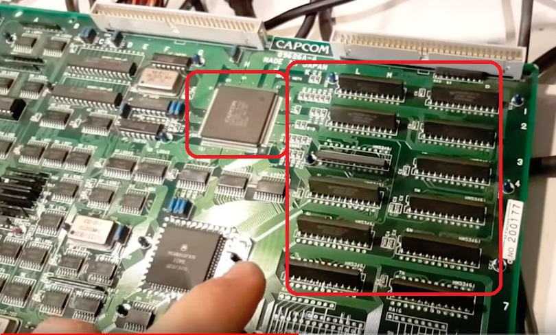
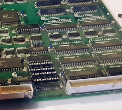
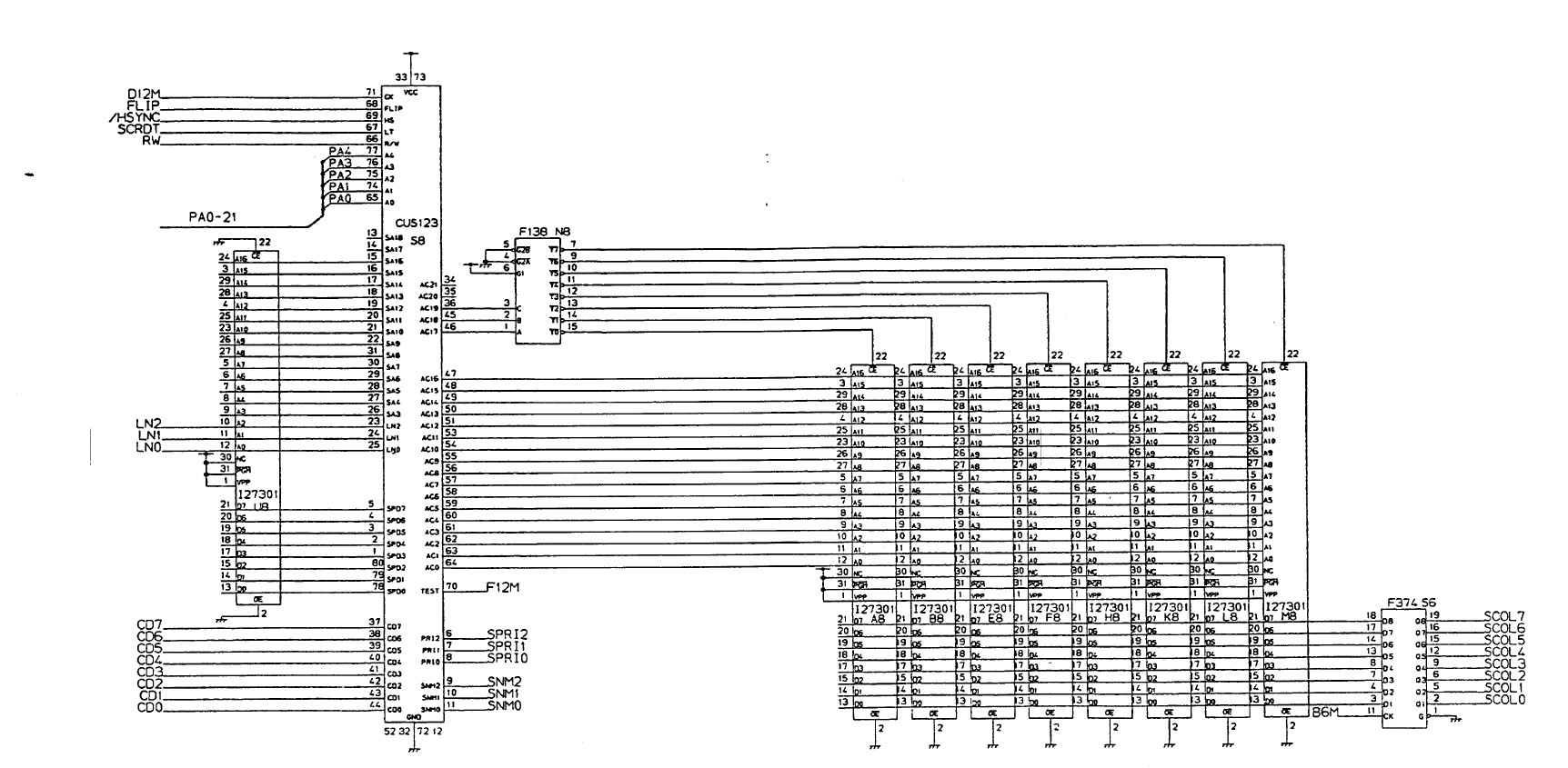
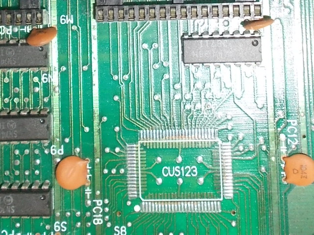
The tilemap generation is handled by the custom ASIC ‘CUS123’ (plus the ‘CUS133’ on CPU board) which generates the addresses to the character ROMs:
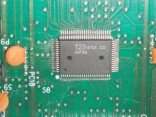
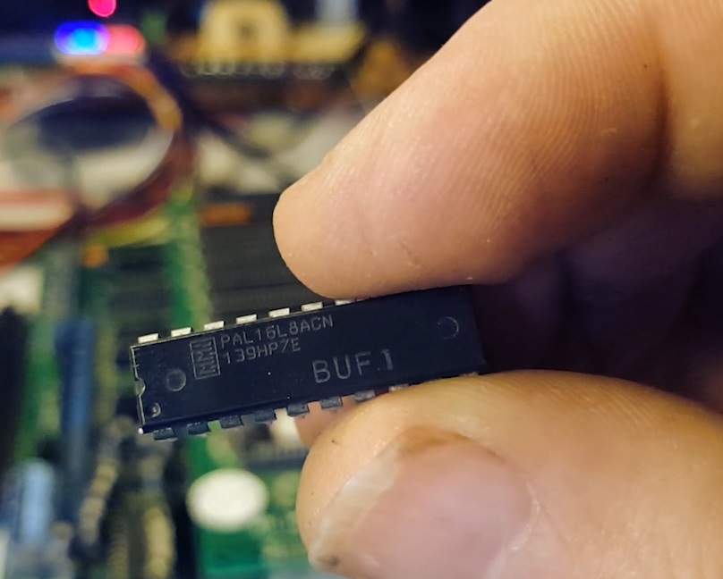
It was most likely faulty so I replaced it :
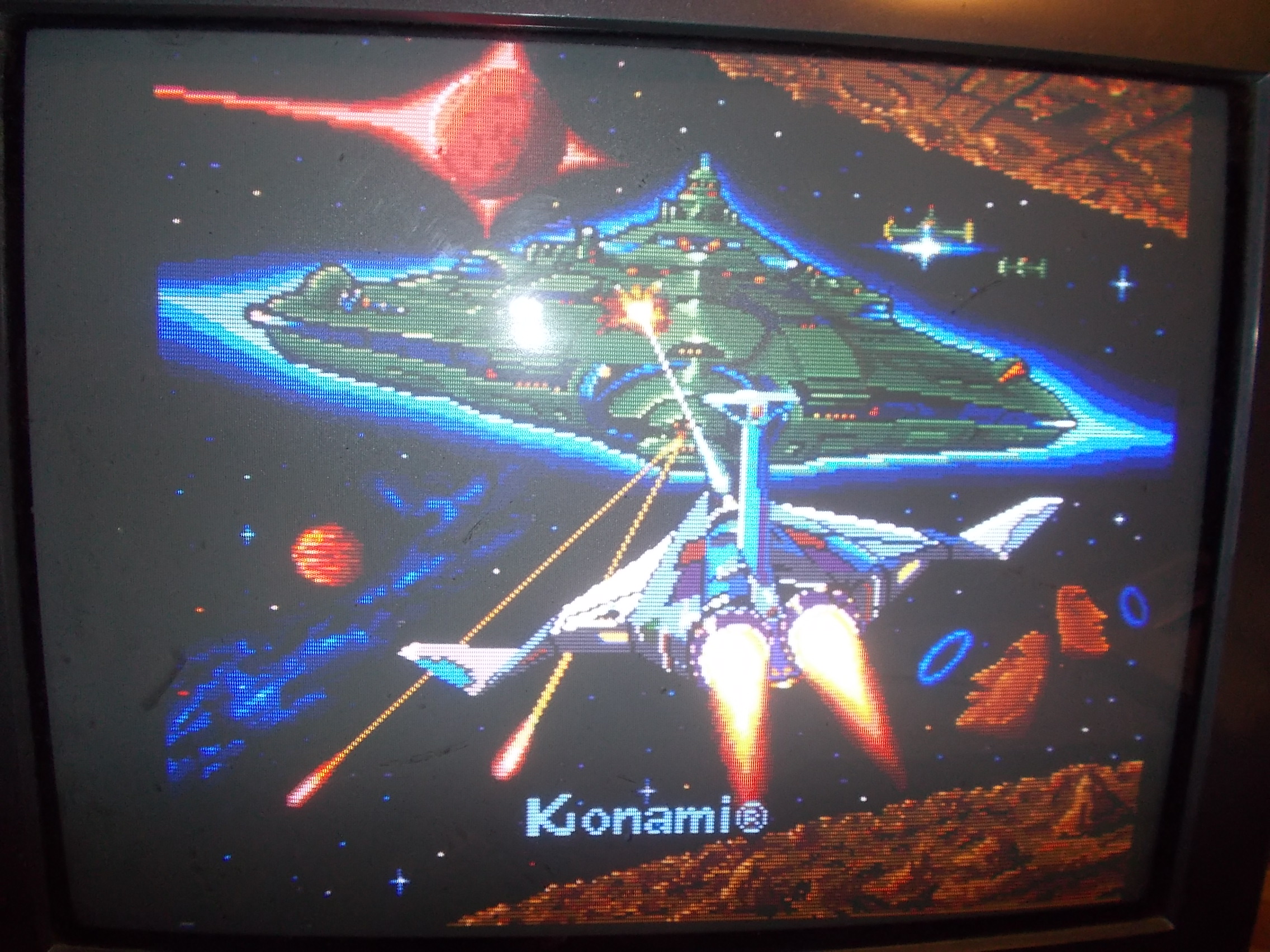
This restored the graphics and left me with the sound issue to fix, music were completely missing on this board:
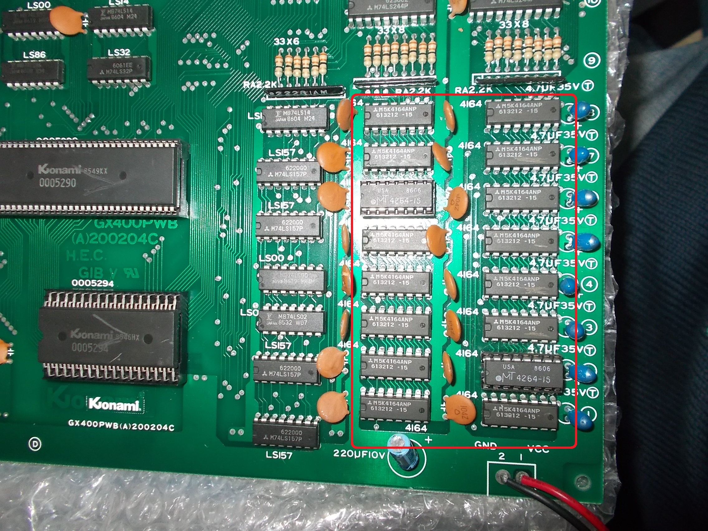
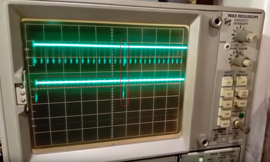
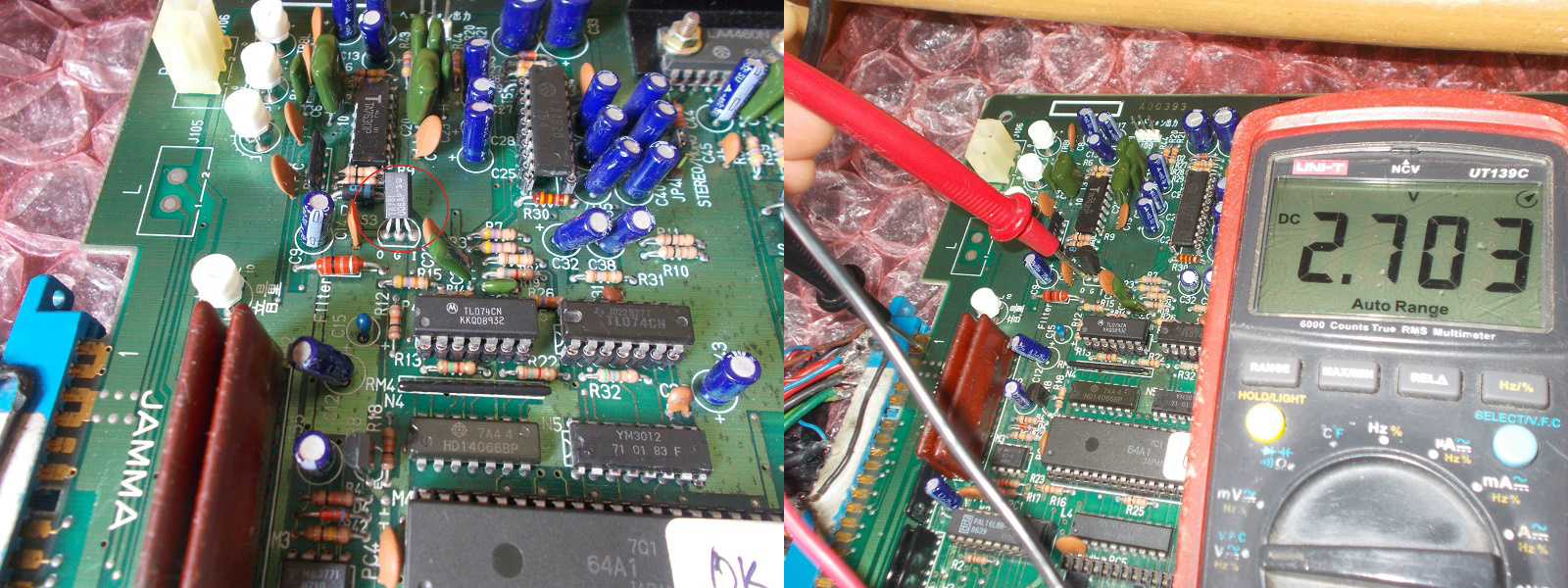
Replacing the two TL084 OP-AMPs didn’t do the trick this time so I went to probe the rest of circuit.I found that the 78L06 voltage regulator that provides +6 Volt to the YM3012 was outputting only +2.7 Volt :
Replacing it restored full sound.Namco System 1 multiple repair accomplished.