Nano SwinSID

 General  Comments Off on Nano SwinSID
Dec 092011
 

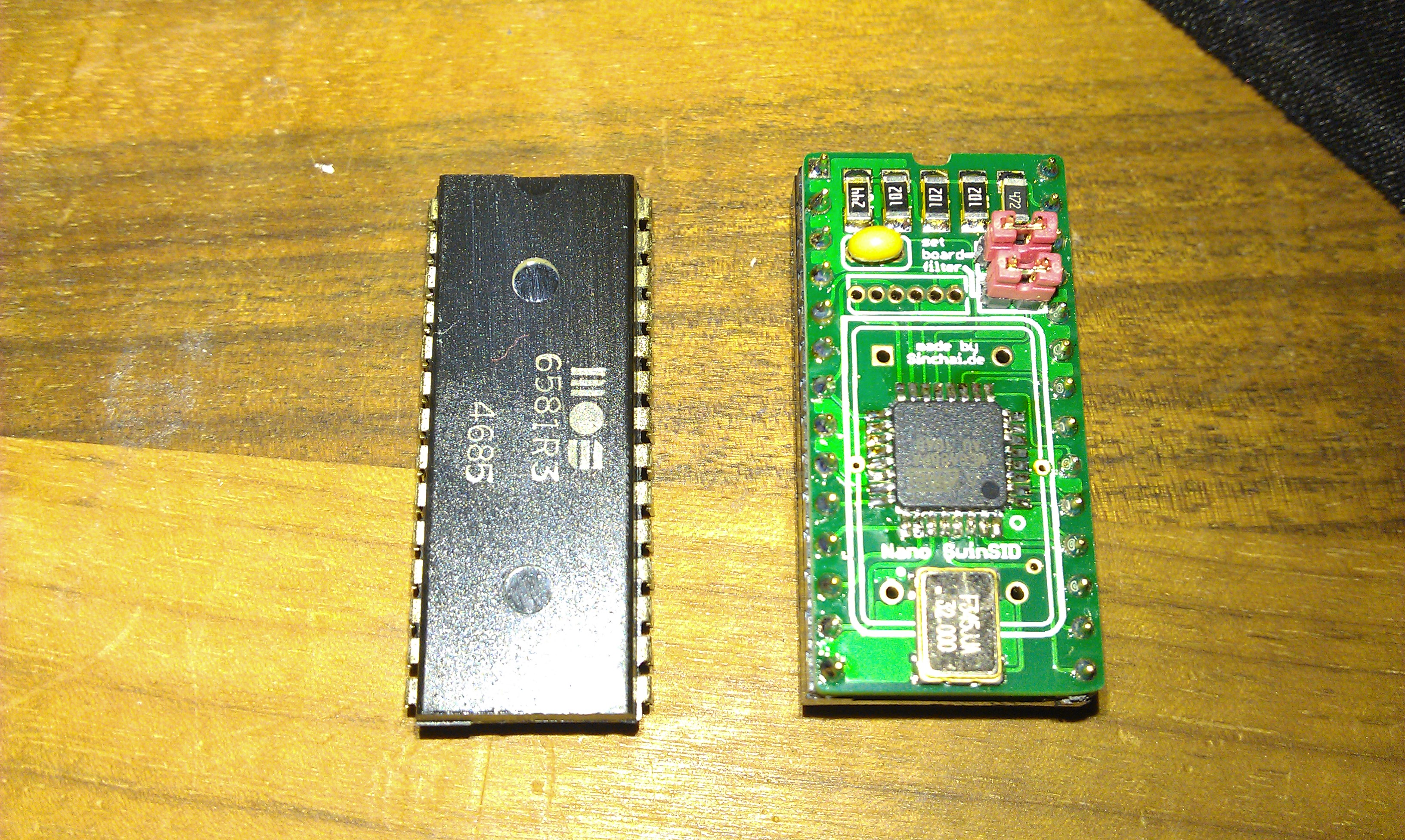
Got myself a couple of these SID replacements today.
I first saw them around April this year but have not been available to buy until now.
As you can see they are around the same size as the original and my first impressions are very good.

There are 2 jumpers on these.
The top one needs to be removed for older C64’s. It has something to do with resistor R3 and bring the volume level up.
The lower one is to switch between 6581 and 8580 emulation. A switch could also be added here to switch between then on-the-fly.

To test these against an original 6581 I used the SIDPlay program running from SD2IEC and fed both the samples into a PC to record them.
The most noticeable difference for me is the volume level on the original is far higher and I also think its a better, cleaner sound BUT as the SID chips are now going for stupid money by opportunists on eBay then this is a really nice alternative and one that will come in very handy in the future for many people.
Here are the .WAV files. Ive not converted these in any way, they were taken using Sound Recorder app that comes with Windows XP. The samples were taken directly after each other and no settings were altered at all.
Real SID
Nano SID

 Posted by at 6:19 pm
Dec 082011
 

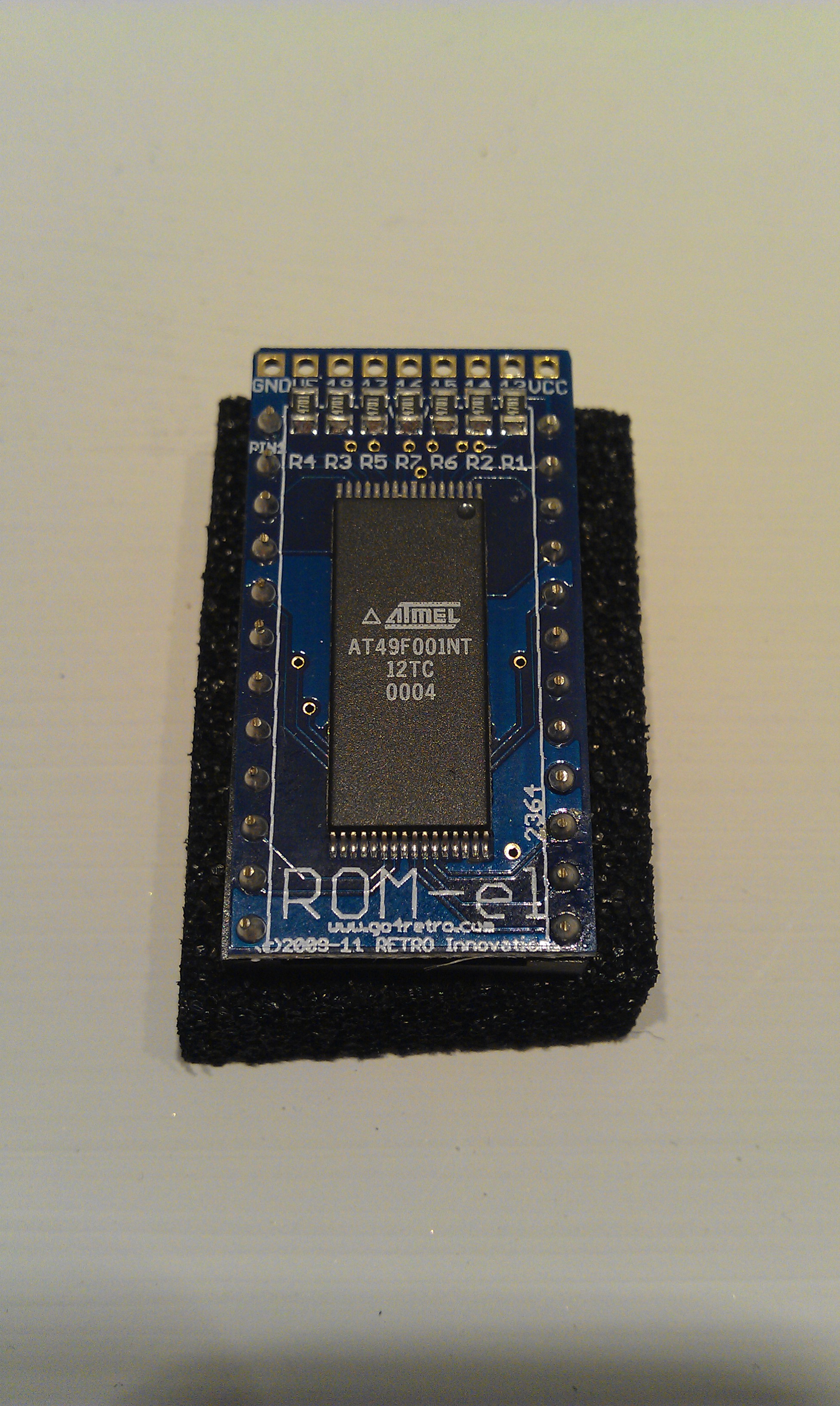
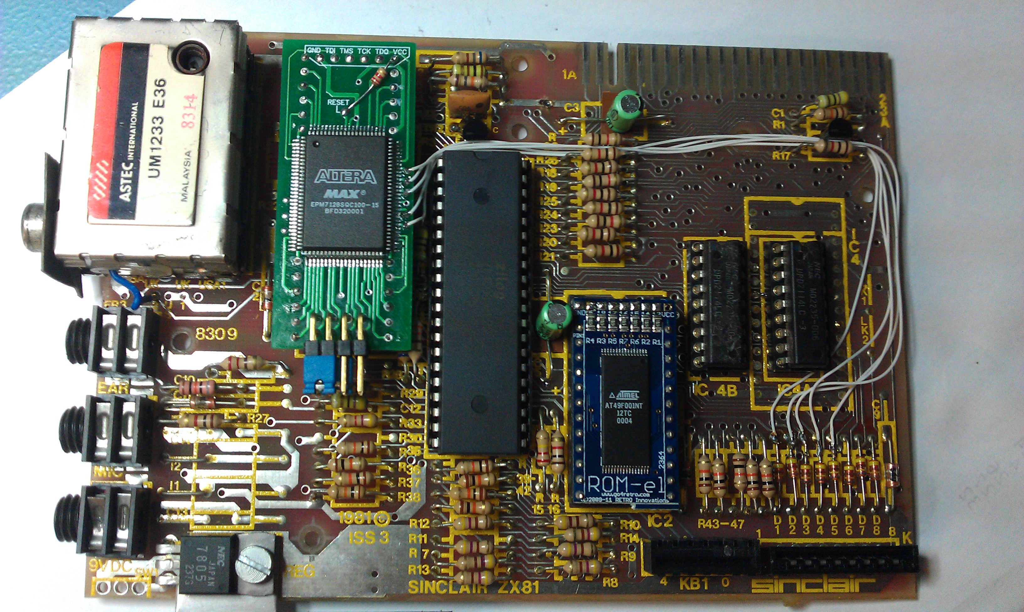
So my ZX81 ROM is apparently too slow to take advantage of my ULA so that means I needed an alternative. Unfortunately, as with the breadbin C64’s there is no EPROM alternative for the 2364 ROM but there is also no room in the ZX81 case for an adapter to fit properly.
Enter the ROM-EL 2364 from Retro Innovations.

This is a modern day solution for those old ROM’s and can be made switchable with a little extra work.
The only problem is an adapter is required in order to actually program the replacement. As the one I made was a complete hash I wont be taking any pictures of it but it served its purpose and now I have a switchable ZX81 BIOS.

My 81 is starting to look less like the original and more like a modern rehash but its working just great.

 Posted by at 8:58 pm

Commodore VIC20 in FPGA

 General  Comments Off on Commodore VIC20 in FPGA
Dec 072011
 

For some time now I’ve been watching the fpgaarcade website and have even bought some of Mike’s replacement C64 PLA chips.
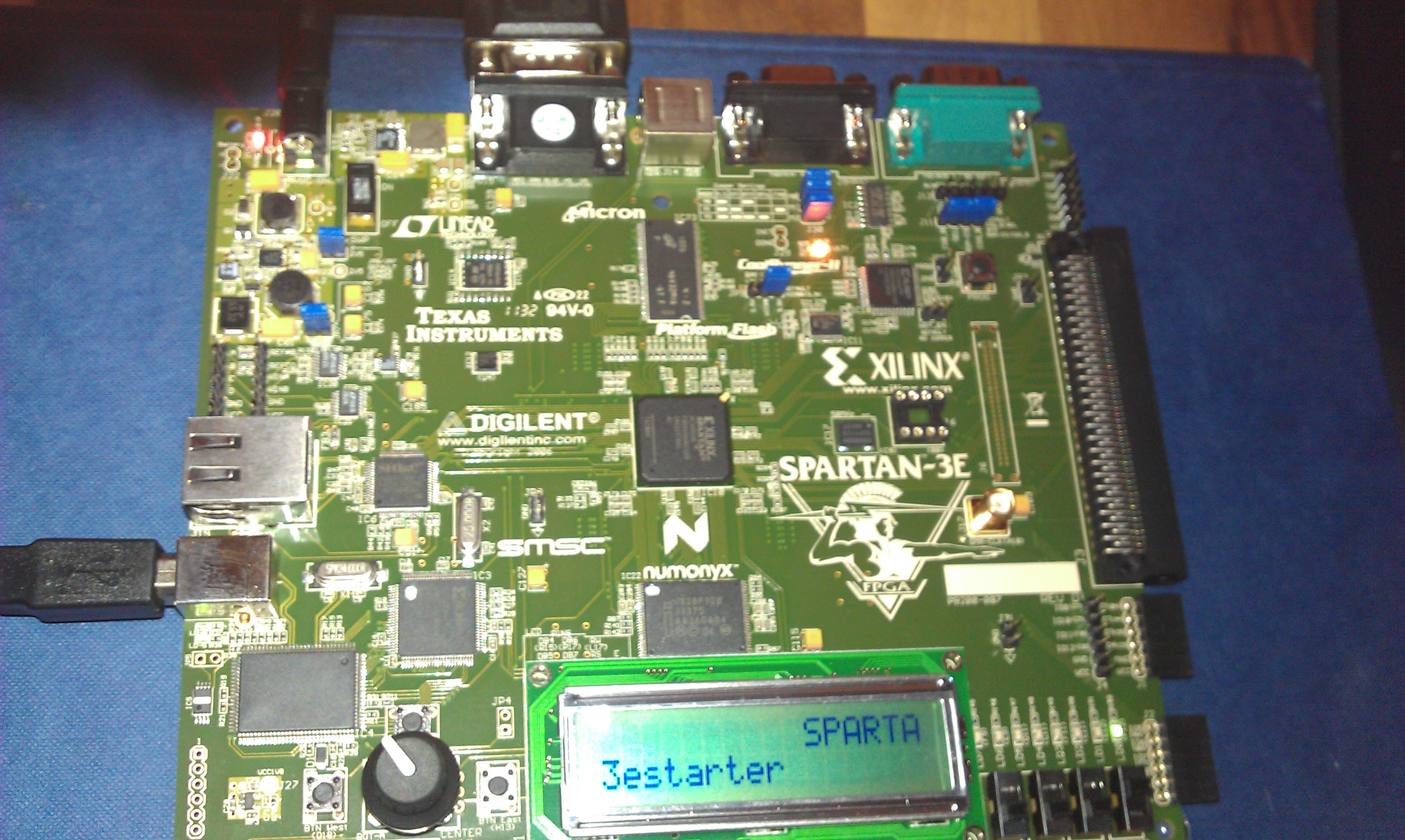
Recently I got my hands on a Spartan 3E FPGA development board and thought id try out Mike’s FPGA implementation of the VIC20.

Following the instructions provided it was a breeze compiling and transferring the VHDL.
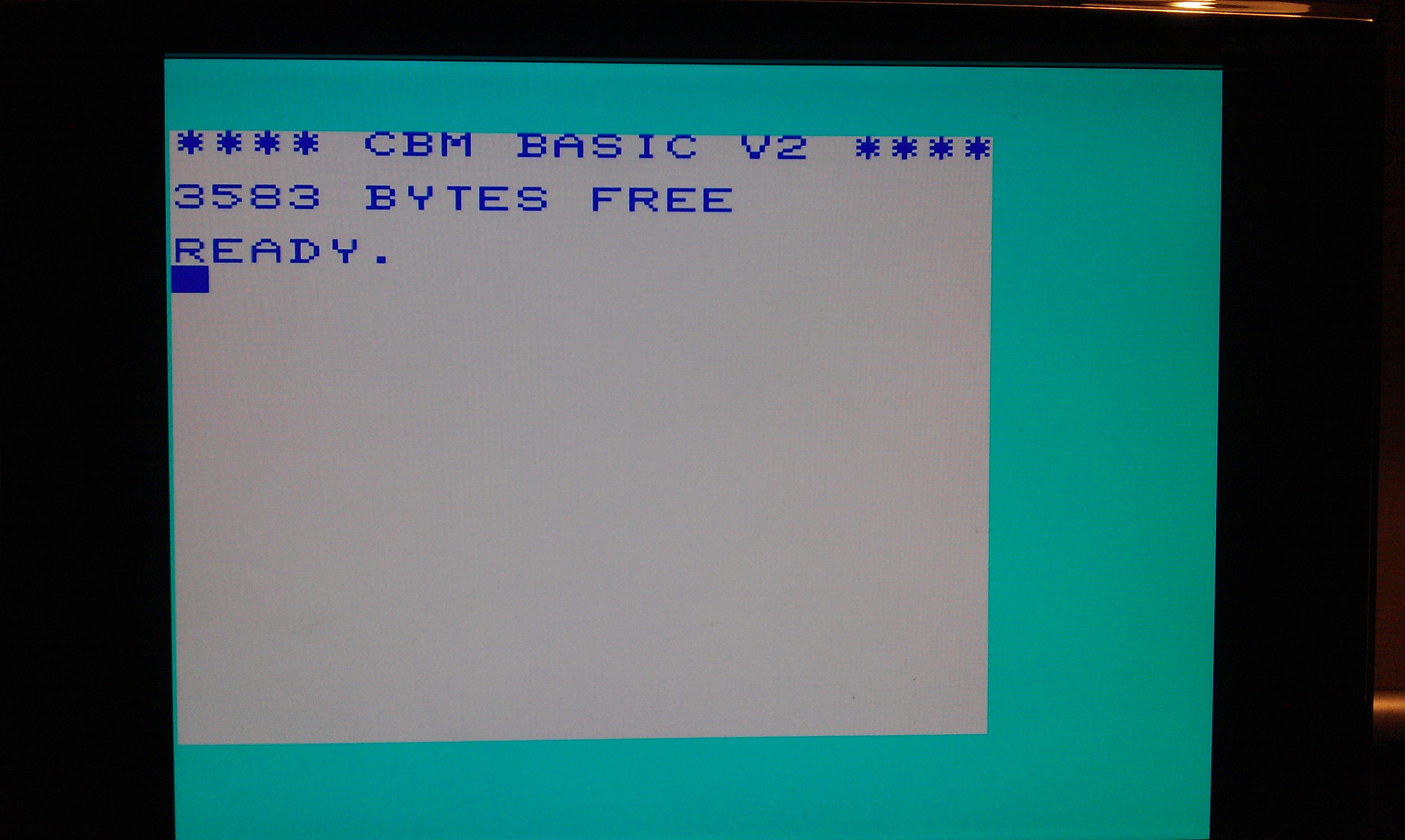
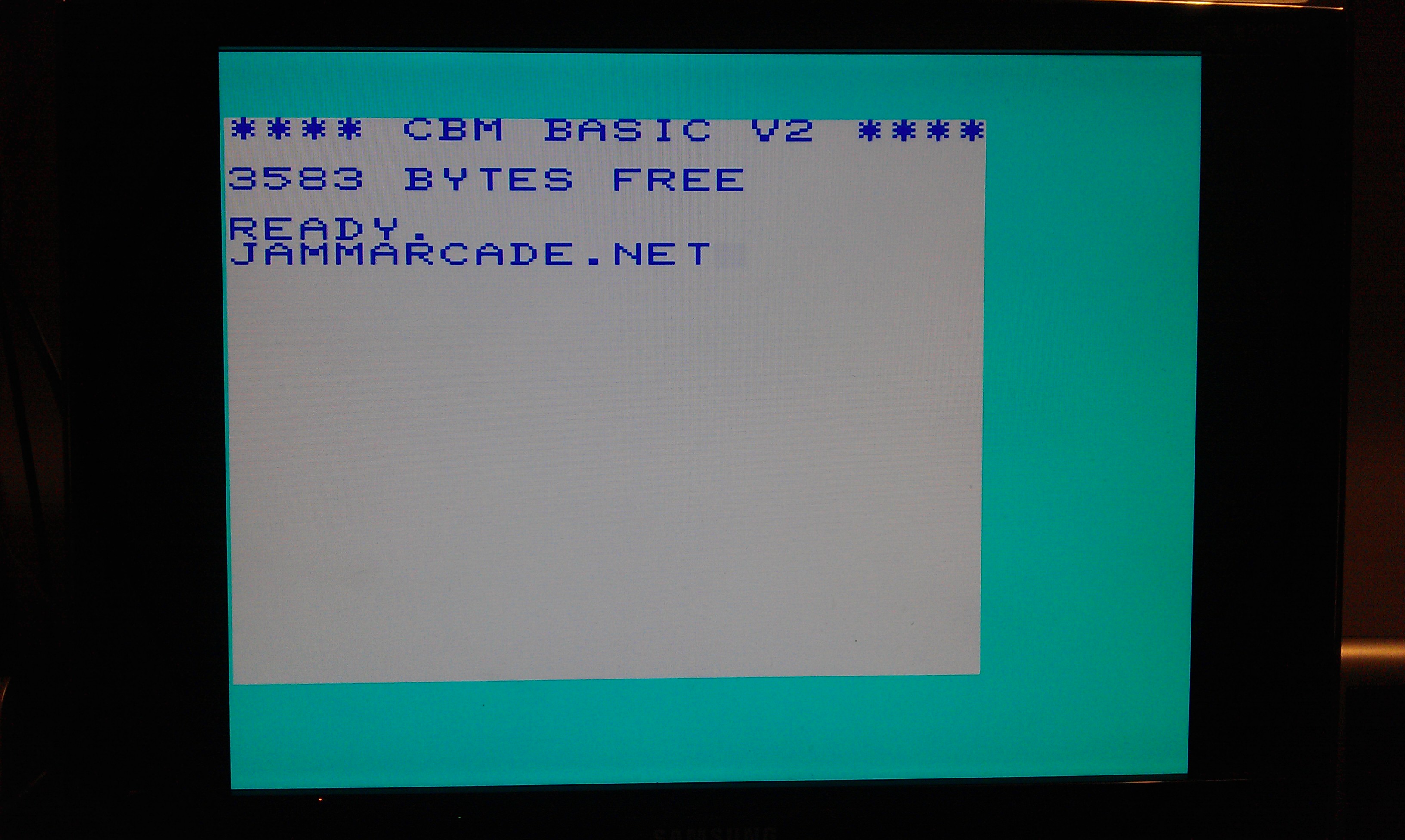
Plugging in the VGA cable and setting the on board switches to 31khz I was greeted with

On my monitor here the screen is offset slightly but im told another monitor may yield better results.
The Spartan development board also has a PS/2 port which when I plugged in a keyboard was able to use the VIC20 as I would a real one.

This thing is so good that I can even upload 4 converted cartridges into the on board flash memory and run them at the flick of a switch. Once I get my serial cable built ill try that out too.

Now, on with learning VHDL, its not going well.

All credit goes to Mike at FPGA ARCADE

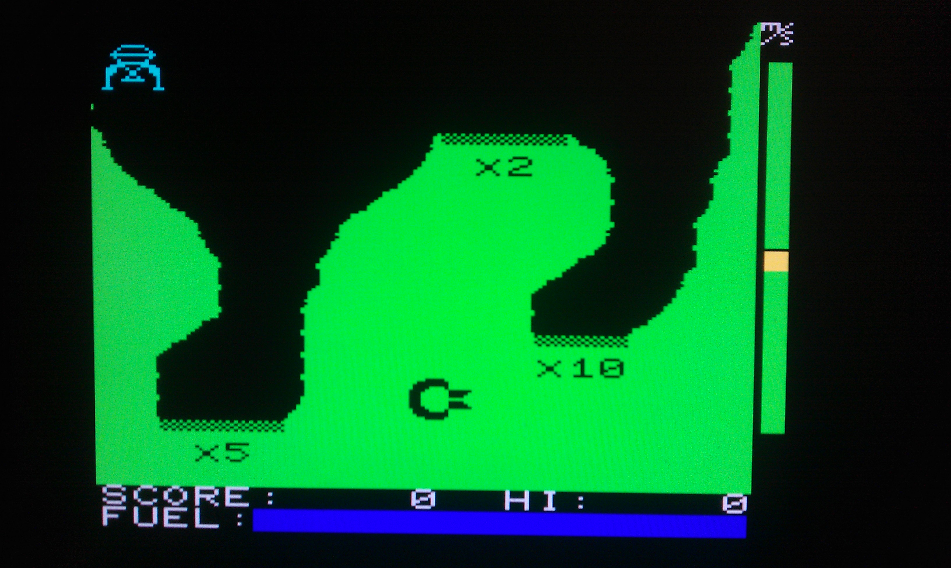
EDIT: Got a serial cable made up and flashed over the Jupiter Lander game as described with the VIC20 VHDL source, works pretty well.

 Posted by at 8:06 pm

PLS100 chips

 General  Comments Off on PLS100 chips
Nov 232011
 

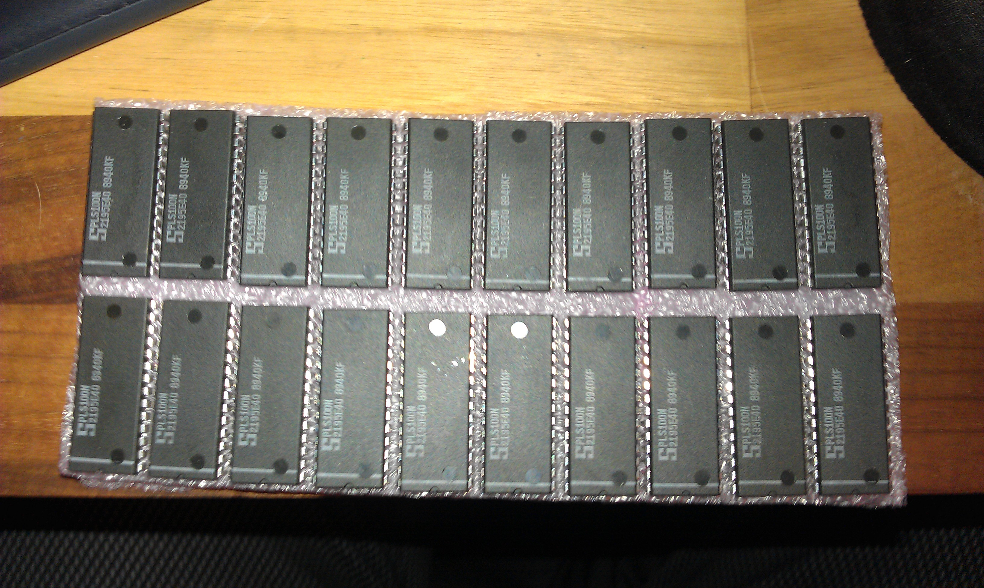
Today I received a job lot of 20 x PLS100 chips that I got from eBay recently.
For those that aren’t aware, these are what was used as a PLA in the older breadbin Commodore 64’s and are probably the most common failure in the machine as they tend to run hot.
Ive got the JEDEC fuse map from a genuine C64 PLA and have tested with no problems. These should keep mine and RCM’s Commodore’s going for a while longer now

 Posted by at 4:37 pm
Nov 122011
 

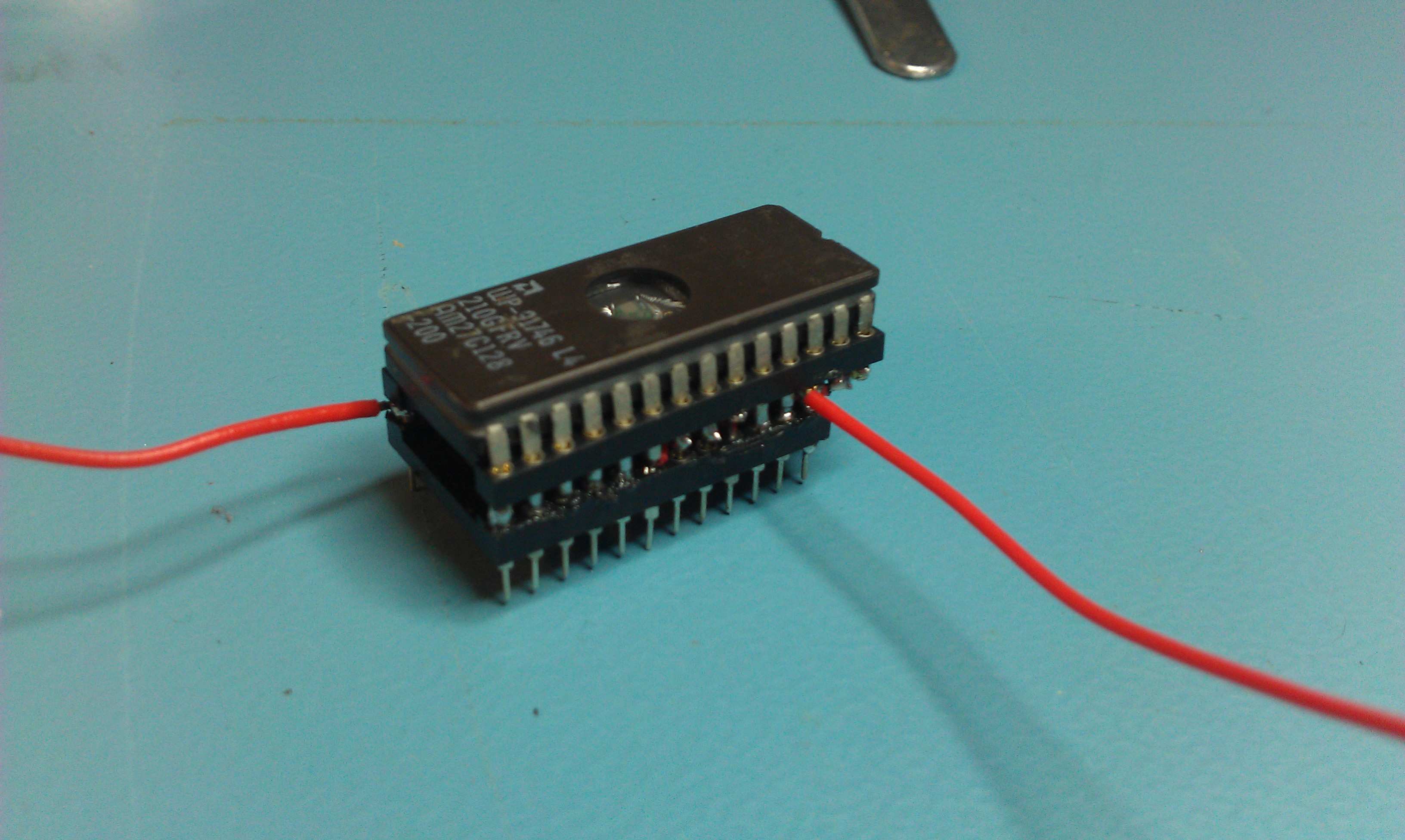
Today I finished my adapter to make a breadbin 64 accept a 27C128 EPROM.
The standard kernel ROM is a 2364 pinout and is 64Kb. To fit both the original kernel and the JiffyDOS kernel on obviously we need a ROM twice the size.
The problem is the 2364 is not compatible with any EPROM pinout unlike the C64c so this adapter is necessary.

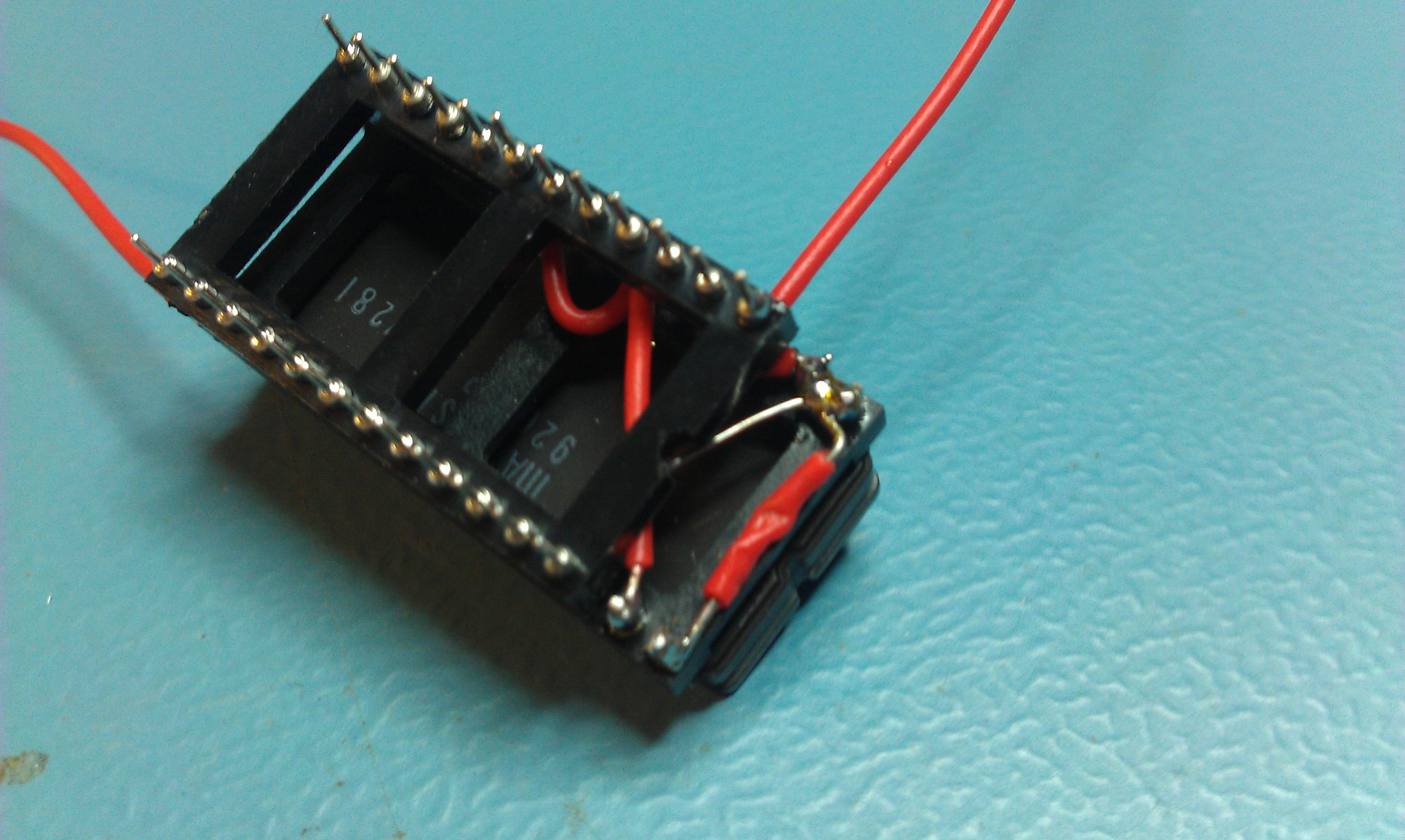
I used 2 turned pin sockets, a 24 pin and a 28 pin one.

  • On the 28 pin socket cut pins 20, 23 & 26 short,not completely off but short enough not to make contact with the pins on the 24 pin socket when pushed together.
  • Connect pin 1 to pins 27 and 28
  • Connect pin 14 to pin 20

Get the 24 pin socket

  • Connect pin 28(VCC) of the 28 pin socket to pin 24 of the 24 pin socket
  • Connect pin 2 of the 28 pin socket to pin 21 of the 24 pin socket
  • Connect with 23 of the 28 pin socket to pin 18 of the 24 pin socket
  • Attach flying leads from pins 14, 26 and 28 of the 28 pin socket, these will go to your switch.
    You can also fit a 4.7k resistor between pins 26 and 28 which means you don’t need that extra flying lead from pin 28 to the switch, just makes it that little bit easier.
  • Mash the two sockets together lining pin 14 of the 28 pin socket to pin 12 of the 14 pin socket.
  • Fit your 27C128 eprom and you should be good to go.

My first attempt works well but isn’t the neatest. If I make another and I almost definitely will, it will be neater.


 Posted by at 6:49 pm