Porchy

Fluke 90 repair log

 Equipment Repair Logs, Repair Logs  Comments Off on Fluke 90 repair log
Aug 232015
 

I’ve come to the conclusion that I will probably never own the 6809 pod for the Fluke 9010. Accepting this fact led me to find a Fluke 90 6809 tester.
These things are a far cry away from the capabilities that the Fluke 9010 offers but they still offer some decent functionality.

I got one of these from the US quite recently and it was, as far as I could tell, unused. It was still in its wrapping and is in pristine condition.
Ive got a couple of games that use 6809 CPU’s to hand so thought I would give it a try out.
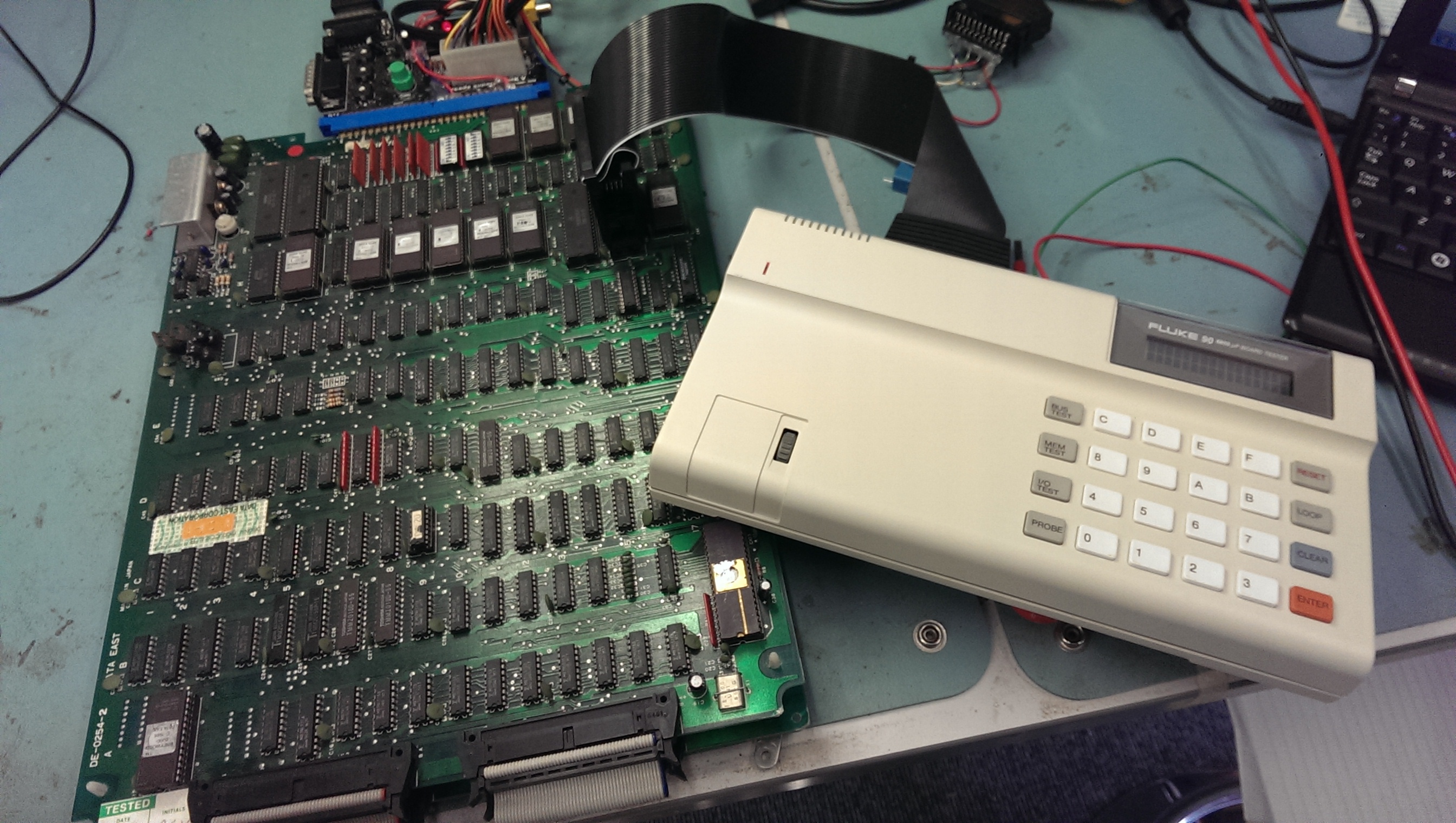
IMAG1483

I first pulled Breywood out and clipped the test clip over the CPU but I got an “ERROR 4 UUT CPU BUS REQUEST FAIL”. This means that the /HALT signal cannot be driven.
Its at this point I found the “Getting Started” guide online.
This states that the /HALT line cannot be tied to VCC. Breywood does indeed have this pin tied directly to VCC (and not even via a resistor).
Thinking about it I probably caused this fault by not reading the manuals prior to using it.

Time to break this thing open.
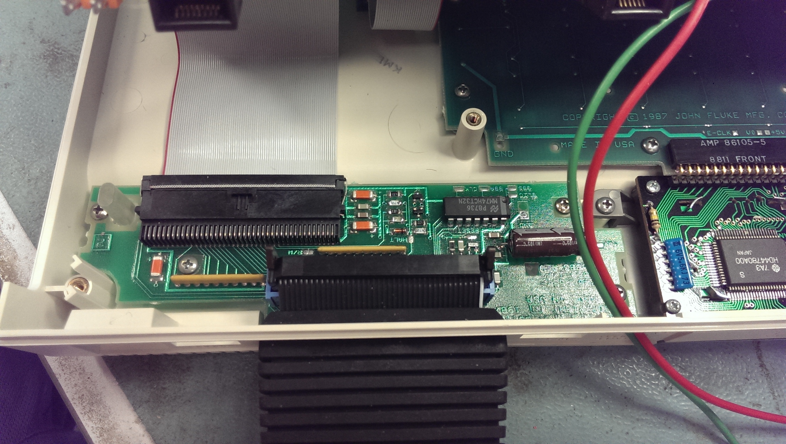
IMAG1485

The Fluke 90 needs to be able to drive the /HALT pin and it also does a check on startup that it can do this. If it cannot drive the pin then it flags up the fail message.
As you can see in the above picture there are a few discreet components for this section. Doing some quick poking around with the logic probe revealed that the emitter on one of the NPN transistor (towards the top on the picture) was dead. I removed the transistor and checked it out of circuit, sure enough it was dead.
I replaced both of these transistors just in case and tested.
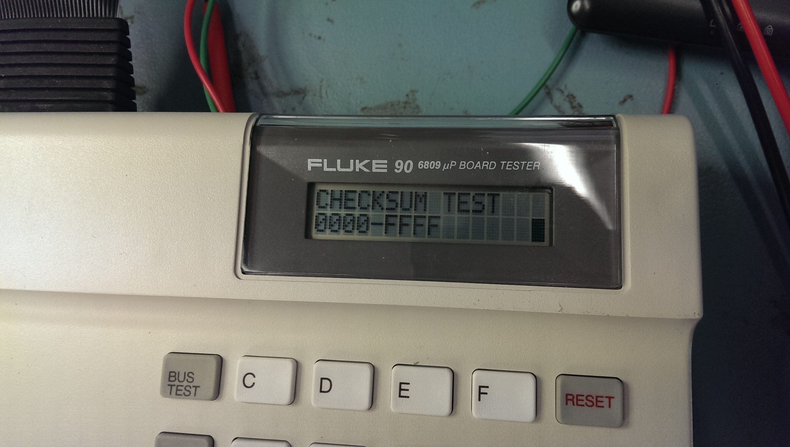
IMAG1482

Everything now seems to be working fine.
I’m really pleased with this unit. It has some nice features like being able to set breakpoints (if connected to a PC)

 Posted by at 4:39 pm

Quick ROM ident program

 General  Comments Off on Quick ROM ident program
Aug 152015
 

I loved the old WinROMident program for its quick usage but unfortunately it hasnt been updated in a long time.
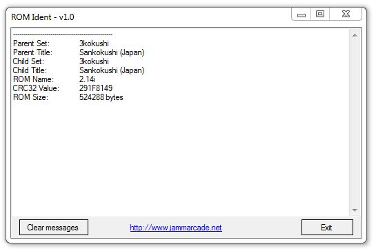
Ive made a new drag and drop program that uses Romcenter .DAT files
romident

It doesn’t yet support zip files, only single files.
As with everything I make it requires .NET (v4.5) installed on your computer and it probably has a load of bugs too.
Its minimal and quick which is exactly what I need.

Can be found in the Downloads/Software section

 Posted by at 4:20 pm

64k expansion dump added & Rastan dumps tested

 PAL Updates  Comments Off on 64k expansion dump added & Rastan dumps tested
Aug 152015
 

Today I added a PAL dump from a 64k memory expansion module for the Amstrad CPC. I dumped this a long time ago but it never got added so I cannot really recall the details. I *think* it was a Datel device.

Yves M has converted the tw PAL dumps for Rastan that were in PAL16L8 format into GAL16V8 format and tested them successfully on his PCB.
Thanks to him

 Posted by at 10:04 am
Jul 242015
 

Got Muddymusic’s Time Pilot on the bench this time.
This game gave me the run around for a lot longer than I anticipated due to reasons I don’t really understand. Maybe someone can help me understand why.

So the game was meant to have two faults. The first was the RIGHT control didnt work. The second was the sound did not work.
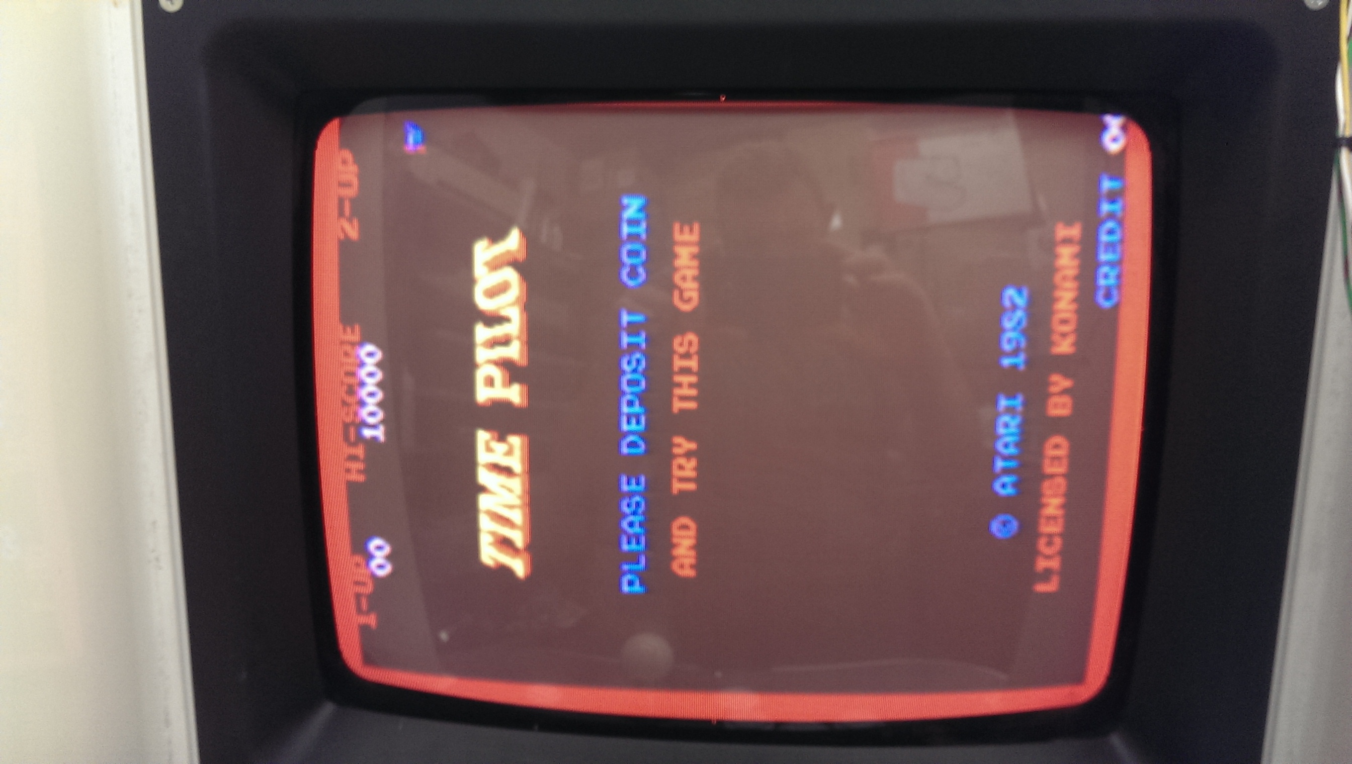
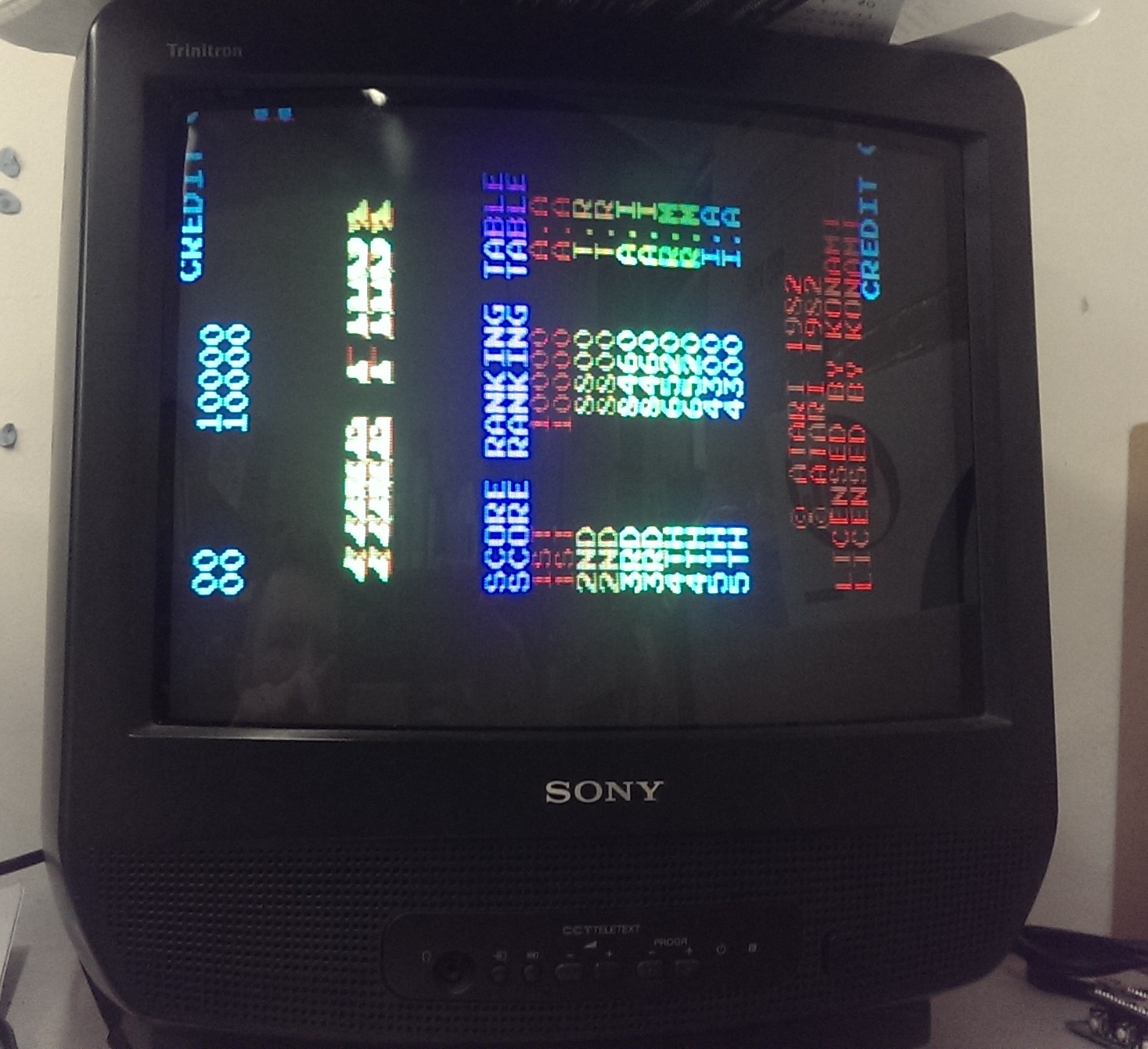
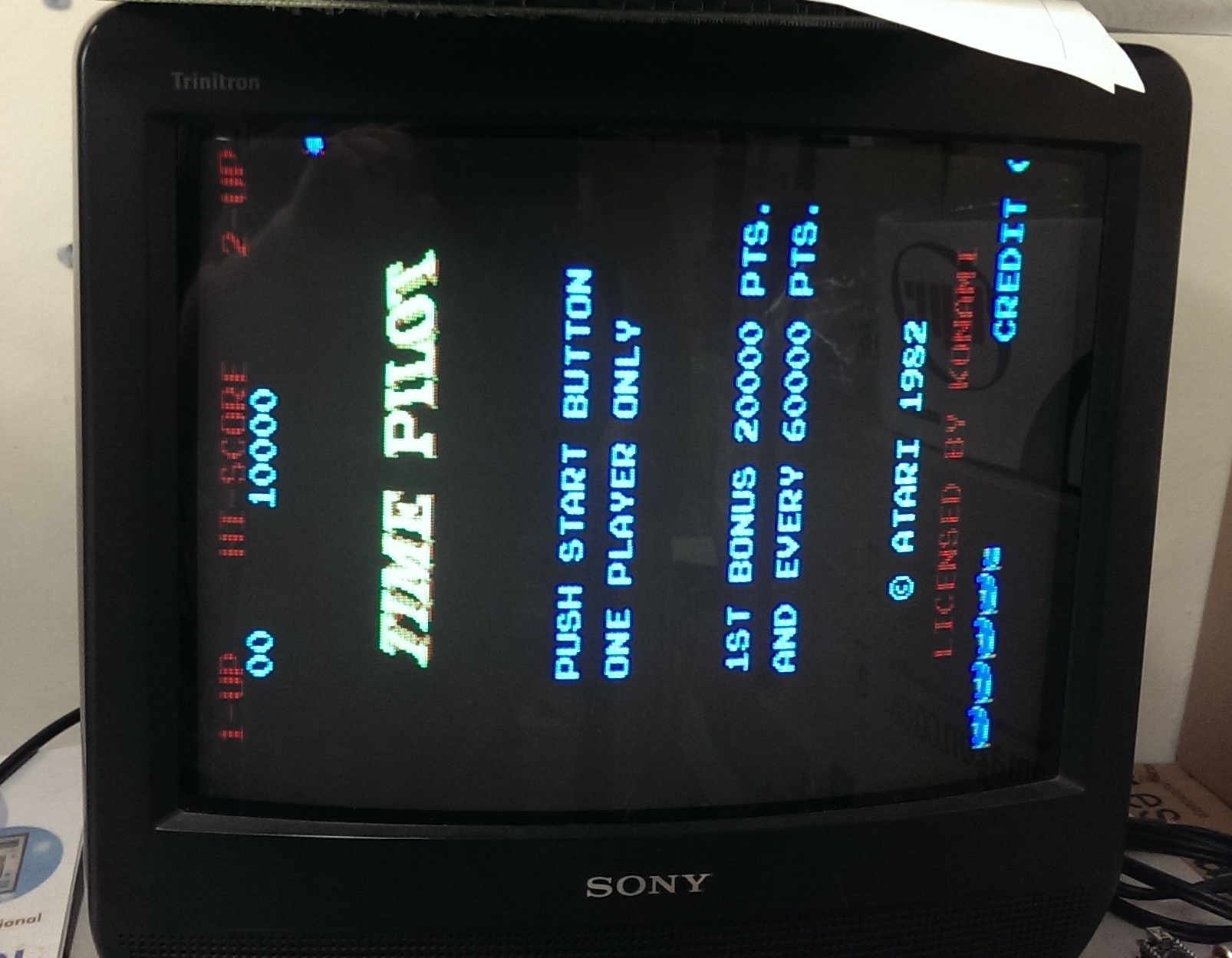
Straight away I ran into problems. I could not get this board to sync with any of the 3 screens I have on my test rig, it also wouldnt sync properly in my Astro City cab.
I have recently bought a couple of those mini cabs and one was stripped out at the time so I used the monitor from that and the board seemed to sync up just fine.
IMAG1396

There was that big red border around but I recall having the same thing on a Circus Charlie board I fixed so thought nothing of it.
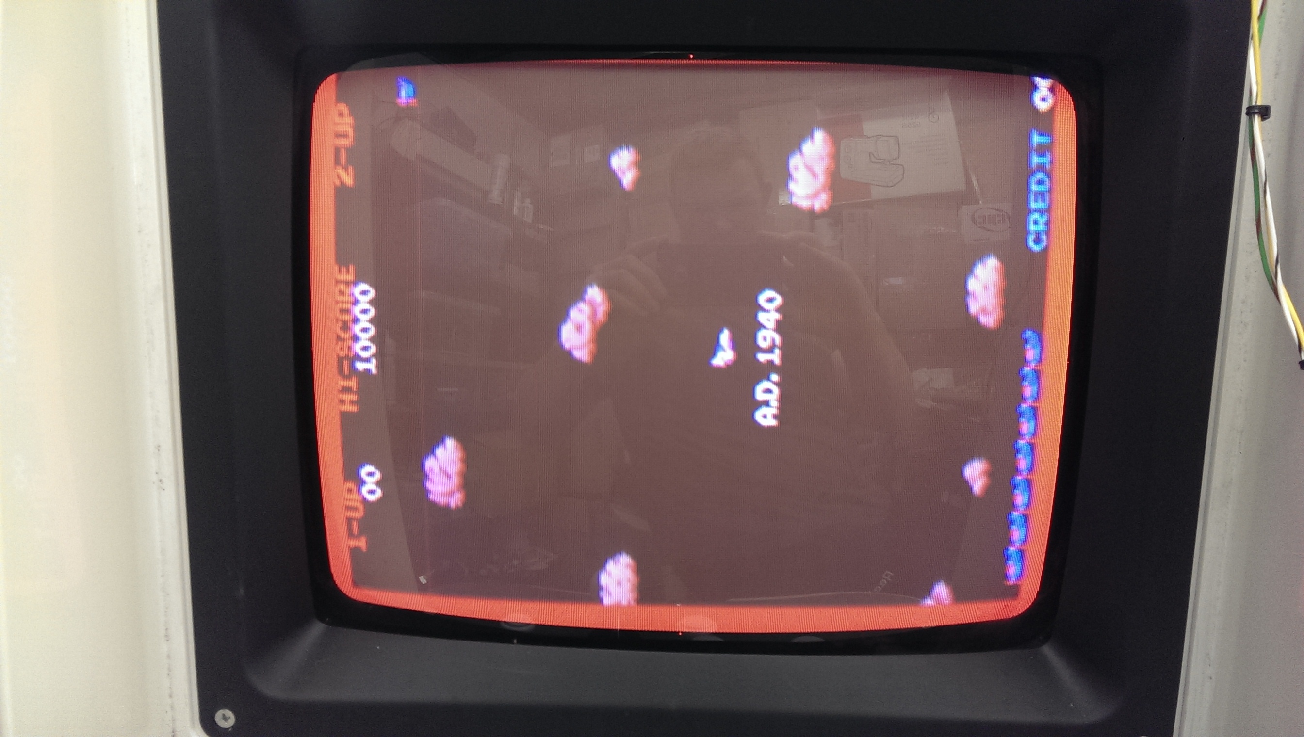
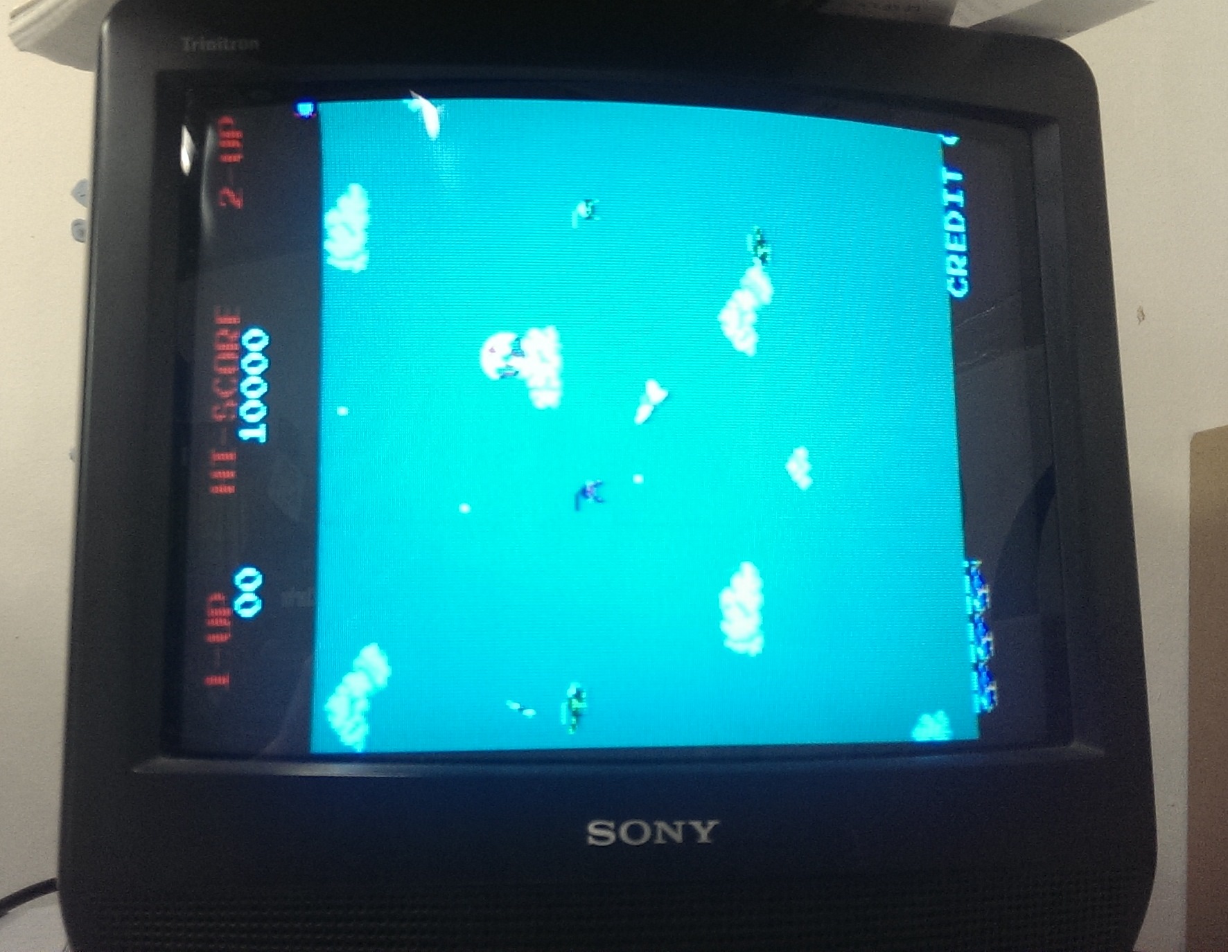
Playing the game led me to think the background colours were missing.
IMAG1399

I spent about 3 days going right through the schematics and running tests with the Fluke 9010 to figure out what was wrong. I couldn’t understand it. Muddy claimed that the background colours were present before he sent it off.

As I started doing more and more testing I started to get new faults with the sprites. I needed to figure out which chips were the sprite RAM’s so I reversed the ‘custom’ chip known as K526. In reality this chip is an 82s153. I dumped the chip and reversed it into equations

Pin 1 = MREQ
Pin 2 = RFSH
Pin 3 = A15
Pin 4 = A14
Pin 5 = A13
Pin 6 = A12
Pin 7 = A10
Pin 8 = F4

0xb400 (spriteram2)
/o12 = /MREQ & RFSH & A15 & /A14 & A13 & A12 & A10 & /F4

0xb000 (spriteram1)
/o13 = /MREQ & RFSH & A15 & /A14 & A13 & A12 & /A10 & /F4

0xa000 (main ram. covers color ram and video ram too)
/o14 = /MREQ & RFSH & A15 & /A14 & A13 & /A12 & /F4

0x8000 (Goes to pin 12 of 501 custom and also F3.)
/o15 = /MREQ & RFSH & A15

0x6000 (enable for unpopulated ROM socket, H5)
/o16 = /MREQ & RFSH & /A15 & A14 & A13

0x4000 (ROM H4)
/o17 = /MREQ & RFSH & /A15 & A14 & /A13

0x2000 (ROM H3)
/o18 = /MREQ & RFSH & /A15 & /A14 & A13

0x0 (ROM H2)
/o19 = /MREQ & RFSH & /A15 & /A14 & /A13

I figured out that the 4 x 2114 chips at D7 – D9 were the sprite RAM. 3 out of 4 had failed one by one so I ordered some up and replaced them when I got them.
All the sprites were back but still no background colours.
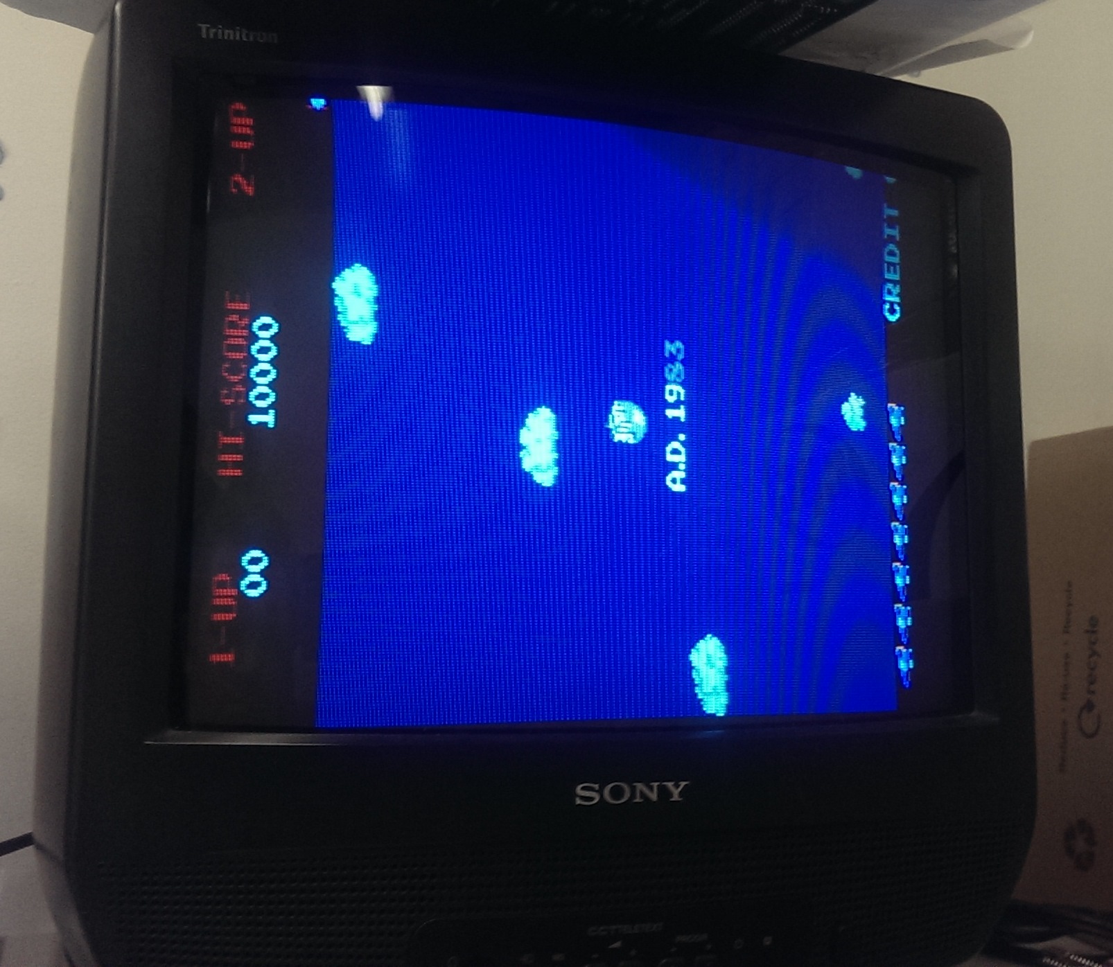
In a desperate attempt I wired the RGB-S straight into a scart connector to try a different TV. This is what I got.
IMAG1417

The backgrounds were there all along but for some reason my other monitor wouldnt display them. I know the monitor works fine with my other games but why I did this I have no idea. If anyone knows or has any theories I would love to hear why.

On with the repair.
As you may already know this board gave me the opportunity to test Shoestring’s diagnostic ROM. After a few teething problems we got it working and I was able to test the player inputs. To my surprise they all worked fine and testing in game confirmed this. No idea why it didnt work for Muddy but it works now.
After getting the game up and running with background I noticed the main ship sprite was no longer a ship (see picture above).
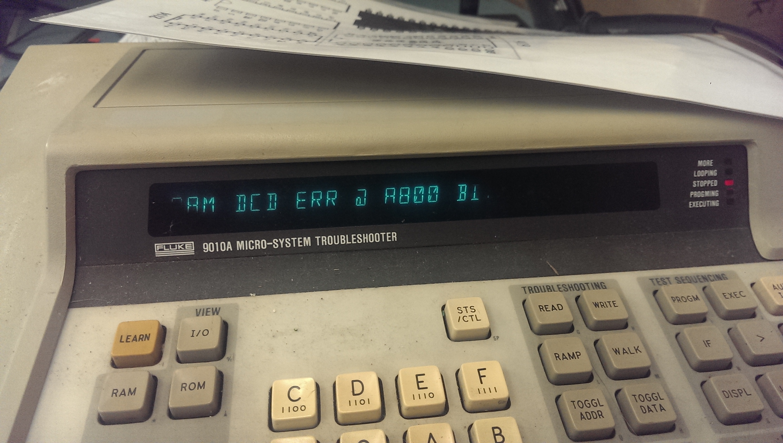
Lightly flexing the boards fixed the problem but then the board stopped working. The Fluke was already plugged in and running test gave me a DCD error.
IMAG1418

This error means there was a problem with the RAM addressing/decoding. This issue is normally missed by POST routines as they simply write a value to an address and read it back comparing it. The Fluke doesnt do this. It writes specific values to specific addresses so if there are any addressing issues it can tell. My issue ended up being caused by me. There was a tiny flake of loose solder bridging two address lines on the main RAM. Removing this made the game boot again but now I had another issue.
IMAG1423

The graphics were now doubled up.
This was easy to find and ended up being a dodgy socket on the 082 custom chip at location F5. I replaced the socket and now everything was good again.

With that all done it was on to the sound.
I was getting a little tired of looking at this board so after a few preliminary checks I just desoldered the Z80 and fitted the Fluke.
BUS CHECK showed bit 0 and bit 1 were stuck LOW. I wrote 0x55 to a point in RAM and read it back, I got 0x50.
I then wrote 0xAA to the same point and read it back, I got 0xA0.
Looking at the schematics I pinpointed the offending RAM chip to the 2114 at B7.
Replacing this game me back the sound.

On the final test the sprites died again!!
I replaced the last 2114 RAM chip on the main board and this is now 100%
IMAG1429

IMAG1426

 Posted by at 9:14 pm

Using the HxC Floppy Emulator with a Fluke 9100

 Guides  Comments Off on Using the HxC Floppy Emulator with a Fluke 9100
Jul 192015
 

Recently the floppy drive on my Fluke 9100 became unusable and I feared the worst. I’ve tried once before to get the HxC floppy drive emulator to work with this but I never managed and to be honest I’ve never delved into floppy drives at all so I was a bit clueless.

I found THIS site while looking for information and at first I skimmed over the details and didn’t really take any of it in. That was a big mistake as it provided all the information I needed to get this up and running.

The only thing I needed to do on the hardware side of things was to cut pin 14 of the floppy cable and connect the Fluke 9100 side to GND.
Everything else is all software.
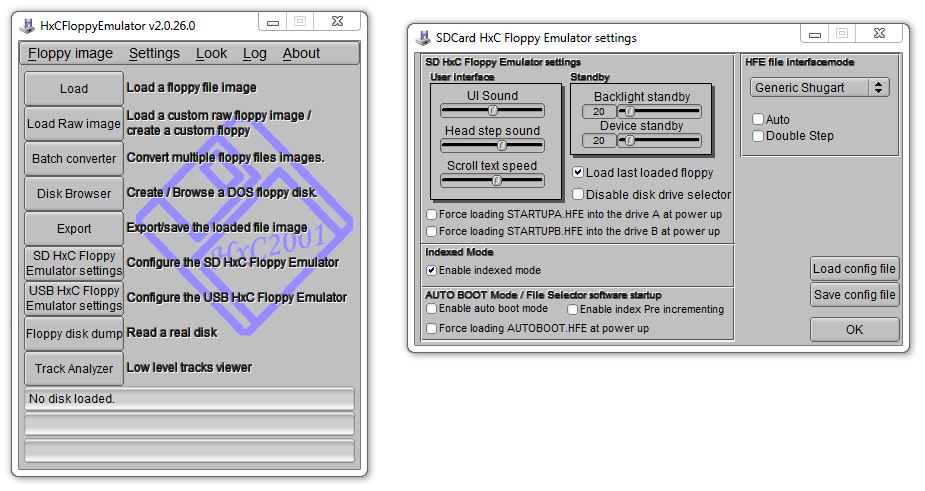
In the HxC Floppy Emulator software you need to apply these settings
settings

Save the config file to the SD card.

Then “Load” the .TD0 files that are available from HERE or HERE.

The HxC software can deal with these files without any issue so once you have loaded one go ahead and “Export” it to your SD card using the indexing naming scheme
Disk 1 = DSKA0000.HFE
Disk 2 = DSKA0001.HFE
etc

I have the first dip set to ON on the HxC device.
Once that’s all done you can fire up the Fluke and use your SD card to load.
My Fluke doesn’t have an SCSI controller hence it has no hard drive fitted so it is vital I have a working floppy drive.

Once you have the OS loaded up from the floppy drive you may need to change the way the system loads the user disks.
If your system is configured to be a 9100 then user disks are defaulted to load from the hard disk.
If your system is configured to be a 9105 the user disks are attempted to be loaded from the second floppy disk drive.

The HxC floppy replacement can apparently be configured to emulate two drives but I cannot for the life of me get it to work so this is necessary for me.

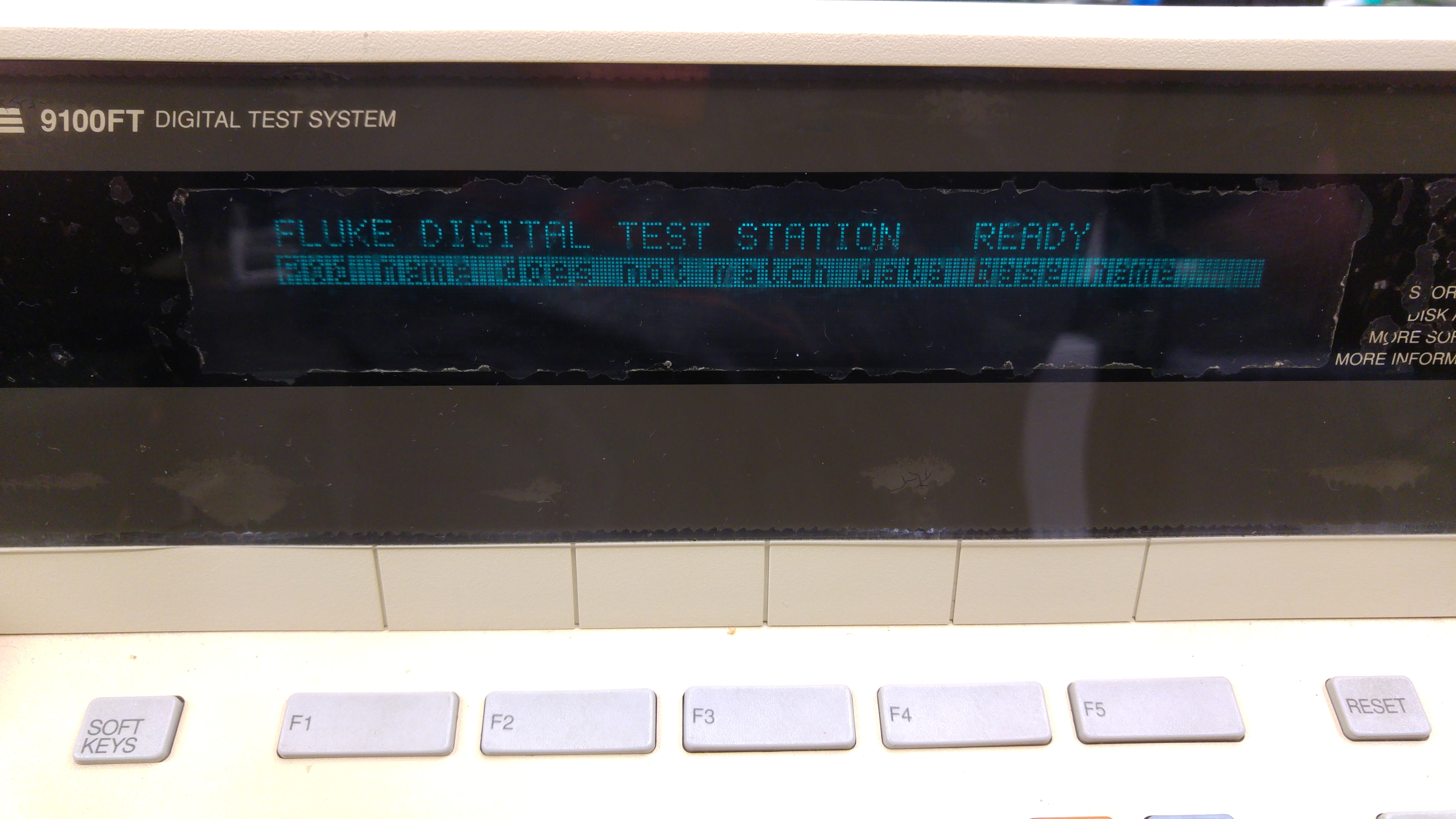
When loaded you will be met with this message
20160309_195246

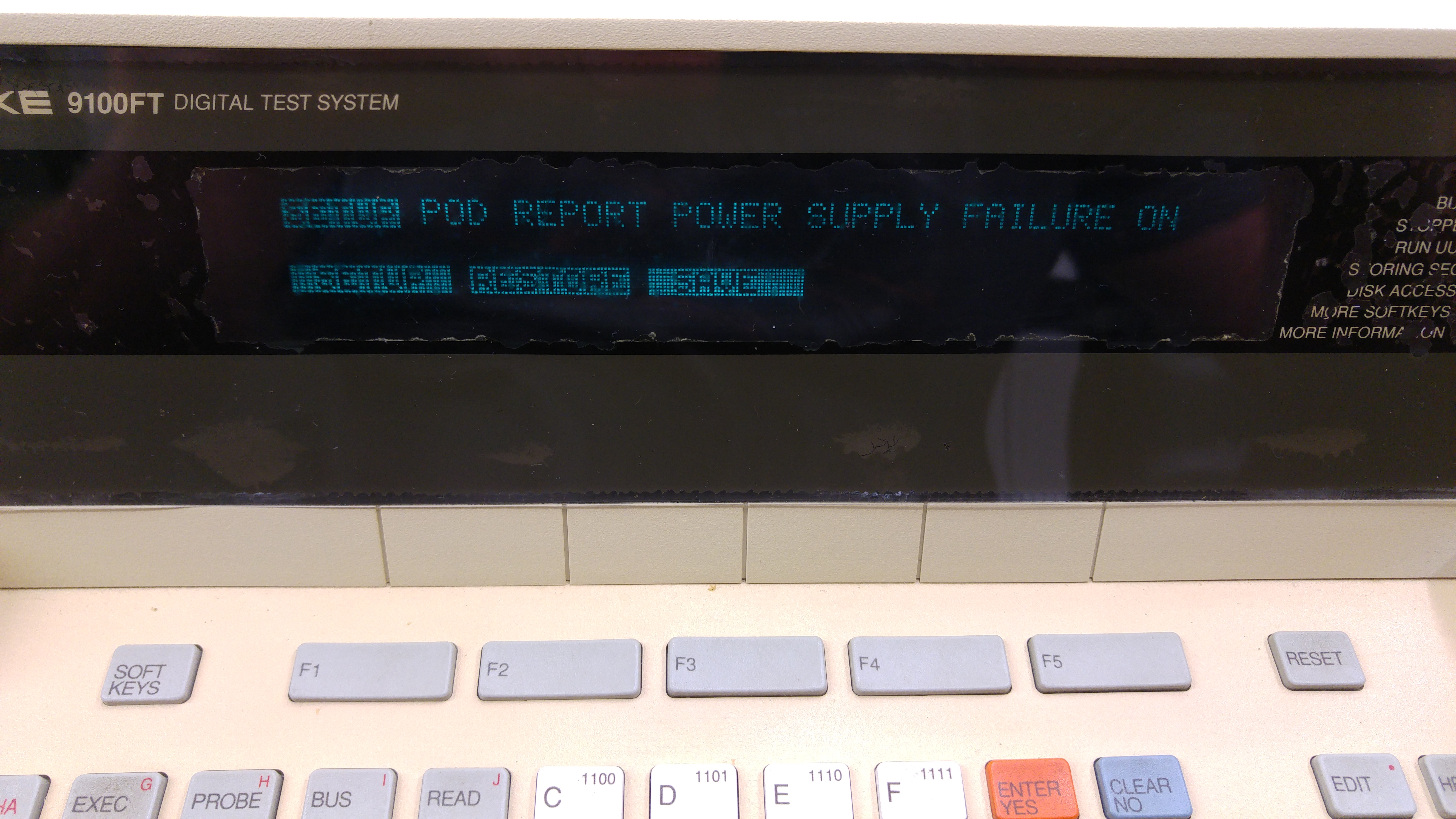
Press the ‘SETUP’ button
20160309_195256

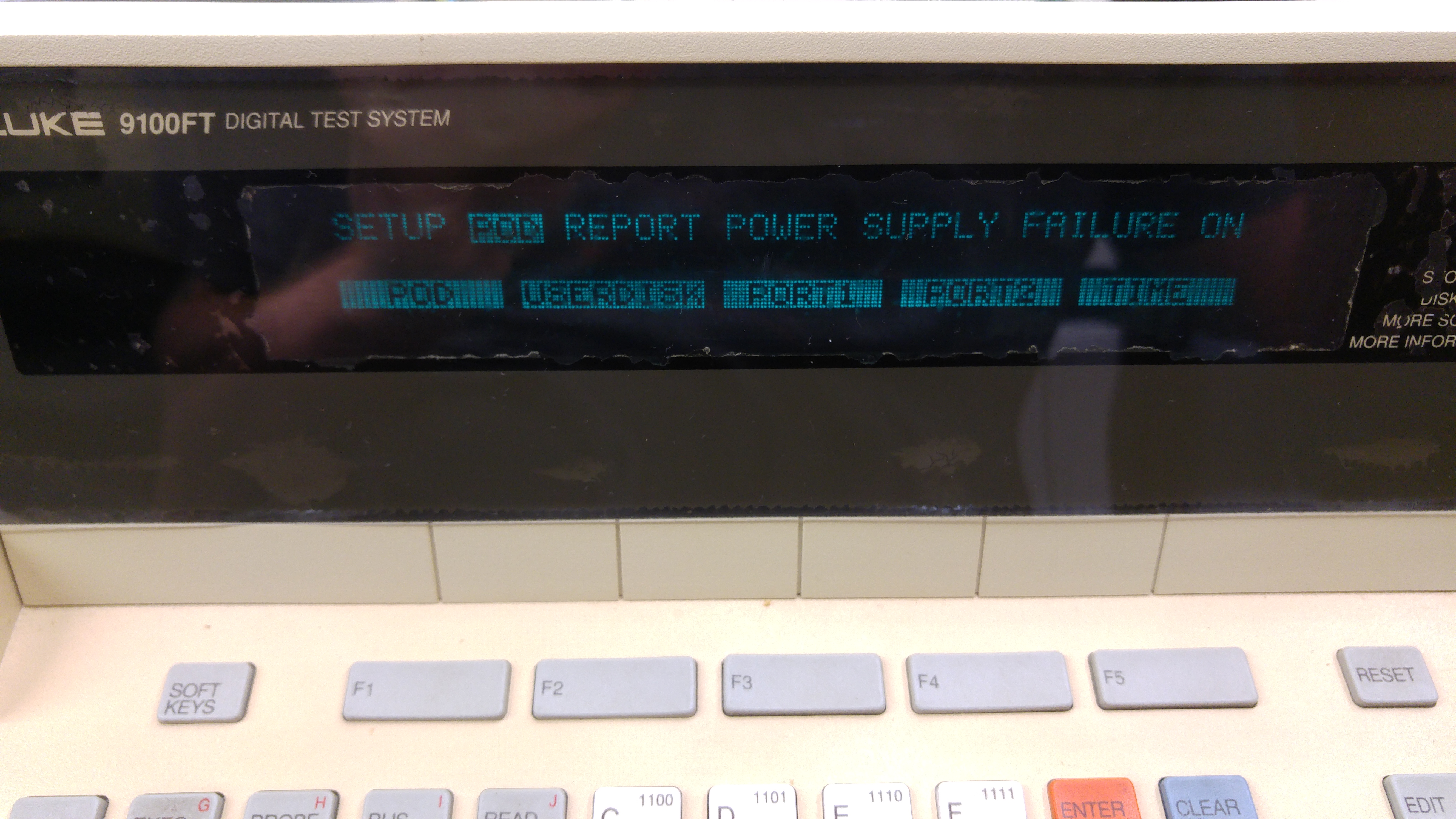
Move RIGHT to highlight ‘POD’
20160309_195304

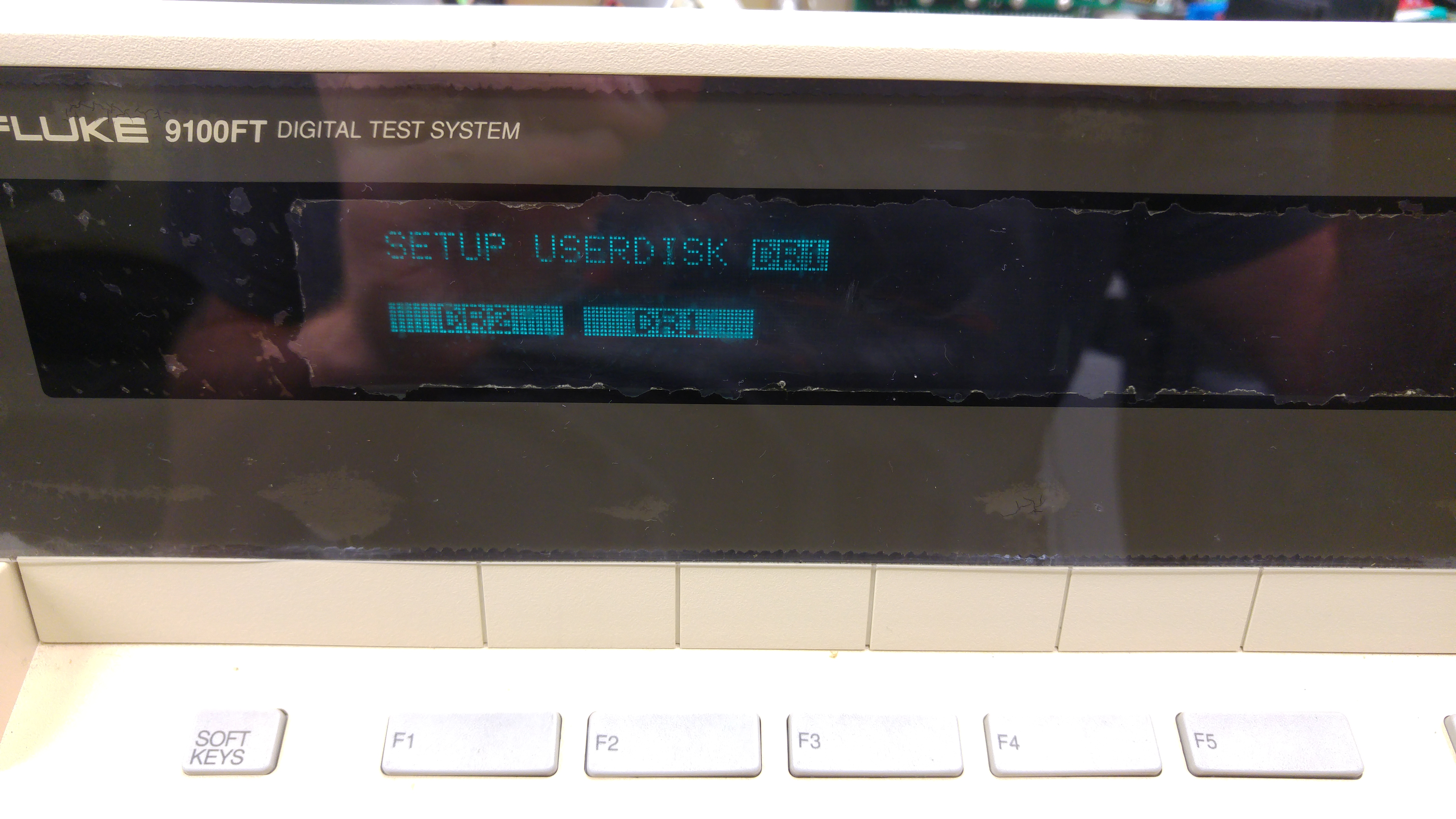
Press F2 (‘USERDISK’) then select ‘DR1’. This is the first floppy drive.
20160309_195319

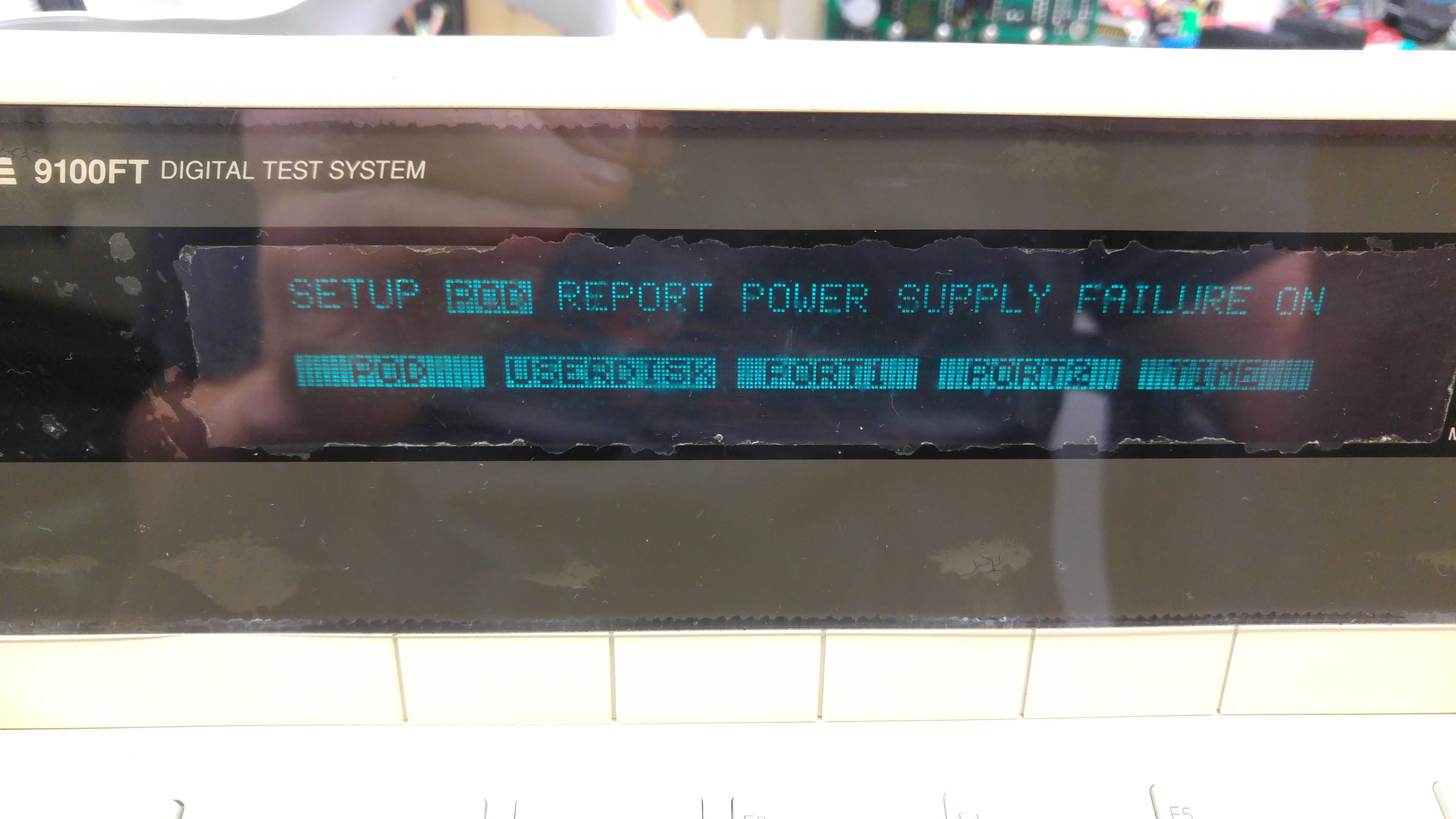
Go back to the initial ‘SETUP’ menu and select ‘POD’ again
20160309_195344

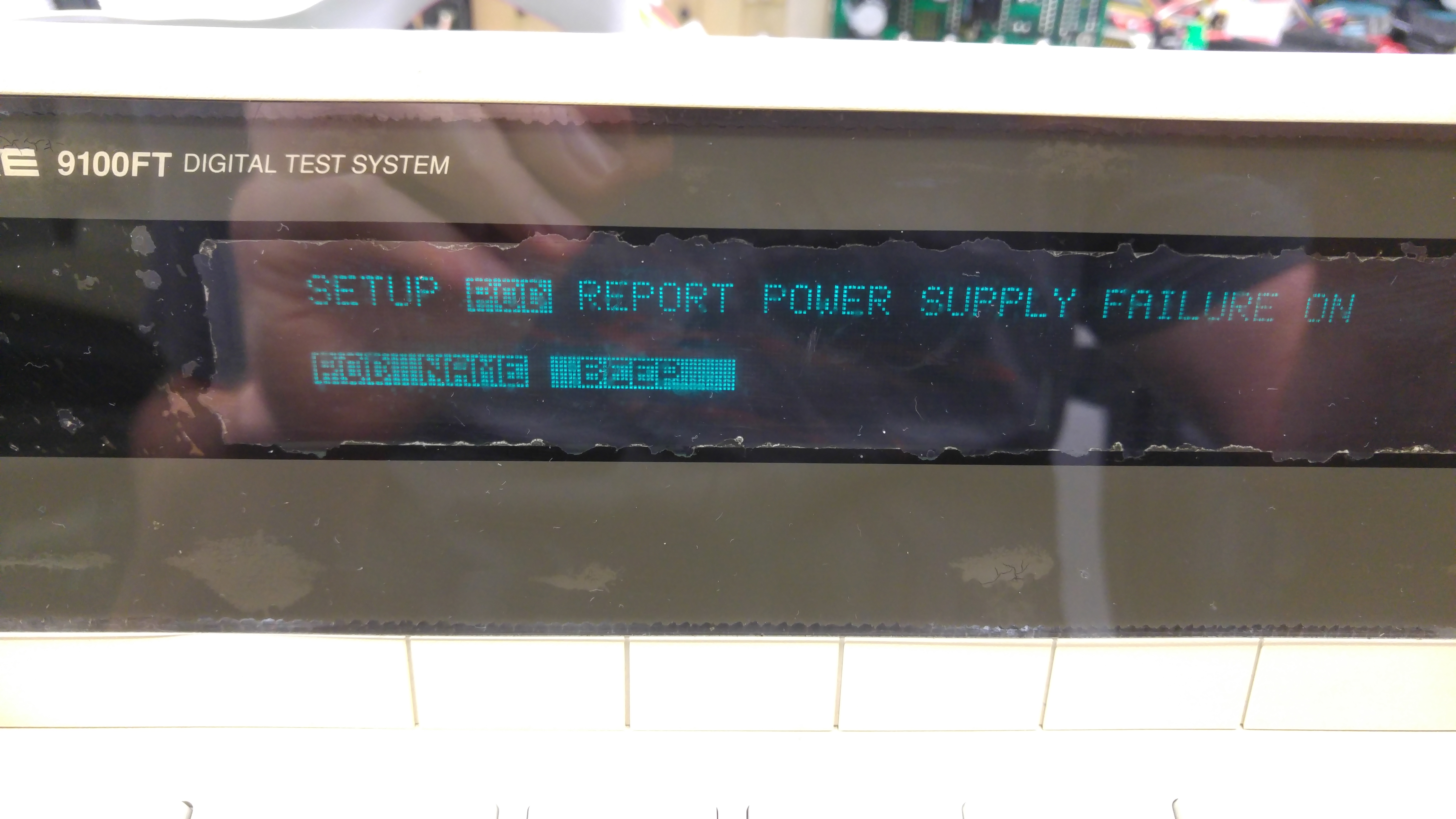
Then press the ‘SOFT KEYS’ button and some more options will appear
20160309_195349

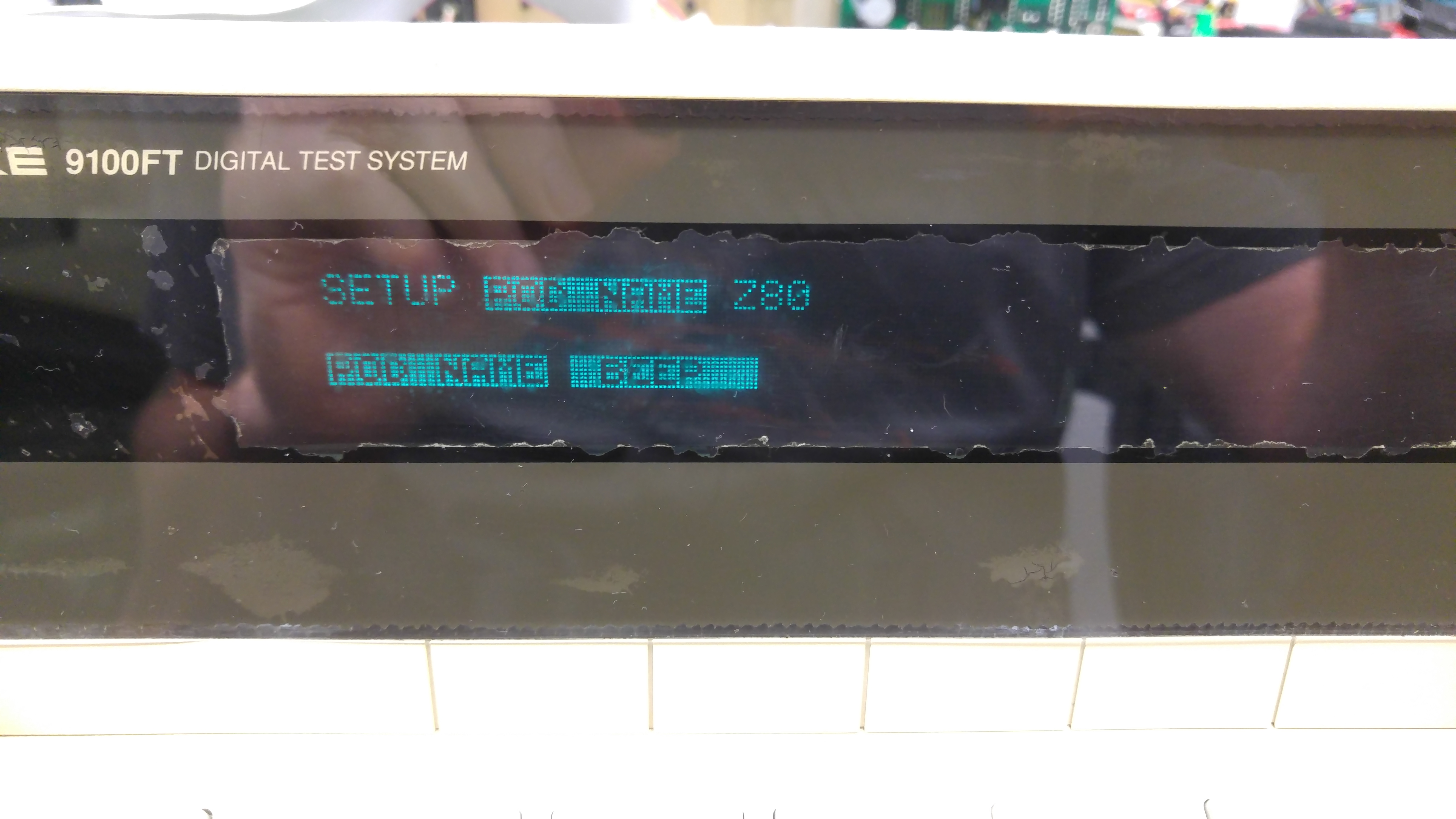
Select ‘PODNAME’ and you will get this (Z80 pod is used here)
20160309_195354

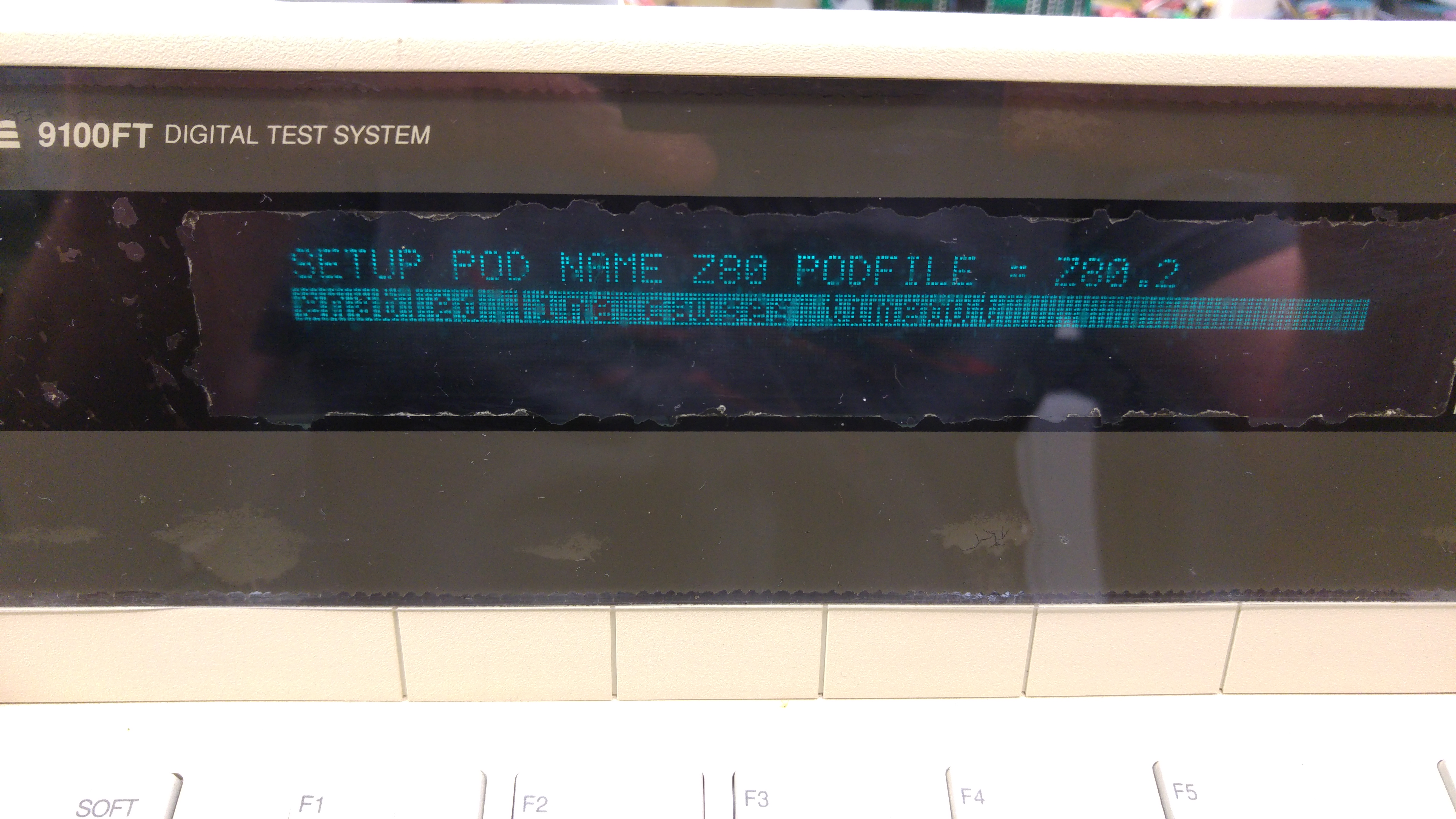
Make sure you have the correct disk image selected on the HxC then press the ‘ENTER/YES’ key.
If all goes well the floppy will read and you will be presented with a new message (its different depending on POD type fitted)
20160309_195459

Now the POD is available to use.
NOTE: If you press the ‘RESET’ button on the keypad at anytime then it will revert back to DR2.