Dumped 4x AT22V10 chips today of my Spectral Vs Generation PCB.
All the chips were unlocked. They may need converted to GAL22V10 format if that is your target device, i’m unsure whether the two formats are interchangeable.
Tecmo Knight repair log #2
Dug this board out today with the view of selling it.
I put it on to test and also fired up MAME for a comparison and noticed that the digital samples weren’t playing at all. It first noticeable on the attract sequence when the lightning strike and you should be able to hear thunder.
This game uses an M6295 chip in order to deal with the samples so it was really easy to make a start trouble shooting. Using the scope I could see all the inputs and outputs were toggling when I would expect and could see one of the enable lines going active when the thunder sample was meant to play but the DAO pin (pin 36) was just dead. I did try to reflow this just in case but it made no difference.
I replaced this with one from a scrap PCB
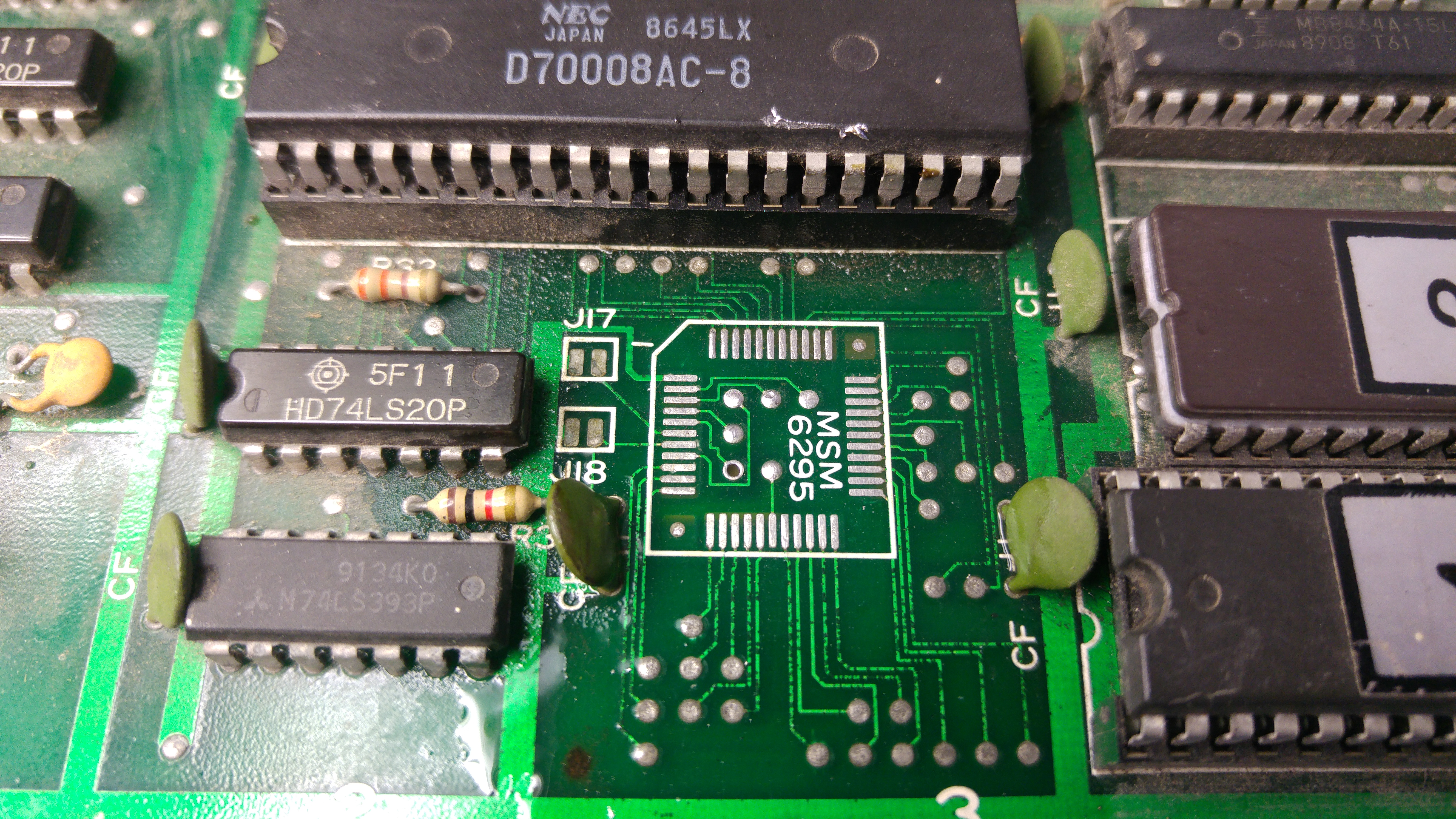
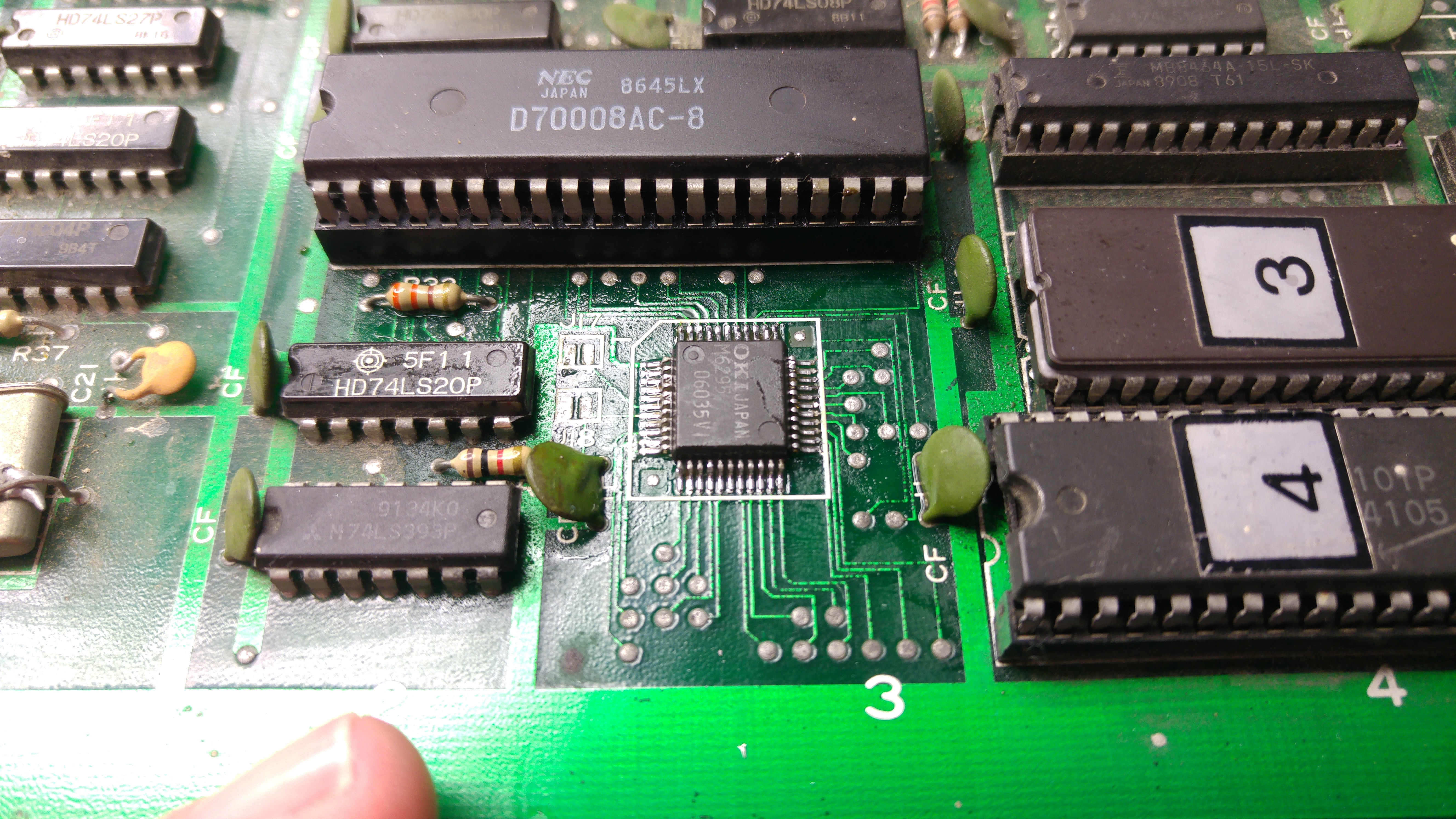
Sounds are all back now
Rainbow Islands – Clock Circuits
A short simple post on two of the clock circuits used on Rainbow Islands.
There are 3 x crystal oscillators on the Rainbow Islands PCB. This post will cover two of them. The third is used for selecting a chip enable line of some RAM in an elaborate way which I don’t fully understand right now.
First lets look at the X2 Oscillator which is 12MHz.
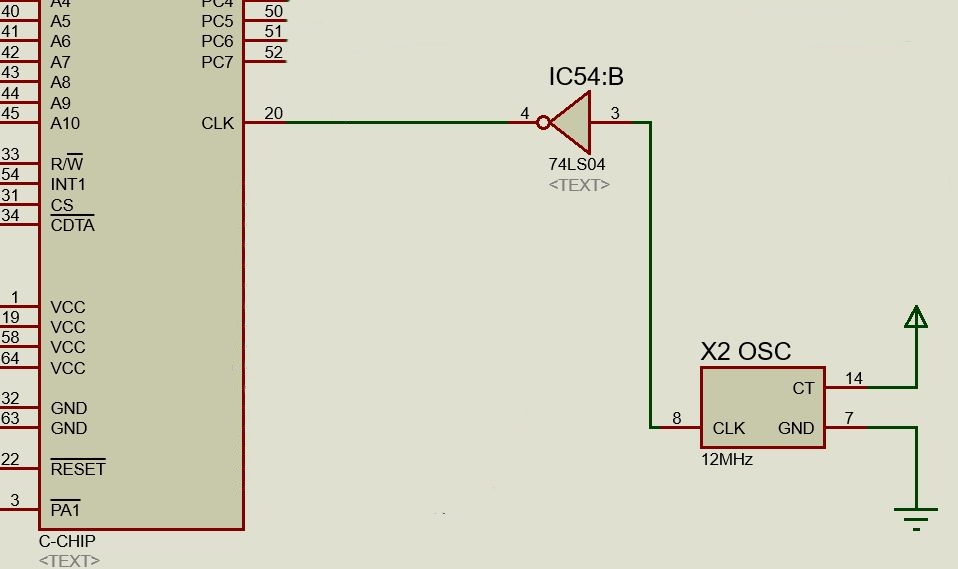
This is solely used as the clock for the C-Chip and simply goes though IC54, an inverter, into pin 20 of the C-Chip at 12Mhz. Easy!
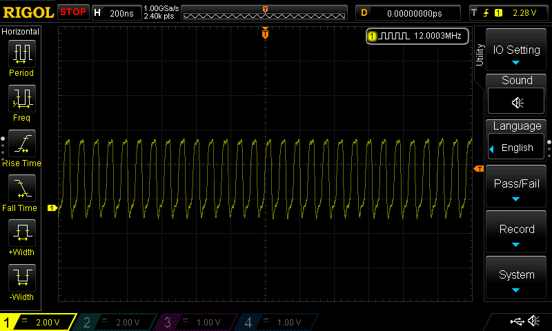
Next up is X1. This supplies the clock signals for the Z80 and the 68000.
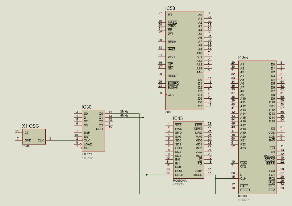
The 16MHz clock signal serves as the clock signal for a 4-bit binary counter at IC30. Output Q1 (pin 13) of this binary counter gives a 4MHz clock which is the clock signal for the Z80 sound CPU.
Output Q0 (pin 14) of this binary counter gives out the 8MHz clock for the main 68000 CPU.
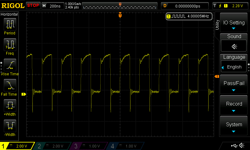
Both of these clocks also feed into the custom PC060HA chip at IC45 on pin 14 (SCLK) and on pin 15 (MCLK).
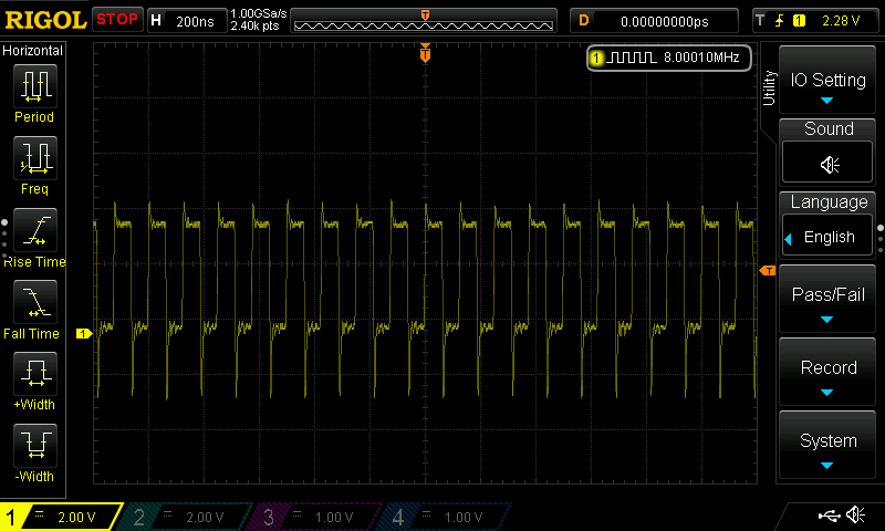
That’s all there is to this one.
Nintendo Helifire repair log
Got Muddymusic’s Helifire (not to be confused with Hellfire by Toaplan) to look at.
He bought the original cocktail cab and on first power up was met with nothing but a “loud noise”.
His initial checks were that his +5v line was reading +2.5v and sent me the PSU to work on.
Now due to the various AC voltages required to actually use the PSU I was unable to do any real testing so instead he sent me the transformer and PCB too.
Now I could start checking the PSU I found that the +5v line was indeed around +2.5v. While I had the PSU powered up I suddenly got a +5v voltage output and it was pretty solid.
I couldn’t check to see if the game was running at this point as I had no way to connect the game to a monitor so I probed the video out pins with the scope and everything appeared to be at least what I expected.
While I had the PCB hooked up to load the PSU I momentarily saw the voltage on the +5v line would drop to +2.5v and then to my horror rose up to +8v!
I immediately powered it down and it has not been back on since.
I opted to hook it up to a switcher but when I did I noticed the video sync output was missing. I guess the PSU took it out. I also noticed the 8080 CPU wasn’t running either and was getting quite hot.
I’ve got access to a thermal camera right now so checking the PCB with that revealed the 8080 in the top right corner was way too hot.
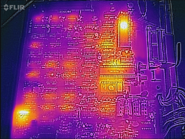
I had no spare 8080 CPU’s so placed an order for a couple and moved onto the missing SYNC signal.
Working backwards from the SYNC output and using the schematics available I quickly found the 74LS109 at location 3B had stuck outputs despite having good inputs and a healthy clock signal.

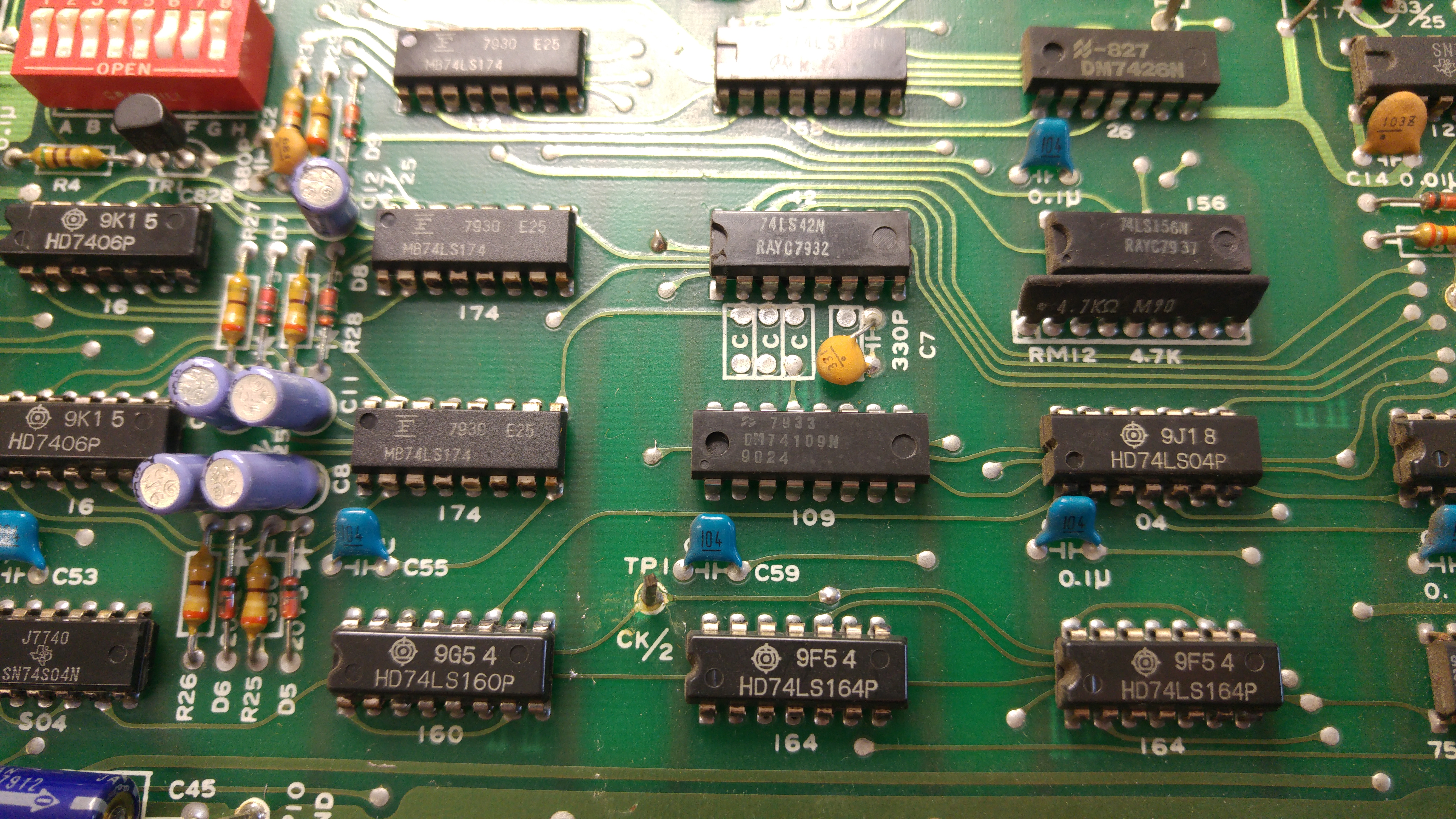
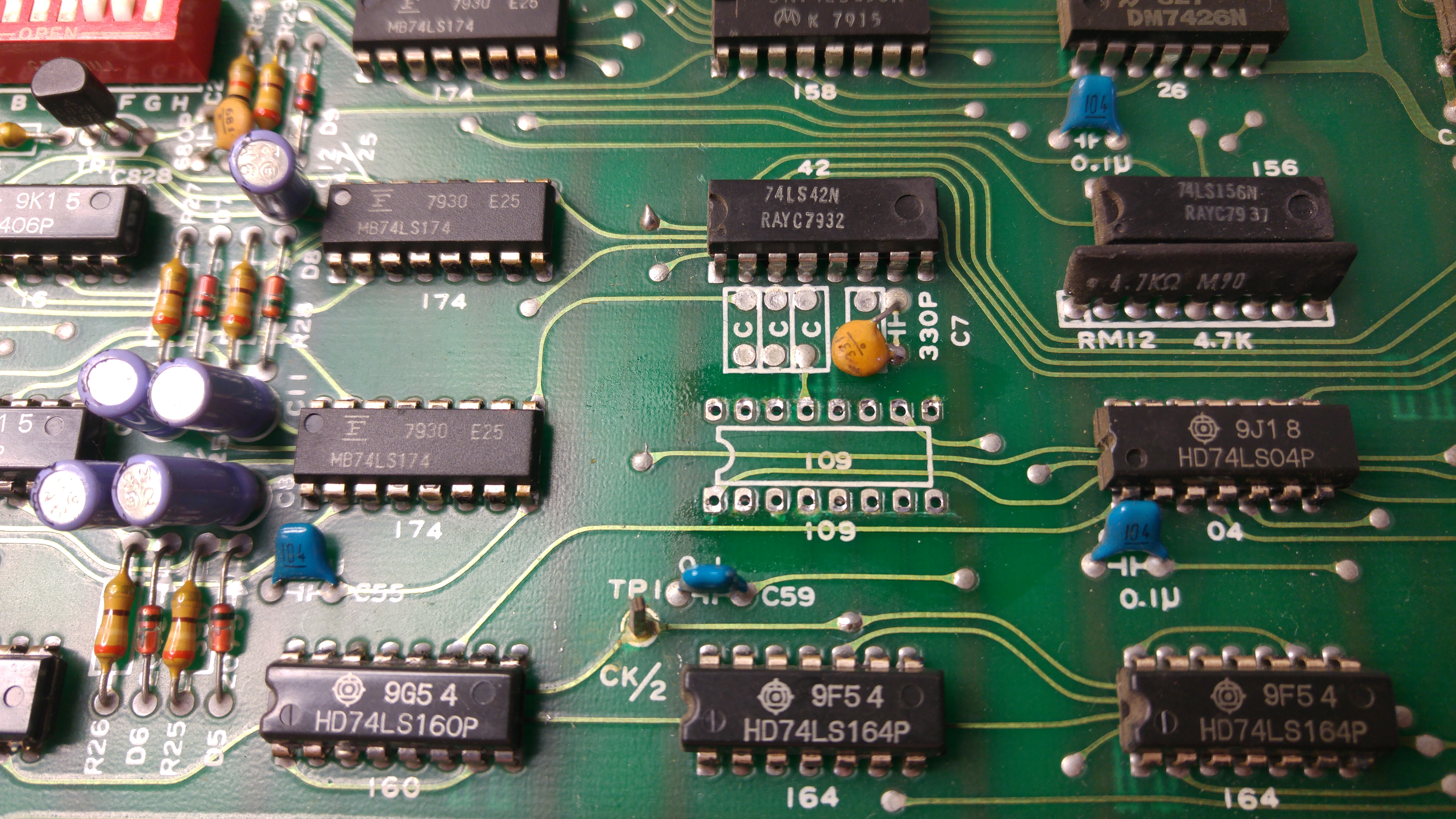
Replacing this chip gave me back my signals.
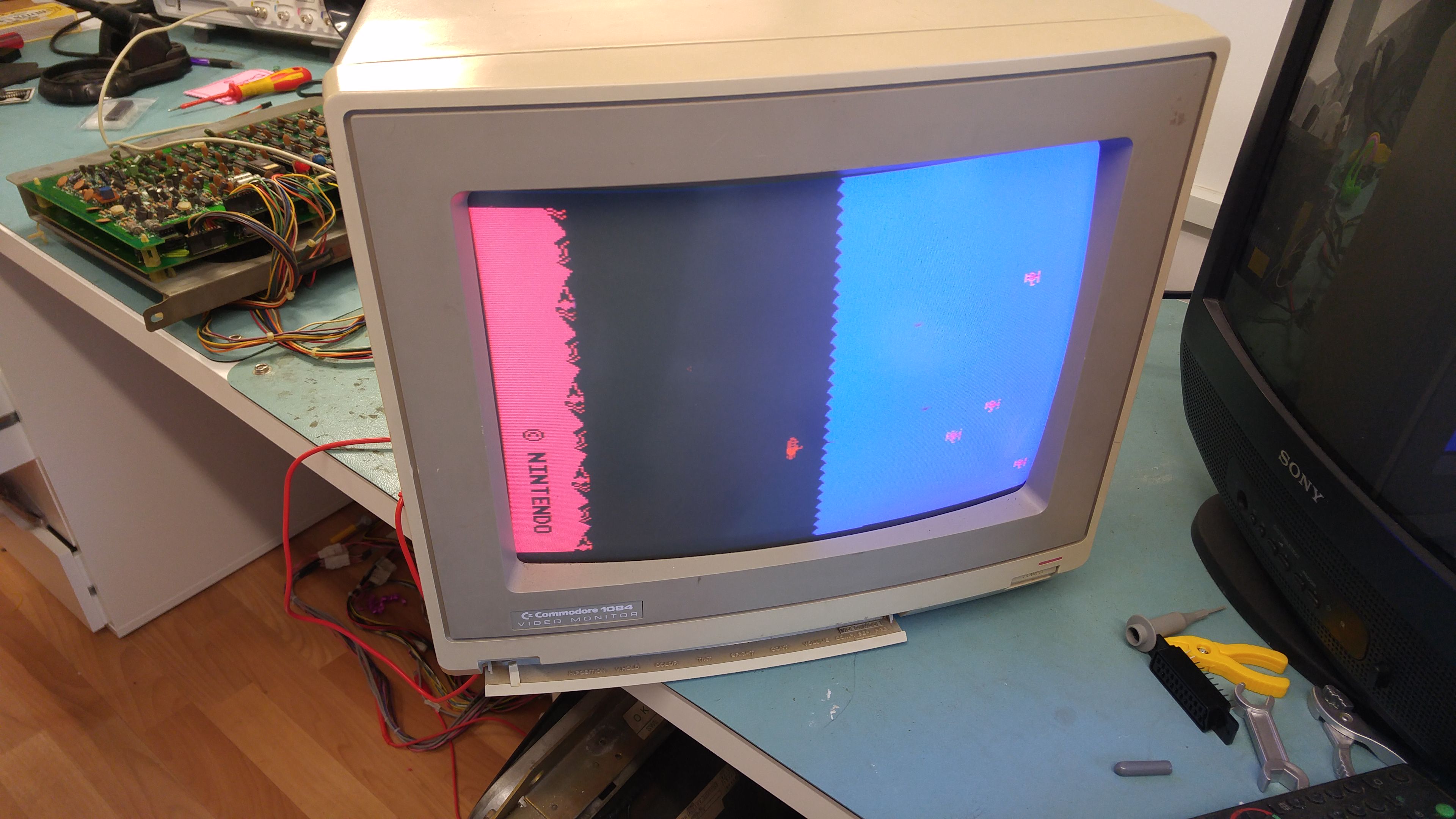
A week later my 8080 CPU’s arrived and I managed to get the video output hooked up to my Commodore 1084D monitor to test.
At the time I didn’t even realise that the game was black and white and uses a colour overlay so I was initially confused by the colour in the game but Muddymusic soon put me right on that.
Bit manipulation added to BINman
Philmurr from the UKVAC forums was asking about a program to manipulate the bit order for address and data lines of a ROM dump.
I had the idea for manipulating data lines in the past when I was dumping the Arcadia ROM’s from Unigame but I never followed through with it until now.
Anyway I have now added support for this to my BINman program.
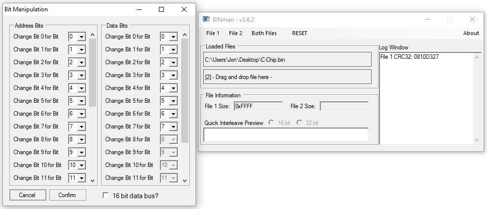
Its fairly self explanatory I think and it has been tested by Philmurr on his Scramble ROM’s and I did some testing with Arcadia ROM’s too.
Latest version is 3.6.2
