Using a lightgun with Operation Wolf PCB

 Guides  Comments Off on Using a lightgun with Operation Wolf PCB
Apr 052016
 

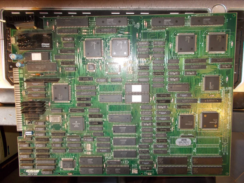
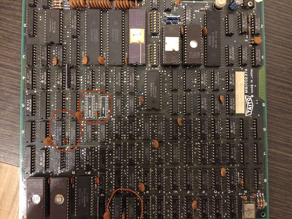
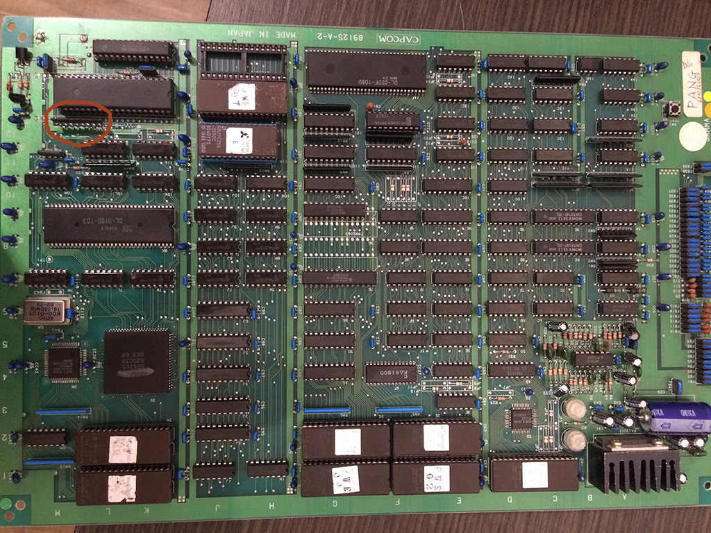
Some days ago I received an Operation Wolf PCB bought from Hungary.After dumped ROMs and comparing the board layout with pictures on the web it turned out to be a rare prototype which runs unprotected code (it lacks of the C-CHIP IC).I suggest you to read the whole story on David ‘Haze Haywood ‘ homepage:

A Wolf in Prototype Clothing

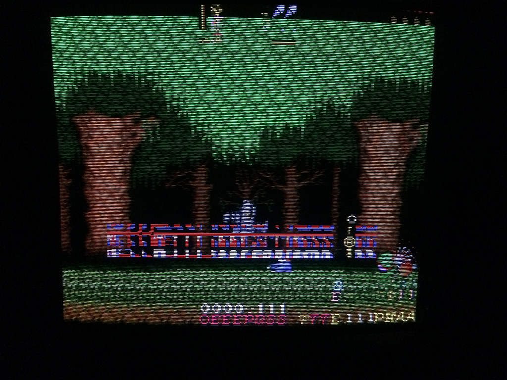
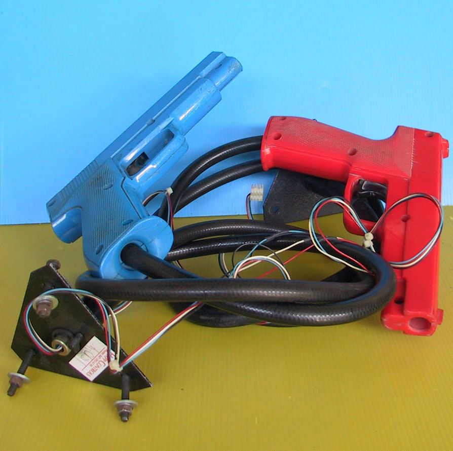
After adapting the board to JAMMA, I fired it up and it was perfectly working.Reading on the Web,  there are conflicting opinions if this board is a simpe lightgun game or it uses analog joystick like some many people claim.So I wanted to try myself and bought a couple of cheap Happ lightguns widely used on games like Lethal Enforcers :

happ_gun

All lightguns work in the same way: you’re pointing your gun at the screen, and the gun is essentially a light sensor.When the part of the screen which the gun is pointing at gets flooded in white, the sensor detects it and sends a signal to the game: “I can see white now, I’m pointing at the part of the screen you’ve just drawn”. At this point the game can work out how far down the screen it has drawn, and how far along the current line, which gives a pretty accurate position of where the gun is pointing.

The Happ gun has a 4 PIN connector and looking at Lethal Enforcers schematics, this is the pinout:

happ_gun_connector

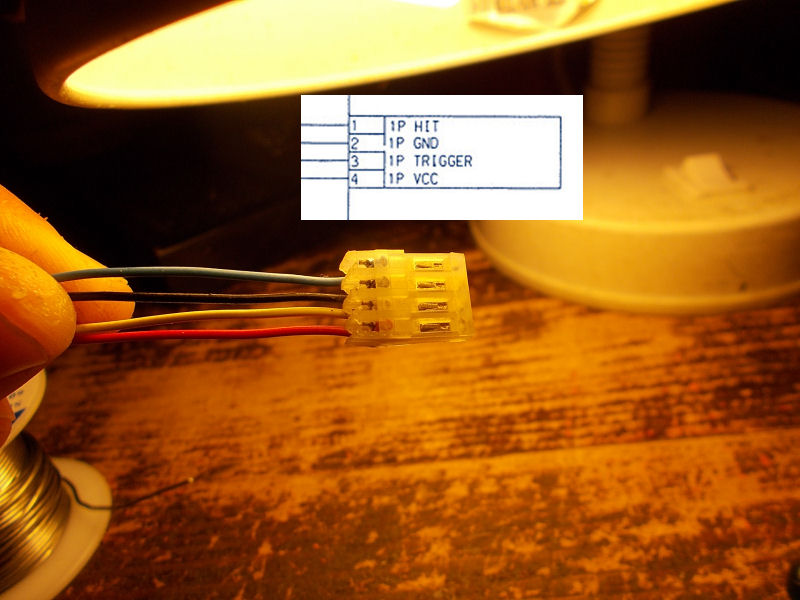
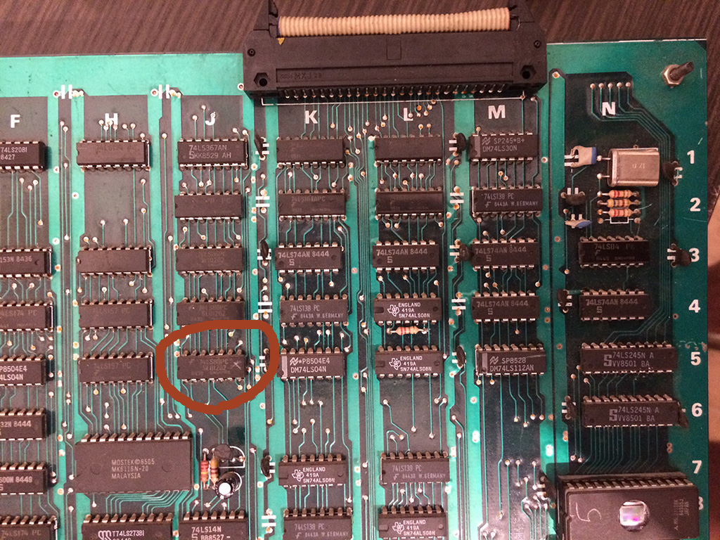
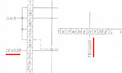
The ‘HIT’ signal (so called in Lethal Enforcers but name is relative) is an input on arcade PCBs and it’s essentially the output of the optical sensor (a phototransistor) mounted inside the gun.The ‘TRIGGER’ is the switch inside the gun and it’s shorted to GND everytime, indeed, you pull the trigger.VCC and GND are obviously needed to power the electronics inside the gun.With this info it was very simple to adapt this gun to the Operation Wolf PCB.The pinout of this board shows ‘TRIGGER’ signal on pin 21 parst side of ‘G’ edge connector on main board and ‘HIT’ (called ‘SENSOR’ in service manual) on pin 5 solder side of the ‘T’ edge connector on sound board:

SENSOR_TRRIGGER

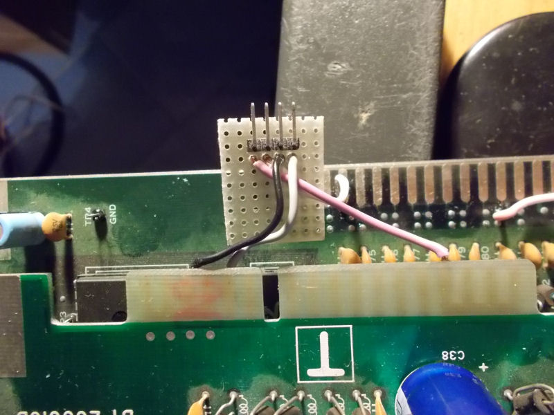
For a better interfacing of the gun to the PCB I used a 4 pin right-angle male header mounted on a piece of veroboard:

4_pin_header_Operation_Wolf

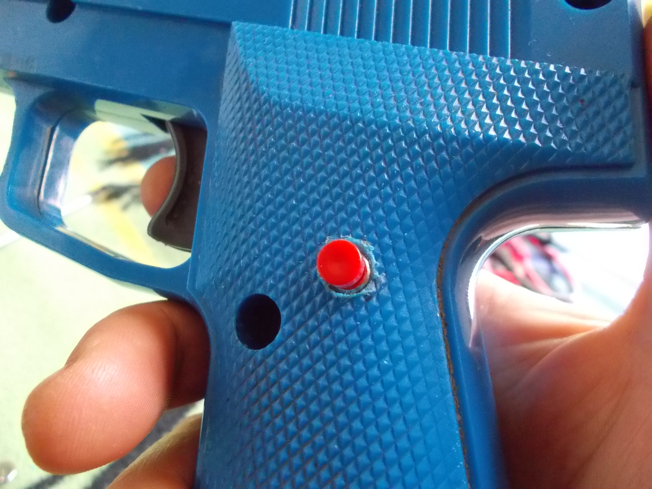
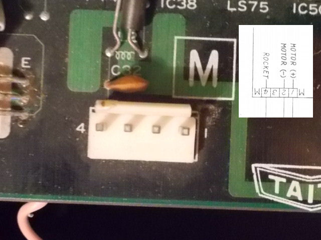
Lastly, since Operation Wolf use another input for rocket and this Happ gun lack of a second switch, I added a further button (a normally-open one)  mounted inside the gun and connected to internal common GND and ‘ROCKET’ signal which is PIN 4 of the ‘M’ connector on Operation Wolf main board (but if you want, you can also adapt a PSX/Saturn Guncon which comes with more than a button)

rocket_switch


M_connector_pinout

Finally now for sure I can say that Operation Wolf is a simple lightgun game.So let’s go to play it!

 Posted by at 11:33 pm

Gaiapolis repair log

 PCB Repair Logs  Comments Off on Gaiapolis repair log
Apr 052016
 

Some days ago I received this Konami Gaiapolis PCB for a repair:

Gaiapolis_PCB

It showed a graphical issue where some background layers were missing but pressing down the PCB they came again although in wrong place:

issue

Hardware uses some custom ASICs to generate the various parts of graphics so I made a reflow of the two involved in tiles but this didn’t fix the issue.Using some dummy ROM files in MAME for the backgrounds data I noticed the missing/misplaced graphics were not affected so they were not really backgrounds.The board is capable also to rotate and zoom objects (‘ROZ’) and the ASIC which performs this function is the ‘053936’ :

053936

So I went to inspect it and found this:

053936_touching_pins

Two pins (connected to data lines of two 6264 RAMs) were touching each other and the rightmost one lost contact with its pad.I restored the proper connections and graphics came back in right place:

fixed

I was declaring the board 100% fixed but I noticed some palette/priority issue :

palette_issue

The ASIC involved in this function (it can do other GFX tricks like alpha-blending) is the ‘055555’:

055555

A simple reflow of it was enough to fix the board completely.

palette_issue_fixed

 Posted by at 8:55 pm

Super Qix repair log

 General, PCB Repair Logs  Comments Off on Super Qix repair log
Apr 052016
 

Got this game for a repair.

The pcb was missing one program rom and a graphic rom.

After checking which version was the game, I burned the correct eproms and I got this screen:

sqix1


A ram was reported bad but I didn’t know which one.

There were 2x 6116 SRAMS and 6x DRAMS type 4464.

When the error message is shown, the game get stuck in a loop and continuously checks the status, therefore I discovered that shorting pins of the DRAM @9L and 9M changed the hexadecimal value of the error.

With a logic probe the signals were oscillating but I decided to desolder them and put some sockets and test other drams I had to see if the problem changed or better could be solved.

Please note that all the DRAMS I had were taken from dead boards and I had no way to test them out of circuit.

So I proceeded to place the sockets and installed some drams chip and I got always different bits until finally it passed the POST test!

sqix2


Turned out that I had several defective DRAMS chips and I took the chance to use Super Qix as a DRAM tester 🙂

Below are a collection of defective DRAMS, as you can see they are all from different brands…

sqix4


Back to Super Qix, , after changing the DRAMS, the game passed all the tests without further errors but I got this:

sqix3


The game had still the gfx messed heavily even if the ram test was reported good.

I shorted two pins of DRAMS @6S and 6R and I could see some better picture beneath the mess, so I decided to change also those two drams

I started the game board without them in place and I got this:

sqix5


It was a good sign but to be 100% sure there were faulty I placed them back on the sockets @9L and 9M and I got again the error on the post screen!

After placing two good drams I got this:

sqix7


Decided to go straight to the next two drams @5P and 5M and replaced without any further thoughts and…..

sqix8


Problem 100% fixed! Game had no further problems

So turned out that the game had all the 6 drams faulty but the game checks only 2 Drams out of 6x.

The other checks are done on the color sram and program sram.

sqix6

Pang repair log #4

 PCB Repair Logs, Repair Logs  Comments Off on Pang repair log #4
Apr 042016
 

9 years ago I got a Pang for my personal collection. It was still with original battery and I carefully changed it with a new one because I didn’t like the wire wrap mod to desuicide it.

Unfortunately 1 year ago while testing the kabuki desuicider the game didn’t boot anymore, steady blue screen.

After testing succesfully the kabuki desuicider on another board it was clear my Pang developed a problem.

For more than a year I never managed to repair it until I got a Fluke 9010A which showed a problem on the z80 bus, the READ signal was not driveable.

I immeditely noticed that it had a very low resistance to gnd.

Near the Z80 there is a resistor network 4,7kohm.  the read signal was connected to a pin of this network which had only a resistance of 427ohm.

pang

I decided to desolder it and install a new one but the game didn’t boot.

I decided to let the game rest for some more time until one day I discovered that the game sometime booted , sometimes not but when it booted it crashed soon after.

Upon closer inspection I discovered that I soldered very loosy a pin of the network resistance!

After resoldering it better , the game booted without problems!


Ghosts ‘n Goblins (bootleg) repair log

 PCB Repair Logs, Repair Logs  Comments Off on Ghosts ‘n Goblins (bootleg) repair log
Apr 042016
 

Got this bootleg board for a repair.

The game could be played with music and sound but had a problem on the text layer:

gng2

gng3


I started probing around until by shorting carefully  pins of some TTLs I found the circuit of the text layer on the upper board.

A 74LS86@5J had all its output in the grey area (2.2V):


gng1


Changing it with a new one solved completely the issue:


gng4

gng5