First I would like to thank hezkezl and channelmanic on the KLOV forum for their help when I started diagnosing this Gryzor PCB last Year.
I finally got it repaired…
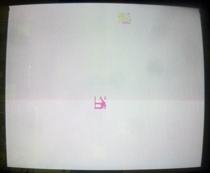
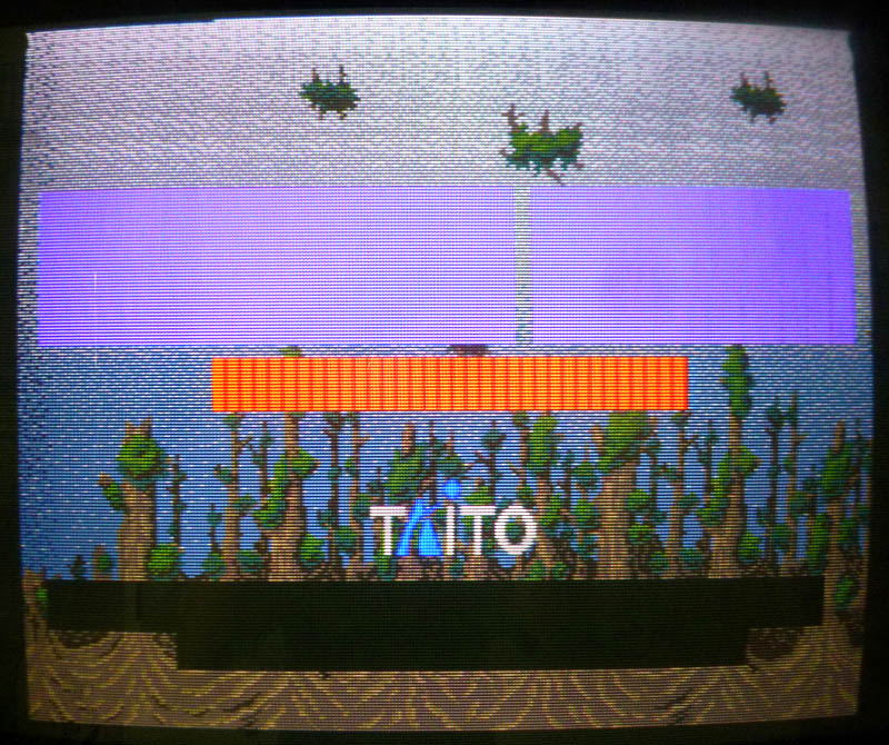
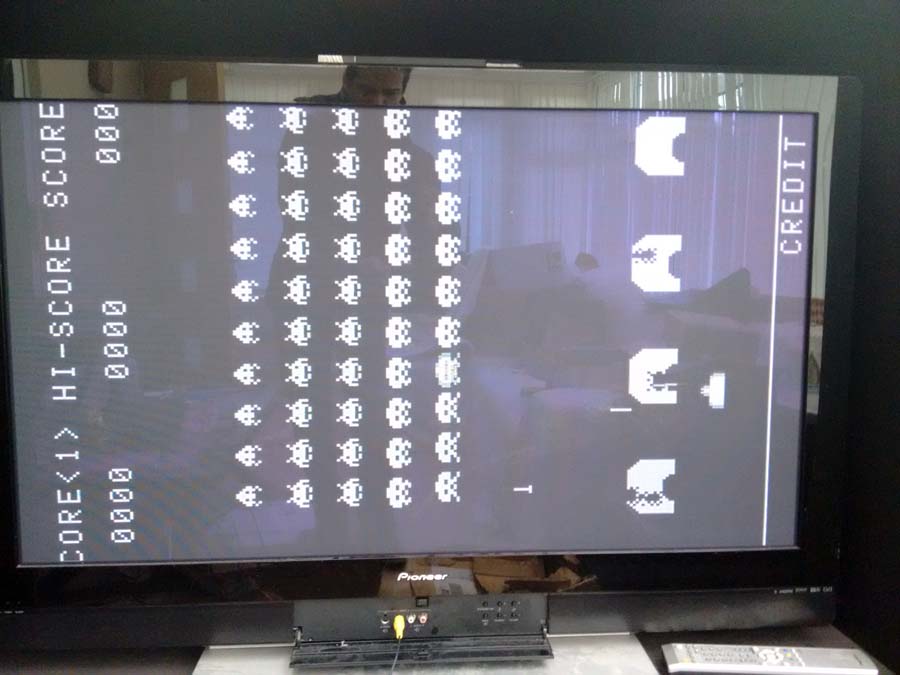
1) I got first stuck at this screen on boot:

Dumping the program ROMs at 17A and 18A and comparing them with the ones from MAME revealed the checksum for the one labeled 633J2 at 17A was bad so I burned the rom from MAME on a 27C512 EPROM and put it in place but no changes.
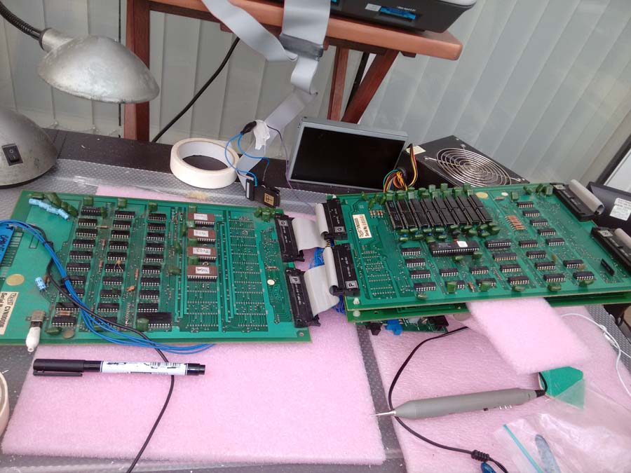
While checking the PCB with a scope, I traced a suspiciously weak signal from a couple of TTLs (which seemed ok) to a Fujitsu MB8464A RAM. Pins #7, 8 and 9 on this RAM were not pulsing (signal was stuck at 1,7 V).
These pins are address lines. They are connected to:
– Pins 7, 8, 9 on 18A and 17A (program ROMS)
– Pins 9, 10, 11 on 22A (63C09 CPU)
– Pins 114, 115, 57 on 10E (custom chip)
– Pins 114, 115, 57 on 18E (custom chip)
– Pins 1, 2, 3 on 14D (LS138 – Address decoder for I/O ports)
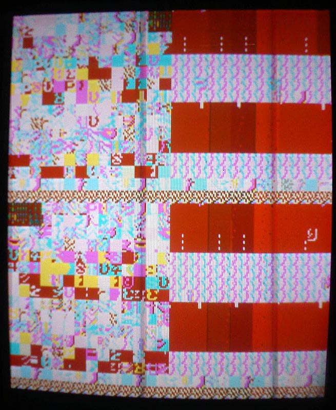
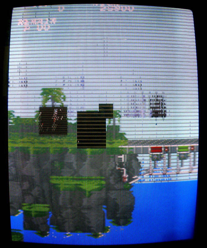
Replacing the LS138 at 14D didn’t change anything, not really surprising as it was related to I/O (but I didn’t really know that back in the time when I did it) so next I decided to replace the 63C09 CPU at 22A… And the game booted ! …with big graphical issues and no sound:

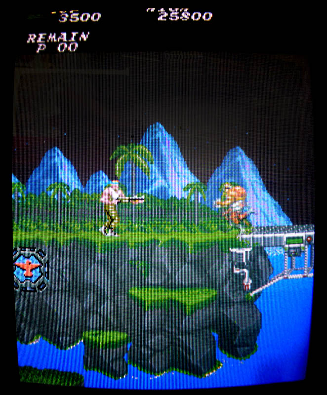
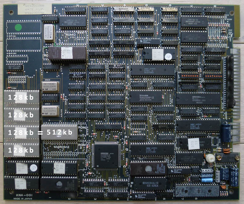
2) Graphics roms are the 4x 40 pins mask roms located at 7D, 7F, 16D and 16F. I’ve read online some people having problems with these chips and needed to replace them. The content of these roms is 256kb but I only had 512kb 27C400 EPROMs (equivalent pinout to mask roms) so I needed to double the size of each original 256kb roms to fit my 512kb EPROMs. A few tries revealed I had 3 bad roms (the ones at 7F, 16D and 16F) among the 4. All the graphics were now fine:

3) Good progress, but still no sound…
There are 2 chips in the sound part (located at 11A and 11B) that have their reference writings scrubbed, probably in factory to avoid bootleggers reproducing it. I’ve looked online to see if I could find pictures of other PCBs that could still have these labels visible, but all the ones I found had their writings scrubbed.
Anyway, it looked like these 2 chips were the sound generating chips. Looking in the MAME driver and on datasheets revealed it was a YM2151 coupled with a YM3012 D/A converter.
Looking at the pins of the YM2151 with a scope, I noticed there was no output signal on it (pin #21) while most of the other pins on the chip had pulsing signals. I desoldered it to put a new YM2151 in place and got a pulsing signal on the output pin… But still no sound.
I then started looking at the pins of the 63B09 sound CPU at 15A and found 2 dead signals at pins #16 and 18. These are address lines so I suspected the CPU and changed it. The sound was finally back. Everything is working fine now !
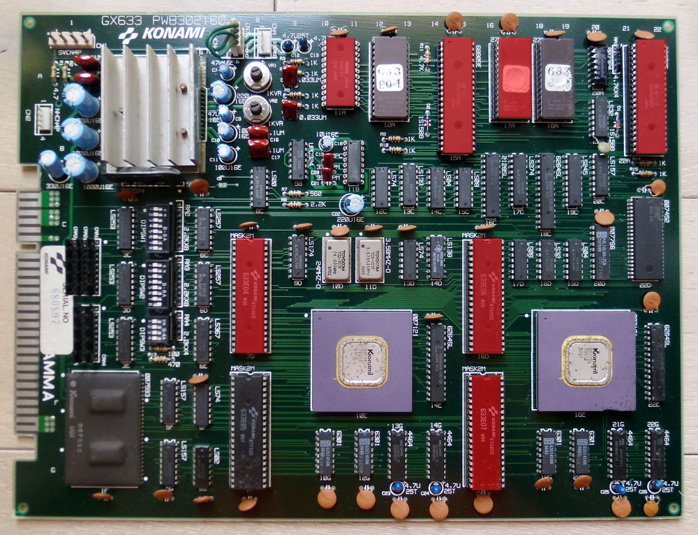
Here is a picture of my PCB with all the bad chips I replaced in red:

