Gryzor repair log #2

 PCB Repair Logs, Repair Logs  Comments Off on Gryzor repair log #2
Jan 232016
 

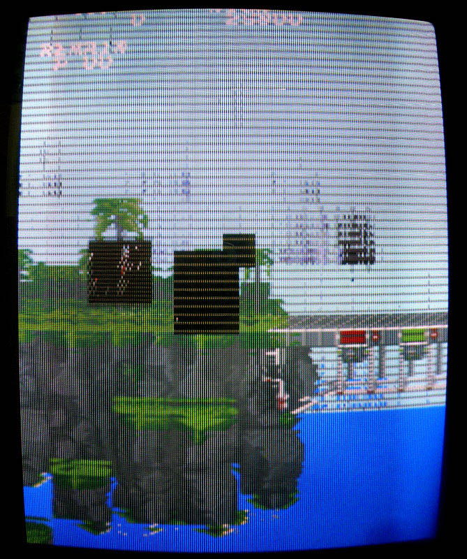
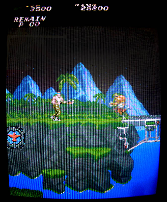
A friend got a Gryzor PCB working but with problems on some of the sprites (mostly enemies and items with half of the horizontal lines missing).

The 4 GFX MASK ROMs were tested ok on another Gryzor PCB. Looking with the scope on the RAMs revealed nothing really suspicious.

I then piggybacked the RAMs around the GFX part and quickly found the faulty one.
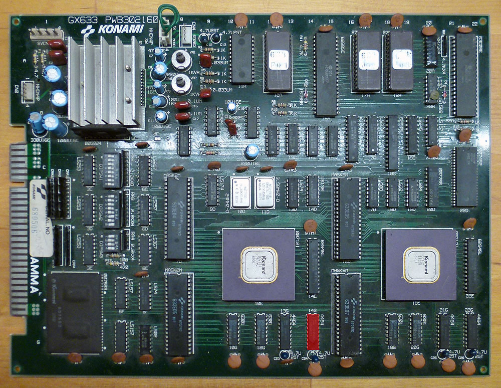
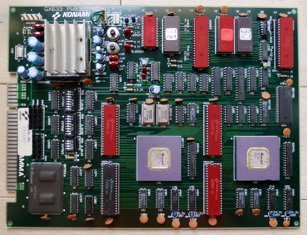
It was the NEC 8644FU12 at location 14G. This RAM is a 4464 (64k-word x 4-bit, same type than the ones I replaced on my recently repaired Final Star Force).
Here is a picture of the PCB with the faulty chip highlighted in red:

gryzor2-1

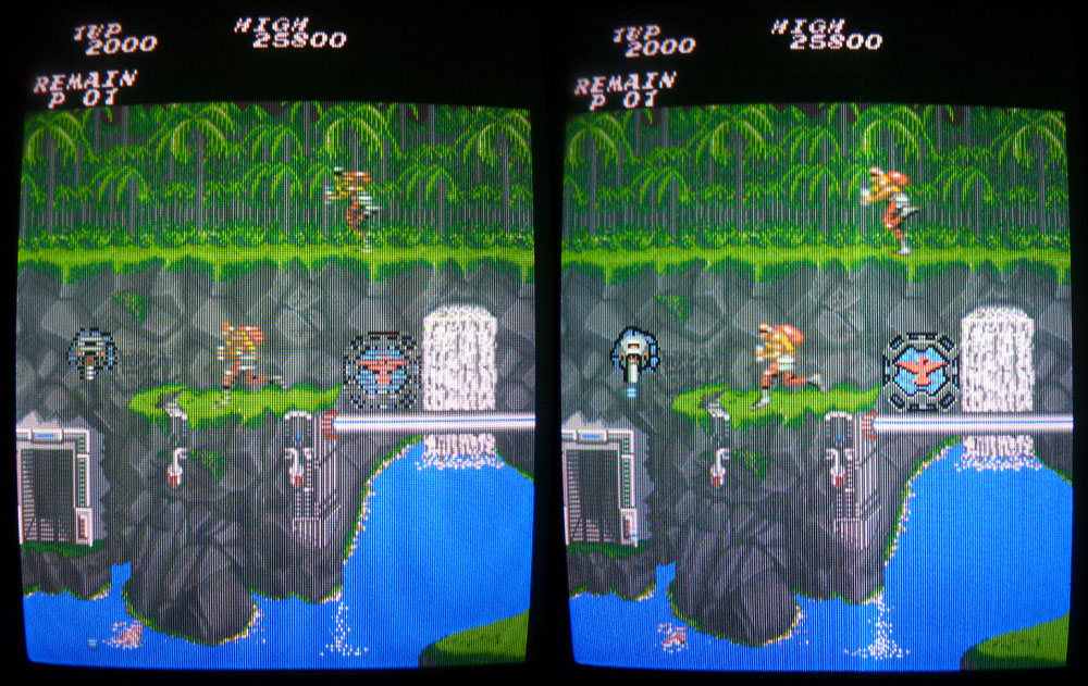
Piggybacking it with a compatible TMS 4464-12 restored all the sprites.
In fact, the problem was so small that it was impossible to see any suspicious signal on any of the pins of that RAM with the scope (every signal looked healthy). I replaced the chip and obviously got the PCB running perfectly.

Here is a before and after picture:

gryzor2-2

Jan 032016
 

Contra / Gryzor shares almost the same hardware specs with Combat School / Boot Camp, Fast Lane, Flak Attack / MX5000, Haunted Castle / Akumajô Dracula and Trick Trap / Labyrinth Runner.

But among these titles, it is the only game that offers a stereo output thru a 4-pin connector on the board (labeled CN2).

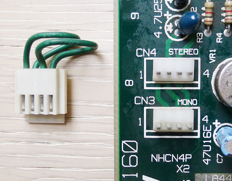
First, you have to select stereo by plugging a connector on CN4 (and put switch 4 of DIPSW3 to off).

contra-sound

The thing is that all the boards I’ve seen still delivers mono sound when you plug this connector (originally brought by Konami and present on the board) on the stereo plug. Why ? Because it doesn’t have the good wiring…

As shown on the picture above, this connector originally comes with pin #1 wired to #2 and pin #3 wired to #4. In that way and plugged on the stereo connector (CN4), it mixes channel 1 and channel 2 from the YM3012 DAC to the LA4445 amp which results a mono output.

To separate the channels, you have to simply modify the connector by wiring pin #1 to #3 and pin #2 to #4.
Now plug it on CN4 and enjoy stereo sound out of CN2. 🙂

There are other Konami games that use the same connector to choose mono or stereo. I’m not sure about the wiring for every game. To my knowledge they are:

Salamander
– Jackal / Top Gunner
Devil World / Dark Adventure
– Gradius II / Vulcan Venture

– Ajax

Lightning Fighters / Trigon (stereo works without modification of the connector)
– Parodius
(stereo works without modification of the connector)
Surprise Attack (that game seems to have a mono sound design, despite the stereo connector present on the board)

ps. If anybody knows if the original wiring on these boards allows to deliver stereo sound or any other board that is using this connector, I would be glad to know and add it here.

Gryzor repair log #1

 PCB Repair Logs, Repair Logs  Comments Off on Gryzor repair log #1
Dec 142015
 

First I would like to thank hezkezl and channelmanic on the KLOV forum for their help when I started diagnosing this Gryzor PCB last Year.

I finally got it repaired…

1) I got first stuck at this screen on boot:

gryzor0

Dumping the program ROMs at 17A and 18A and comparing them with the ones from MAME revealed the checksum for the one labeled 633J2 at 17A was bad so I burned the rom from MAME on a 27C512 EPROM and put it in place but no changes.

While checking the PCB with a scope, I traced a suspiciously weak signal from a couple of TTLs (which seemed ok) to a Fujitsu MB8464A RAM. Pins #7, 8 and 9 on this RAM were not pulsing (signal was stuck at 1,7 V).

These pins are address lines. They are connected to:
– Pins 7, 8, 9 on 18A and 17A (program ROMS)
– Pins 9, 10, 11 on 22A (63C09 CPU)
– Pins 114, 115, 57 on 10E (custom chip)
– Pins 114, 115, 57 on 18E (custom chip)
– Pins 1, 2, 3 on 14D (LS138 – Address decoder for I/O ports)

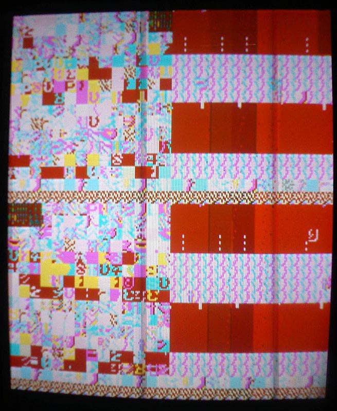
Replacing the LS138 at 14D didn’t change anything, not really surprising as it was related to I/O (but I didn’t really know that back in the time when I did it) so next I decided to replace the 63C09 CPU at 22A… And the game booted ! …with big graphical issues and no sound:

gryzor2

2) Graphics roms are the 4x 40 pins mask roms located at 7D, 7F, 16D and 16F. I’ve read online some people having problems with these chips and needed to replace them. The content of these roms is 256kb but I only had 512kb 27C400 EPROMs (equivalent pinout to mask roms) so I needed to double the size of each original 256kb roms to fit my 512kb EPROMs. A few tries revealed I had 3 bad roms (the ones at 7F, 16D and 16F) among the 4. All the graphics were now fine:

gryzor3

3) Good progress, but still no sound…

There are 2 chips in the sound part (located at 11A and 11B) that have their reference writings scrubbed, probably in factory to avoid bootleggers reproducing it. I’ve looked online to see if I could find pictures of other PCBs that could still have these labels visible, but all the ones I found had their writings scrubbed.

Anyway, it looked like these 2 chips were the sound generating chips. Looking in the MAME driver and on datasheets revealed it was a YM2151 coupled with a YM3012 D/A converter.

Looking at the pins of the YM2151 with a scope, I noticed there was no output signal on it (pin #21) while most of the other pins on the chip had pulsing signals. I desoldered it to put a new YM2151 in place and got a pulsing signal on the output pin… But still no sound.

I then started looking at the pins of the 63B09 sound CPU at 15A and found 2 dead signals at pins #16 and 18. These are address lines so I suspected the CPU and changed it. The sound was finally back. Everything is working fine now !

Here is a picture of my PCB with all the bad chips I replaced in red:

gryzor4b