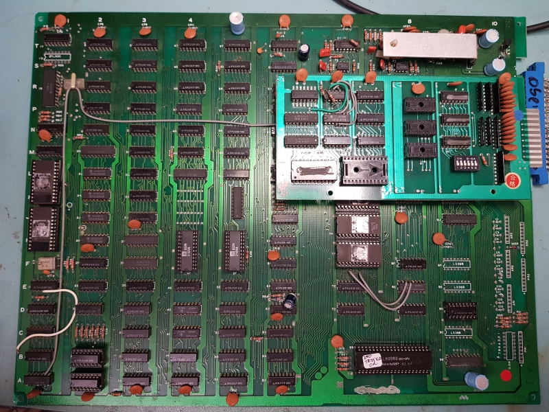
Hammy sent me a couple of boxes of PCB’s recently. Among them was this Scramble bootleg PCB.

I’m still not sure if this pinout is unique but I had to figure this one out for myself.
Finding the VCC and GND pins is easy enough and just a matter of checking continuity from a know IC.
Once I had the power pins hooked up I fired it up and used the scope to probe for video signals. As long as the board boots the RGB should be easy to identify and as long as sync is being generated we should be able to find a 15khz signal somewhere.
Fortunately for me that is exactly what I found so I hooked them up and got this
I already knew this game didn’t match anything in MAME but I pulled all the ROM’s anyway and dumped them.
The Z80 is socketed on this PCB so I plugged the Fluke 9010 in and carried out the ROM tests. All the ROM’s could be read without a problem.
Next on to the RAM.
I originally looked at the wrong MAME source for this board. I looked at galaxian.cpp but I should have been referring to galaxold.cpp. Because of this error I ended up wasting a bit of time looking for a fault that didnt exist.
One this PCB the work RAM is between addresses $4000 – $47ff.
On the riser PCB I could see 2 x 2114 RAM’s which are a 4 bit memory but this would only give me 1024 (0x3ff)bytes on RAM and I was expecting double that. Removing the riser board revealed the second set of 2114 chips.
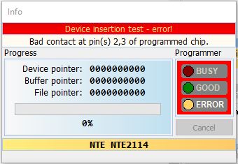
Running the RAM check on the Fluke gave me RAM errors in the upper half of the range which I determined was on the riser PCB. I removed both of them to be sure and found one was giving errors on 2 address pins

Replacing this gave me this
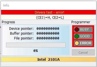
Error 3 doesn’t exactly give me much to work with so I just went round the other RAM ranges. There is some screen RAM at address range $5000 – $50ff. This failed.
This RAM in 2 x 2101 and as luck would have it it is already socketed.
I removed both and tested them and both failed


I have plenty of these spare due to my dealings with early Nintendo boards so swapped them right out.
We have success and with the audio hooked up we get this.
The riser board on this thing seems to be for the control inputs
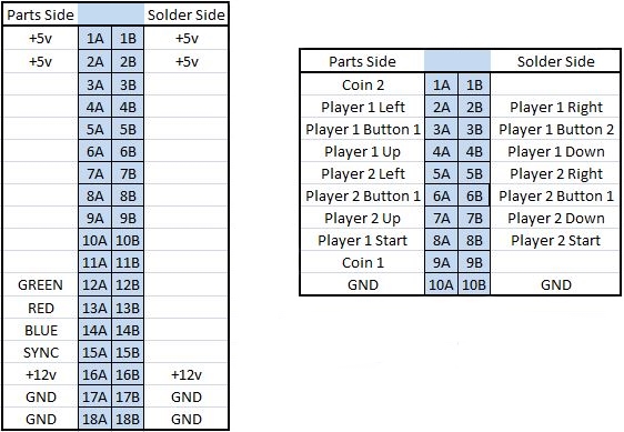
Here is the pinouts I got for the PCB. There is likely a few things missing like coin counter but I’m not bothered about that.


Sorry, the comment form is closed at this time.