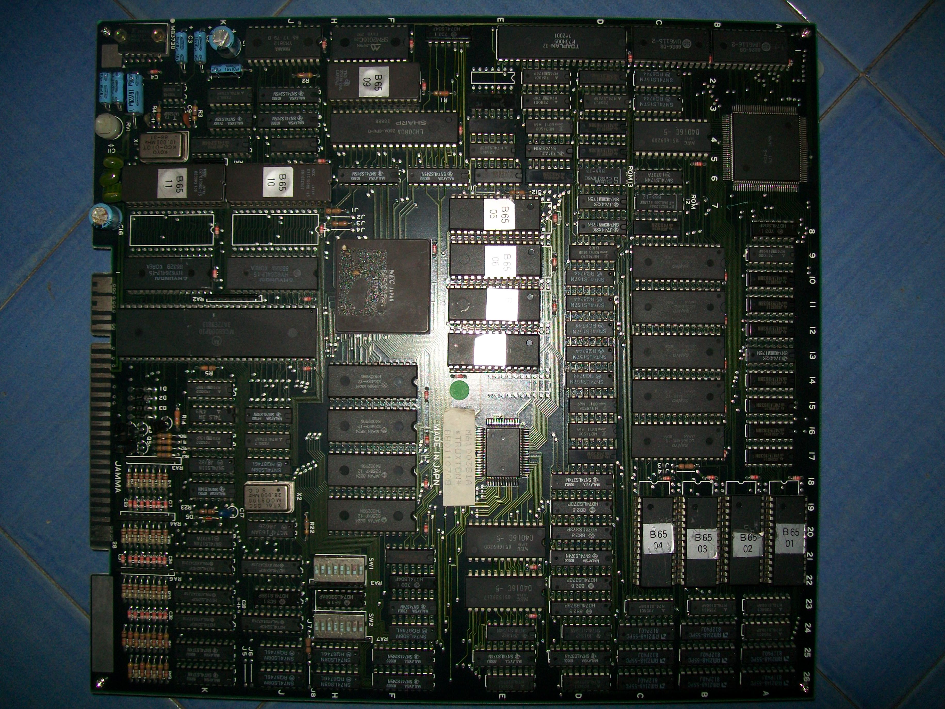
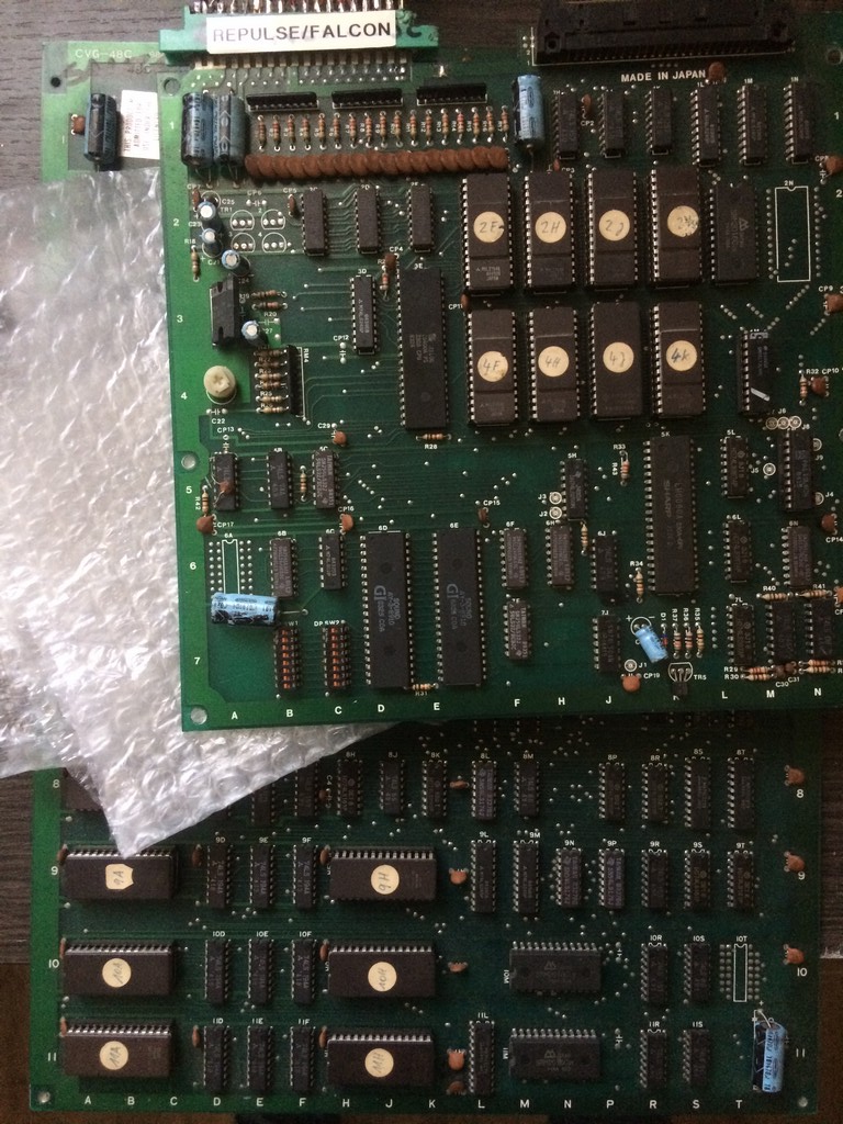
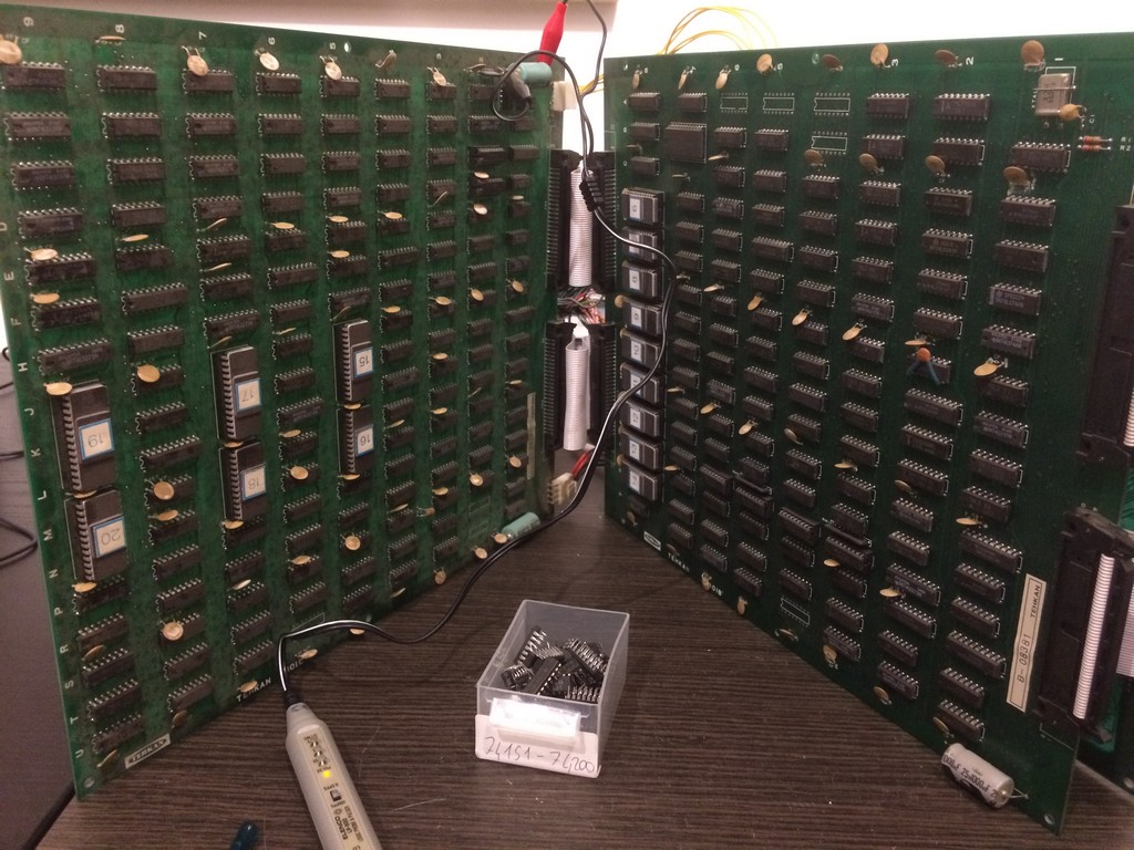
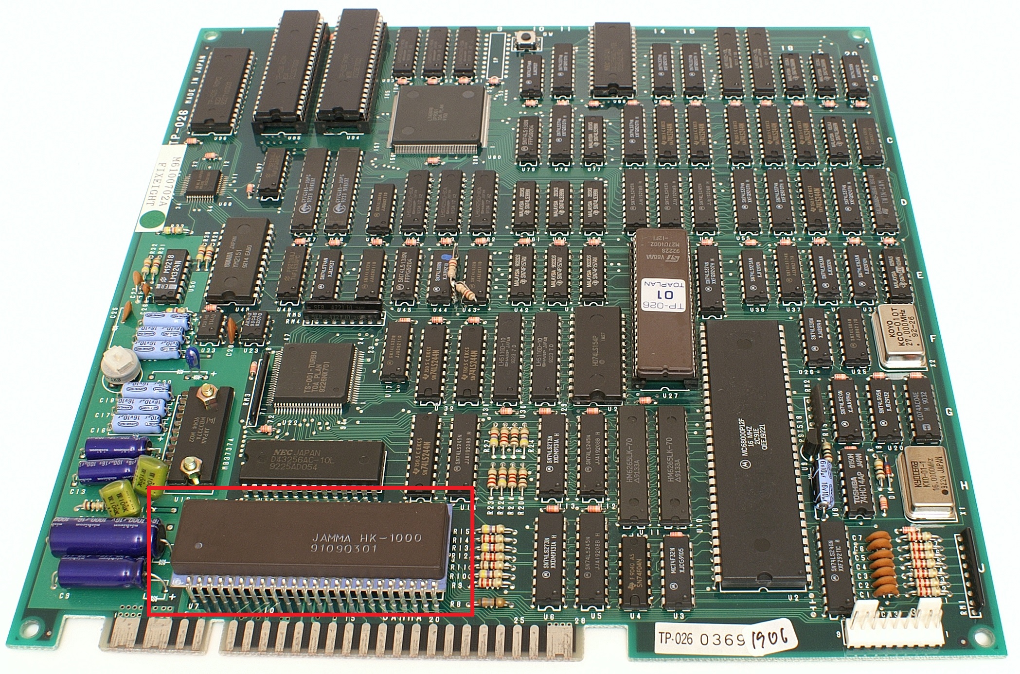
Some months ago I received for a repair this Tatsujin Oh PCB (known outside Japan as Truxton II)
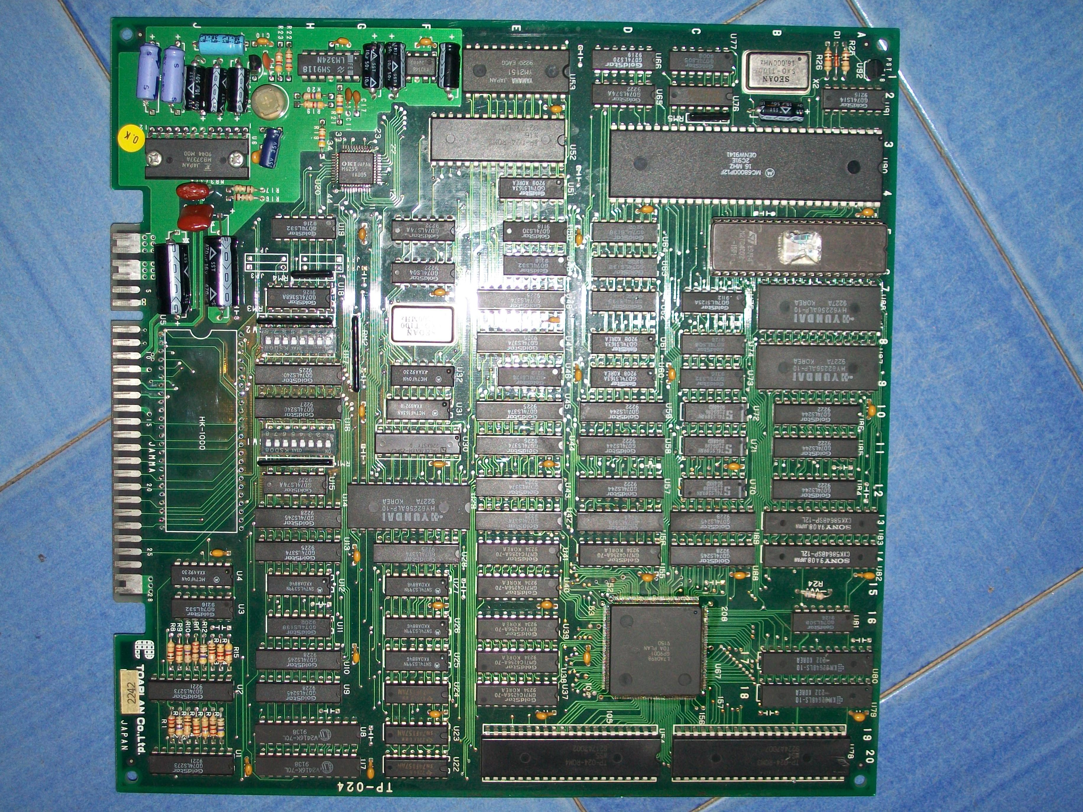
As you can see from the above picture, the custom ‘HK-1000’ (used for inputs) in front of JAMMA edge was missing but this was not the main problem, board won’t sync up:
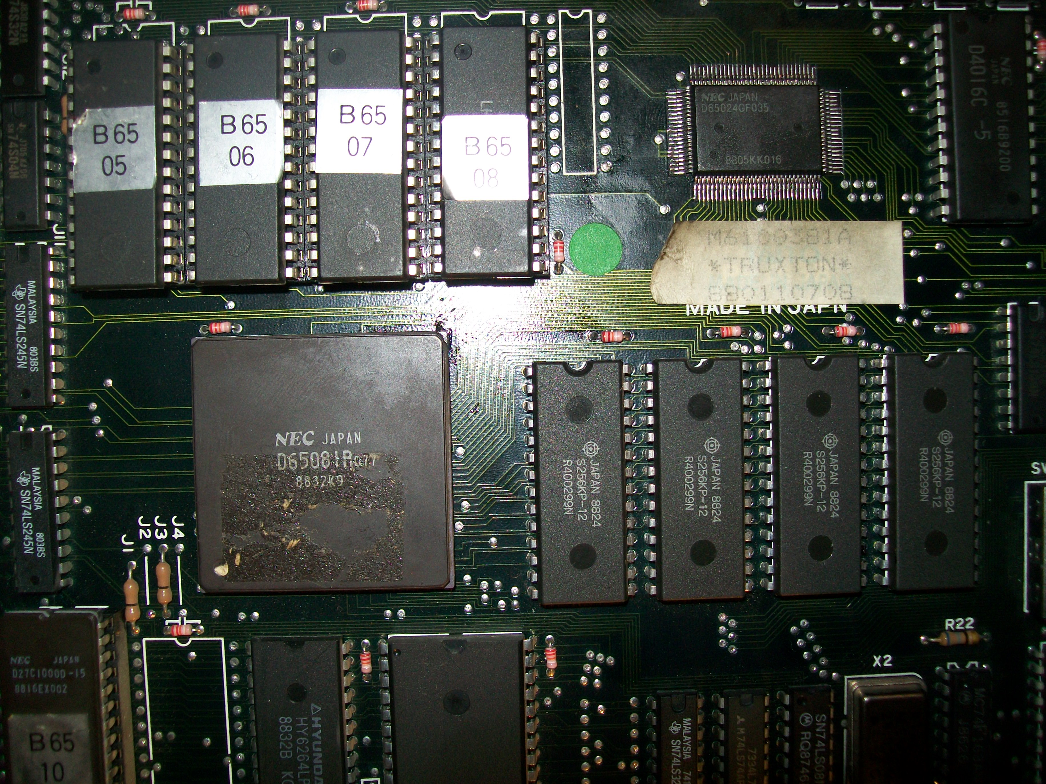
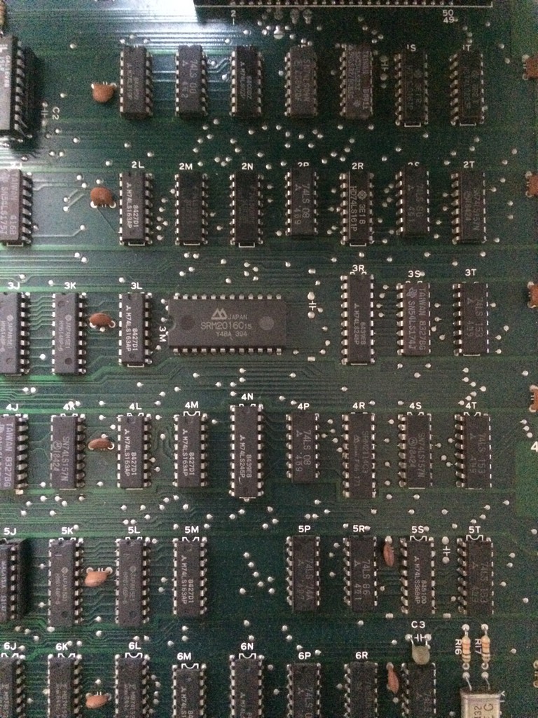
All the graphics and video timing signal (HSYNC, VSYNC, etc..) are generated by a large surface mounted ASIC (208 pins QFP package) marked ‘GP9001’:
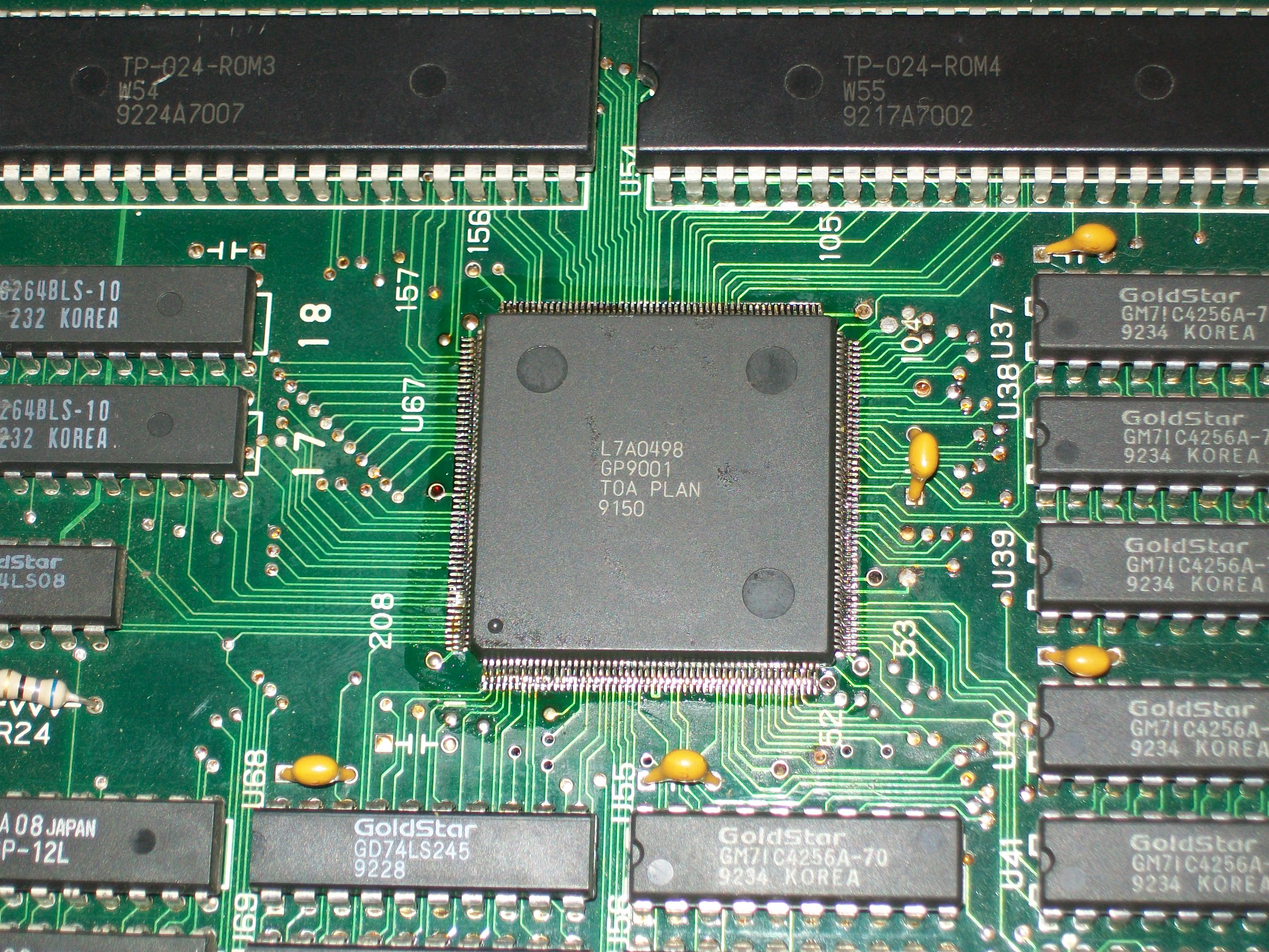
You can find its pinout on page 32 of the Knuckle Bash schematics:
https://www.jammarcade.net/files/Schematics/Arcade/Knuckle%20Bash.pdf
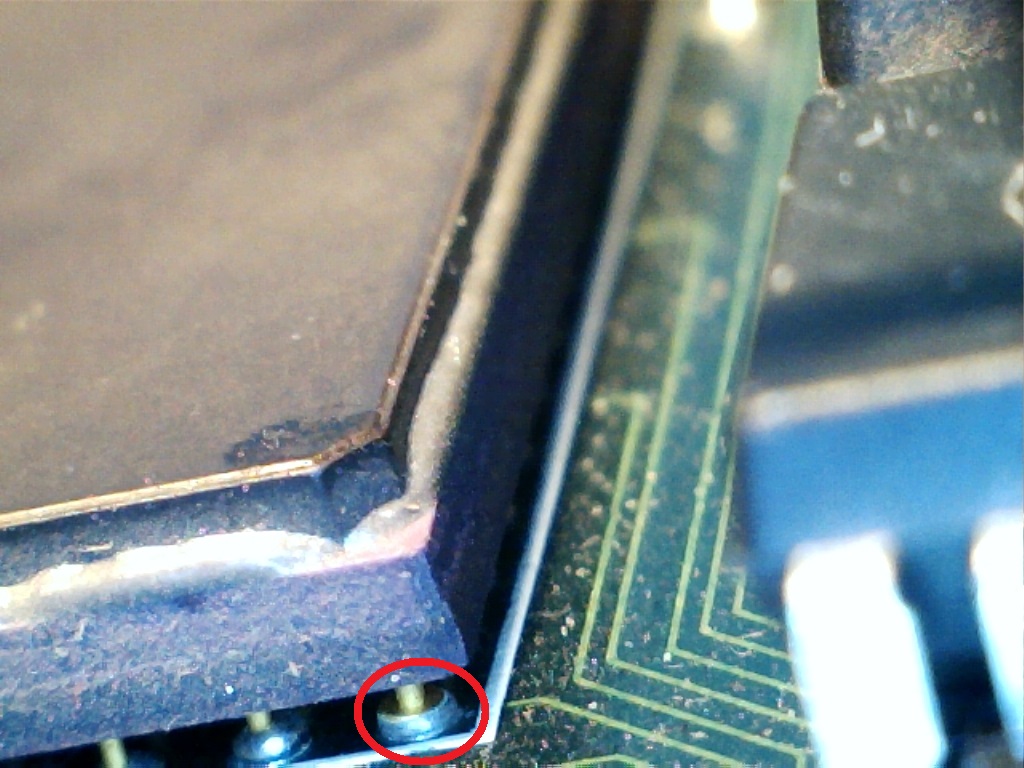
The IC was previously reworked by someone in a bad way, many pins were bridged together, flux residuals were not cleaned.So I decided to remove it :
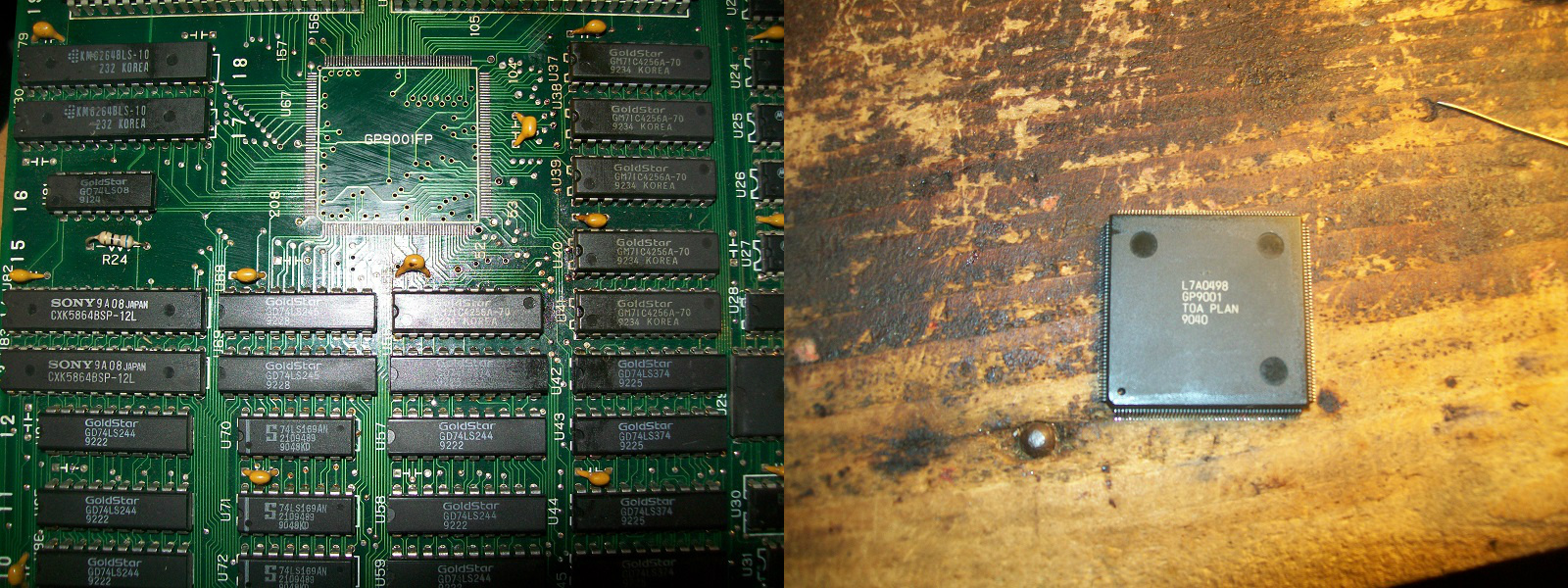
and solder it again:
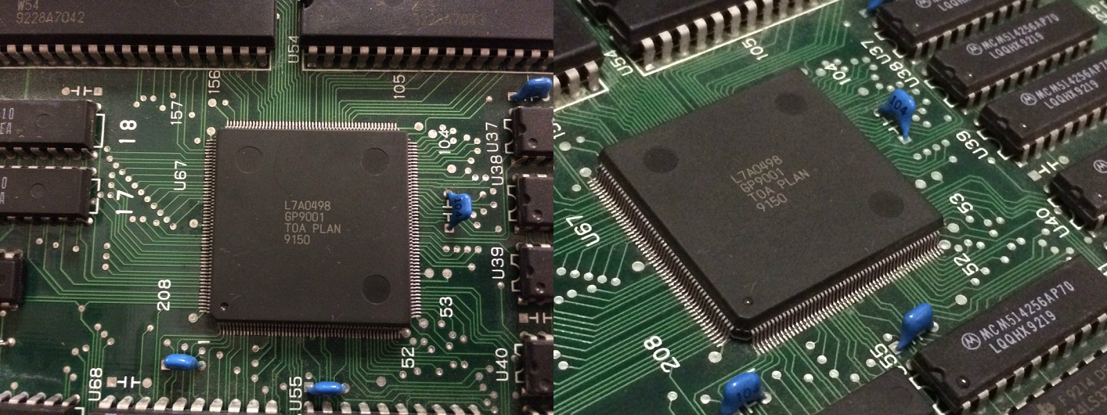
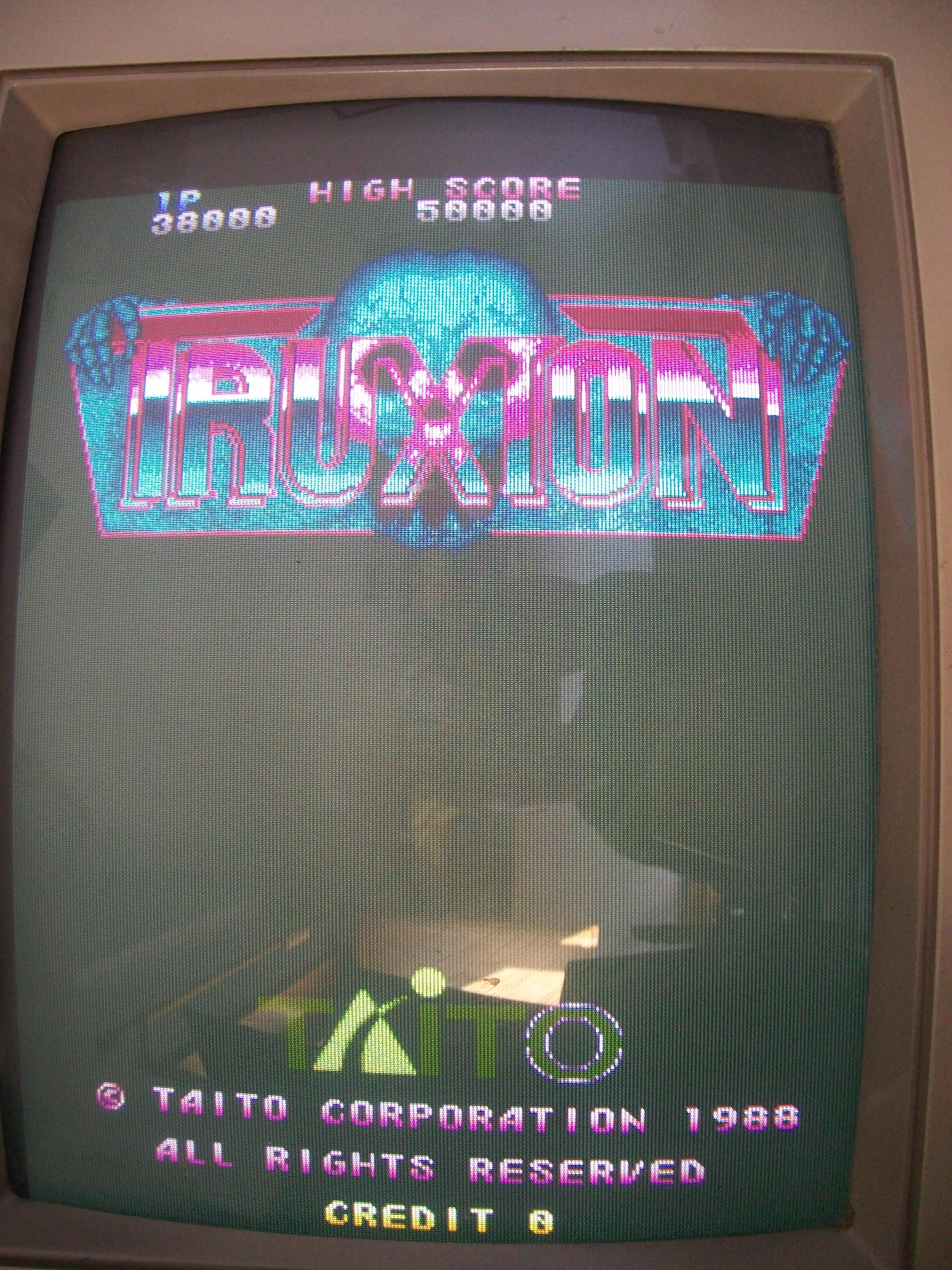
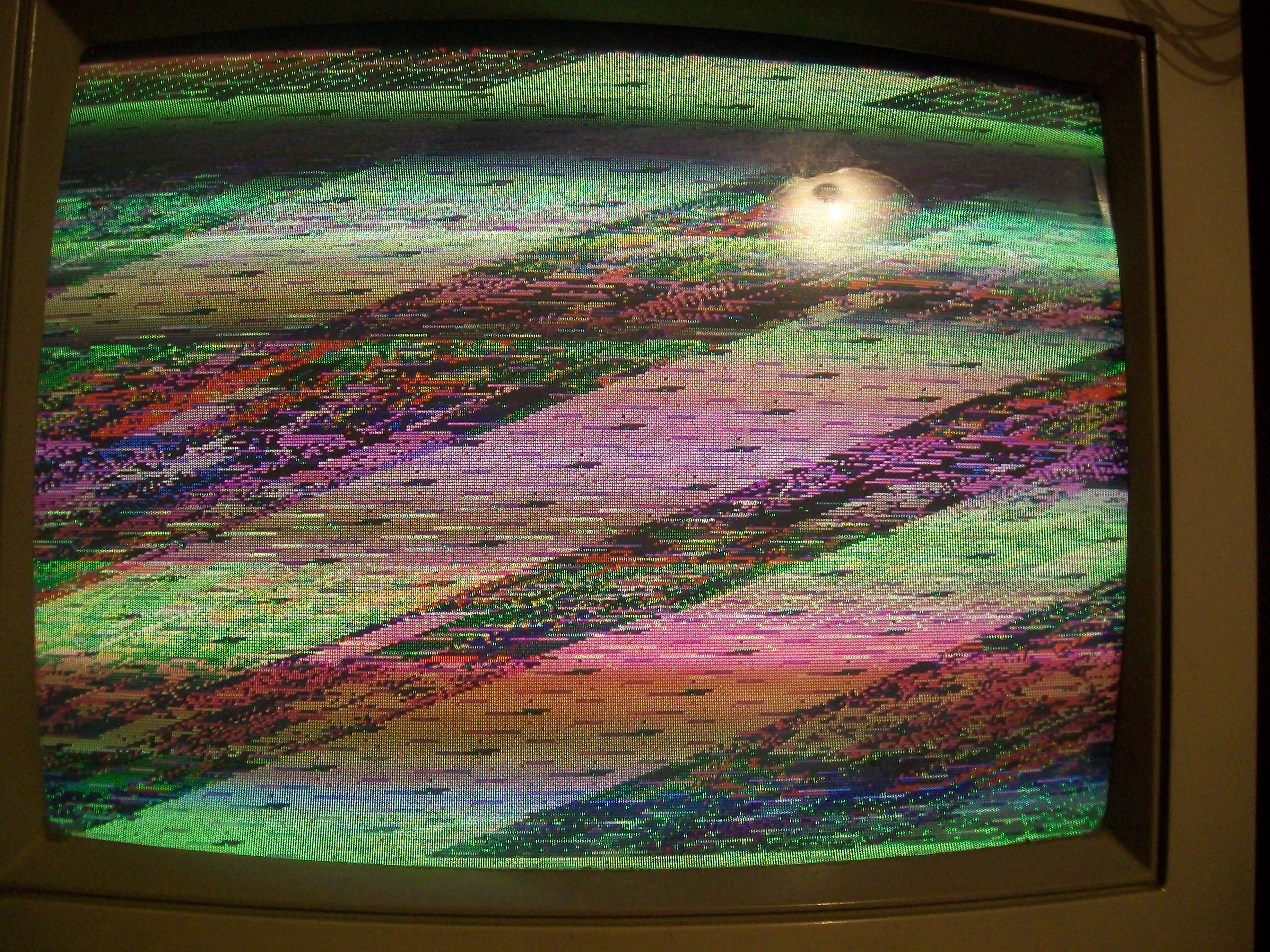
Happy with the result I powered up the board again and I was greeted but this static garbage screen:
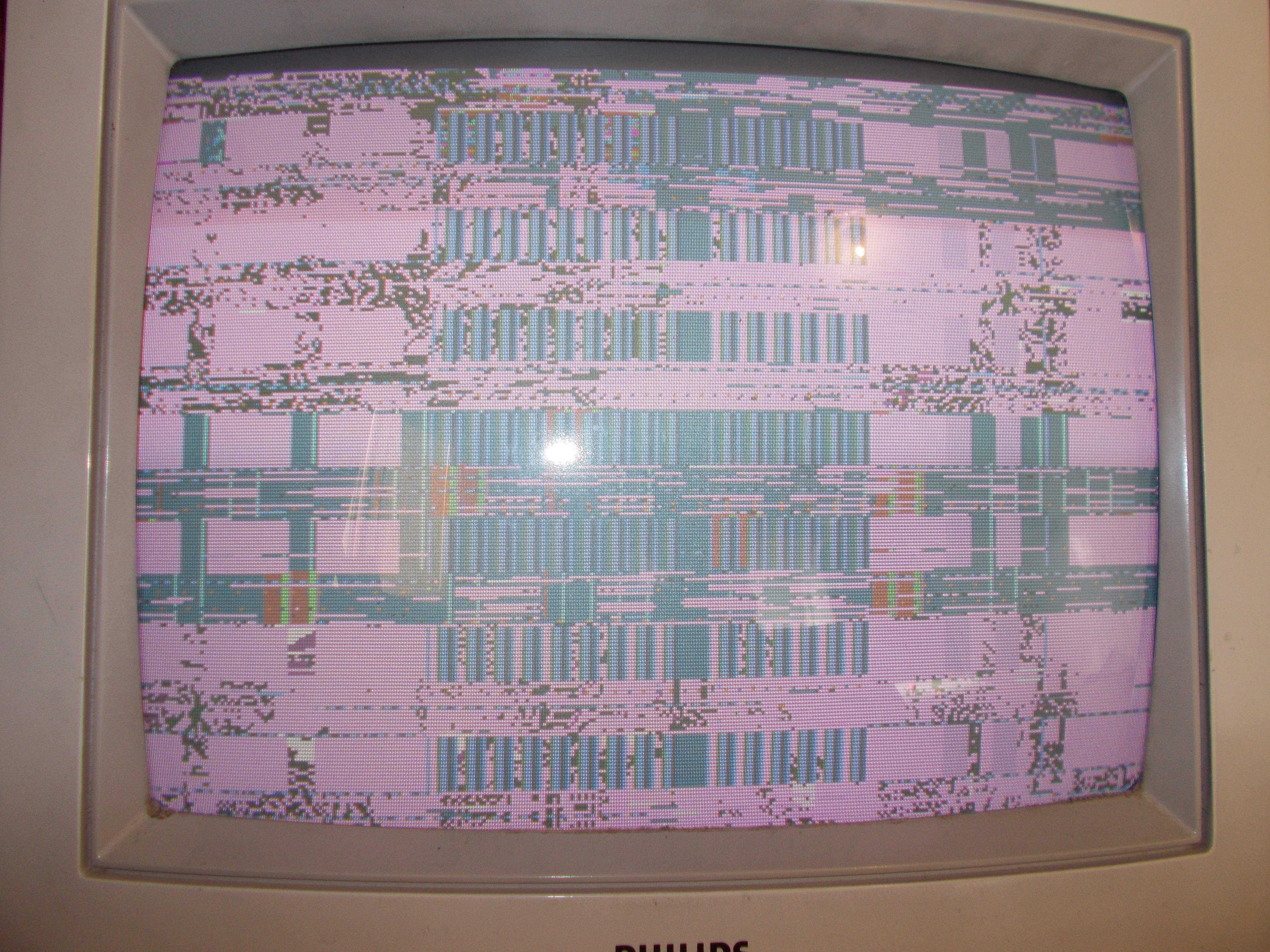
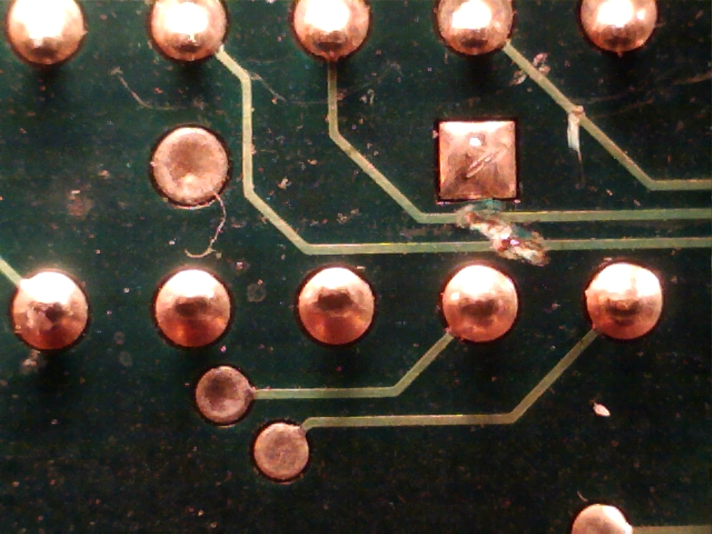
Probing the main 68000 CPU revealed no activity on data bus.Doing a visual inspection of PCB I found a couple of severed traces on solderside just around the CPU area:
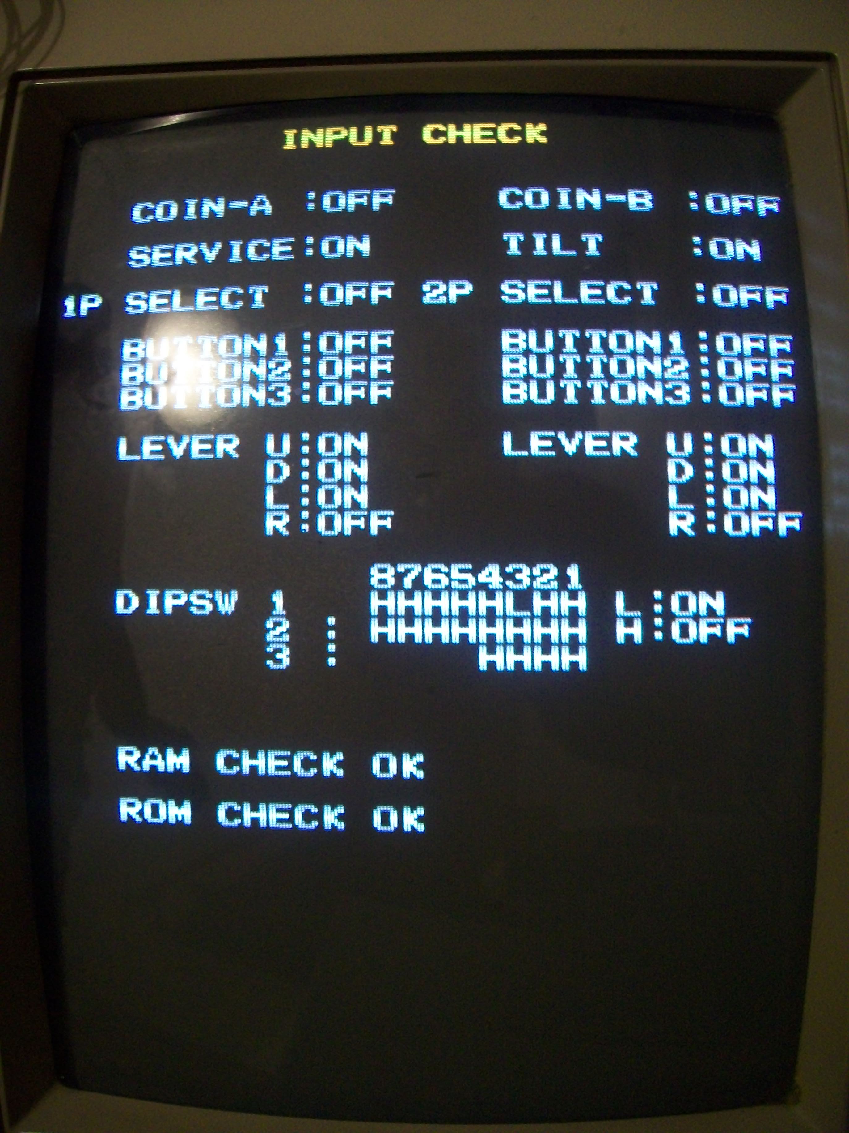
Patching them allowed the board to boot but, obviously, due the lack of the ‘HK-1000’, the game was stuck on a ‘TILT’ error message:

Input check in TEST mode reported ON most of them :
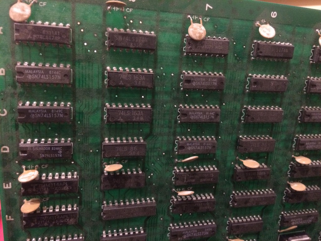
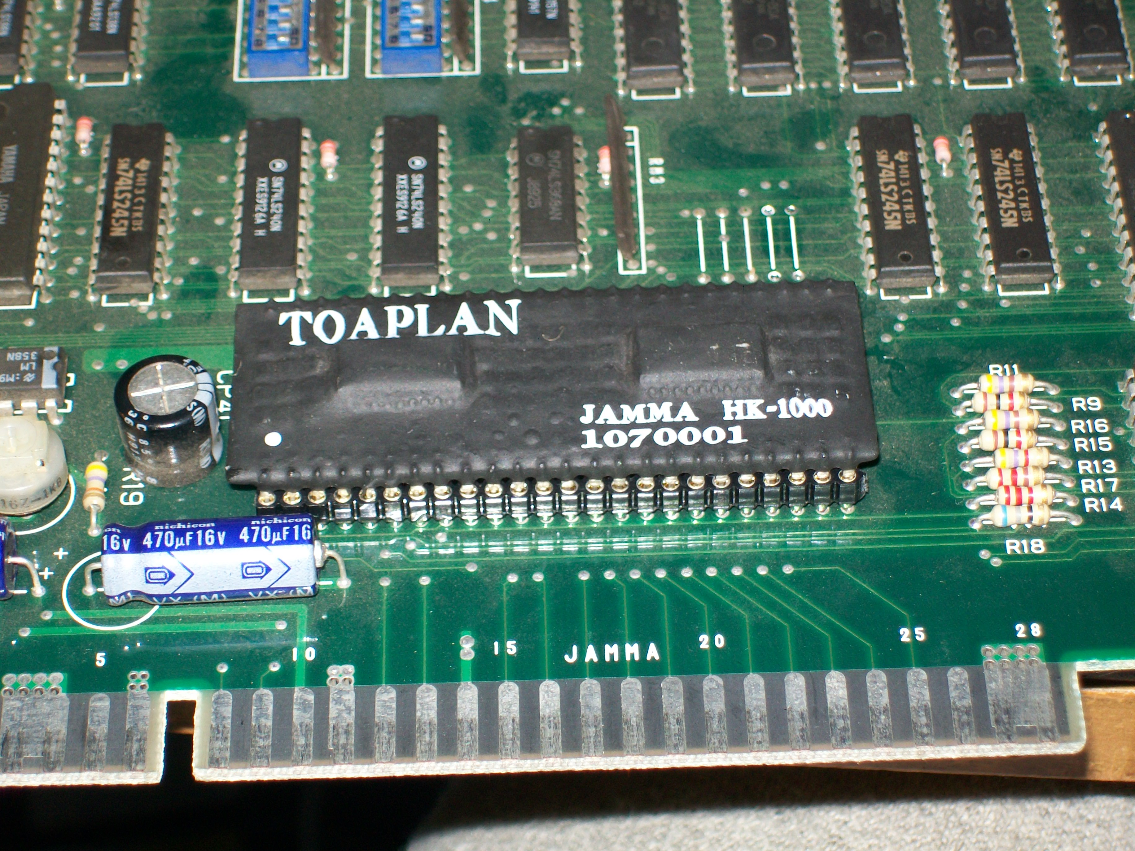
Now some words on the ‘HK-1000’.As said, this custom handles all inputs and it’s has been adopted in later Toaplan PCBs.There are two revisions of it, the early one has a ceramic package and due this nature it’s very prone to damage and failure.This revision is used on Truxton II/Tatsujin Oh and FixEight:
The newer revision is more robust and it’s used on Ghox, Pipi & Bibis:
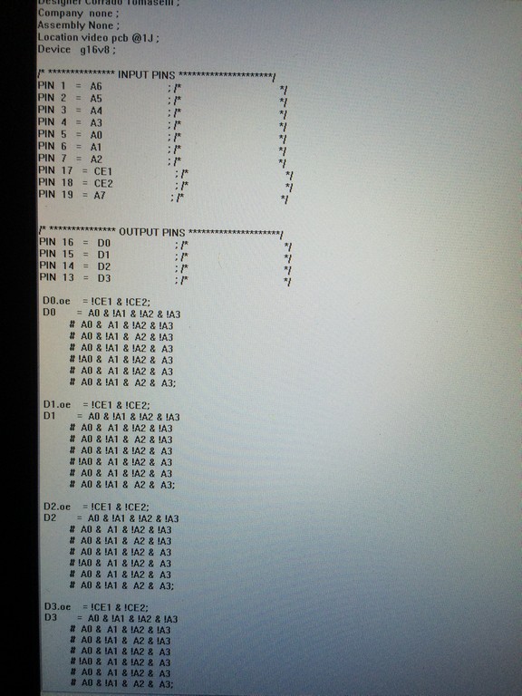
Back to repair, from available info it seems the functions of this custom can be reproduced using a couple of 74LS240 (actually the custom handles also the coin counters and lockout but we can omit it), this is not a suprise for me since a lot of previous Toaplan boards use same design with these TTLs (see for example Truxton, Wardner, Hellfire and other).Doing some tests with a single 74LS240 I was able to successfully map some inputs turning off the TILT error
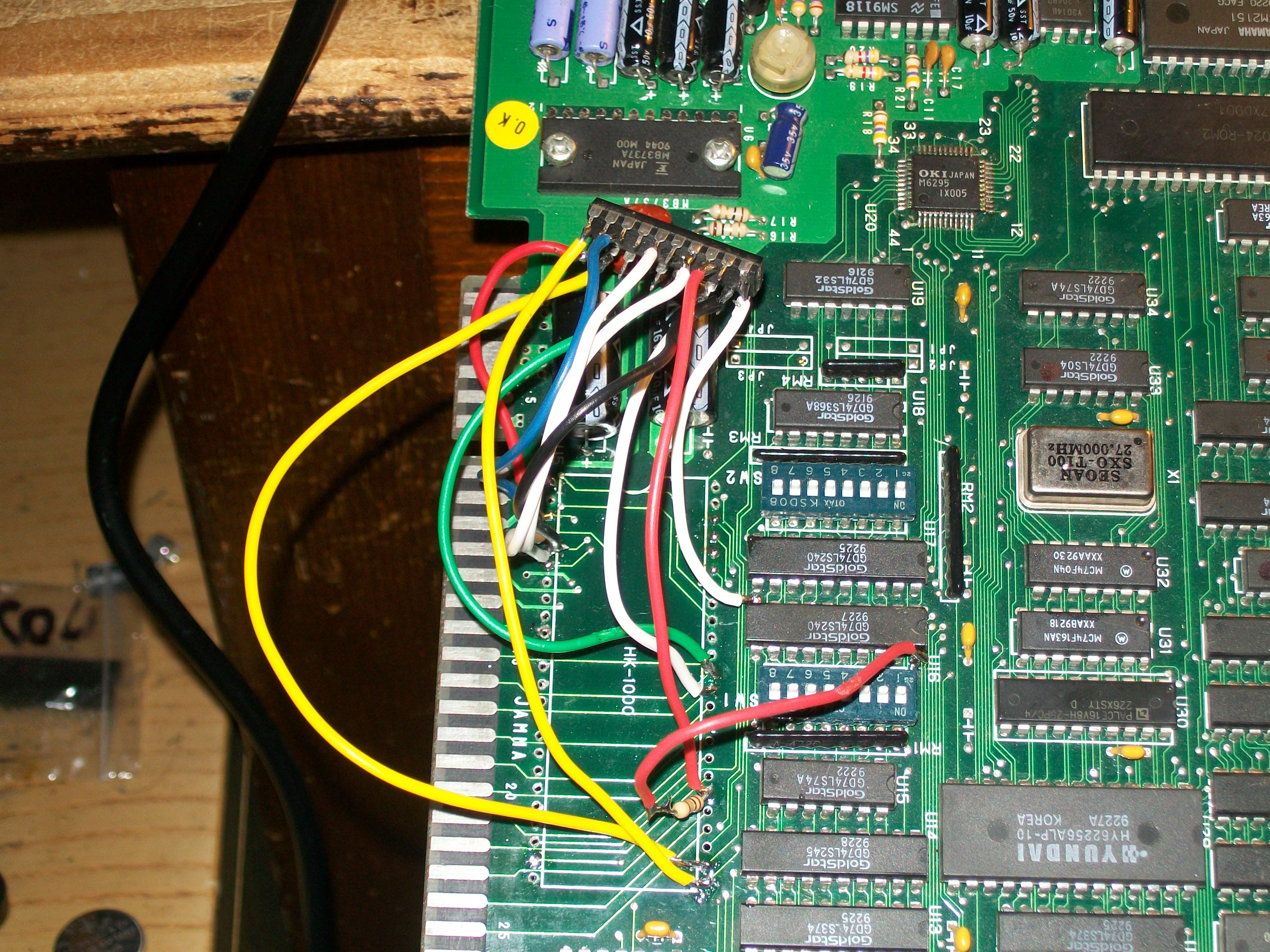
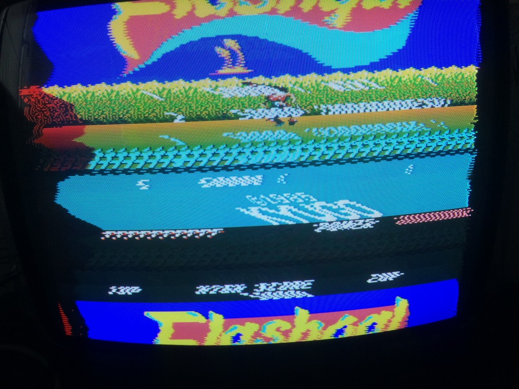
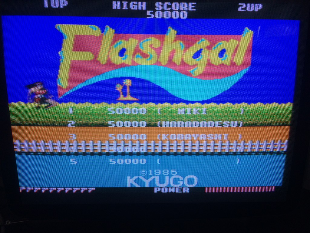
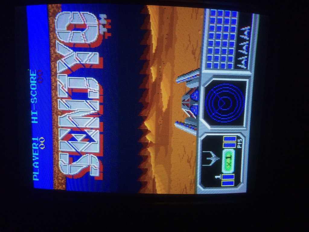
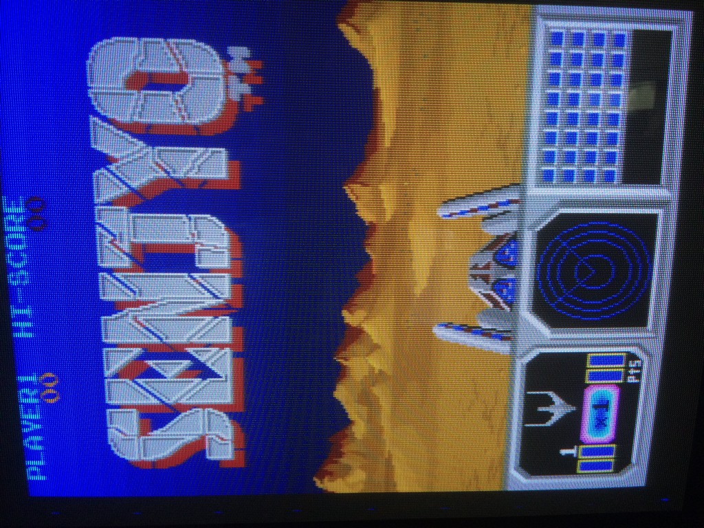
This allowed me to enter in game :
Later, owner of the board installed the missing HK-1000 and confirmed the board was perfectly working after my repair:
P.S.
I’m currently drawing schematics for the replacement of the HK-1000 and I will post here my results.Stay tuned.