JEDutil is a program included with MAME.
While MAME doesn’t directly use PAL dumps for emulation it does look to load them if they are available. As each programmer has its own output format when reading these chips (some are really different, other not so much) there arose the need to have a standard.
Read here for more information
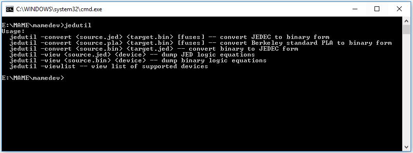
What can JEDutil do?

It can convert a programmer usable .jed file to a MAME usable .bin file
It can convert from the MAME usable .bin file back to a programmer usable .jed file
It can be used to view the equations of any support .jed or.bin file
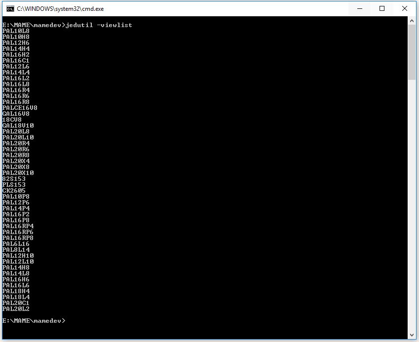
To see a list of supported devices you use the “-viewlist” argument

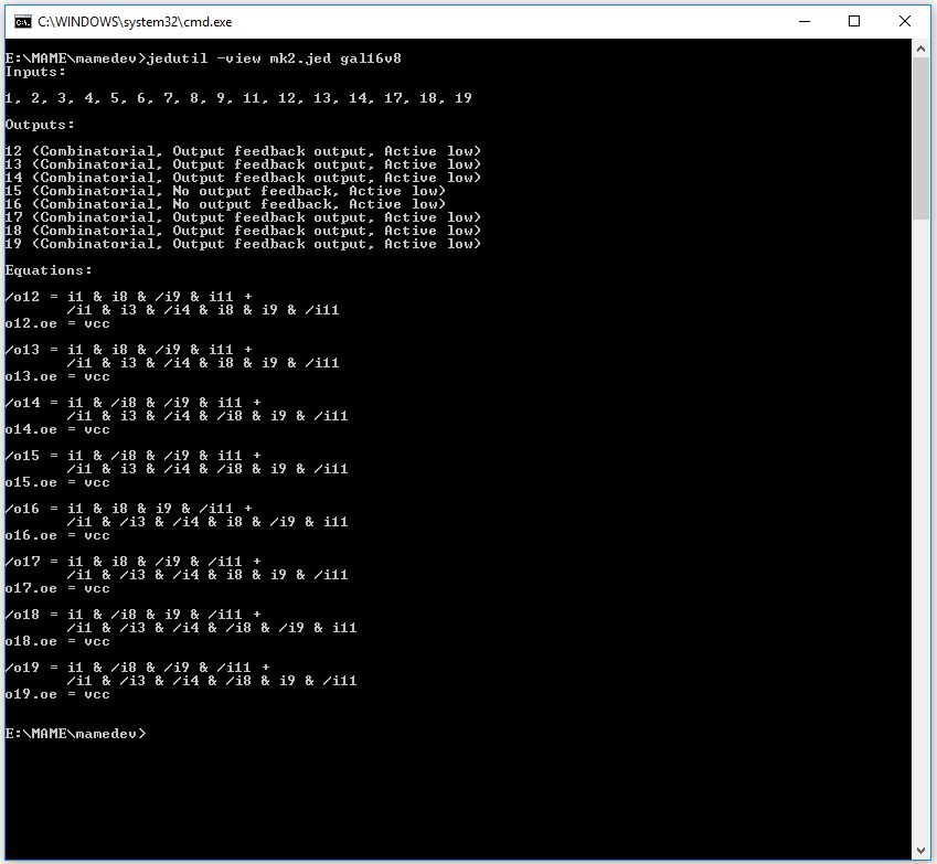
To view equations use the “-view” argument

These equations show exactly how the outputs works in relation to any given input and I believe is self explanatory to those who are looking.
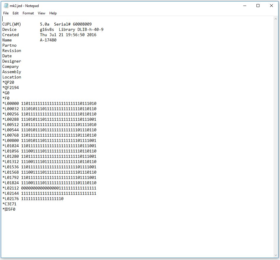
Here is what the file im using for this example looks like in a text editor

You can clearly see it was created using WinCUPL.
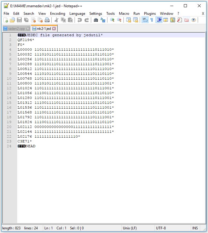
Here is what a JEDutil created .jed file will look like opened up in a text editor

It looks very similar to the WinCUPL created file and most programmers i’ve encountered can load these without issue. One exception to that (and there are certainly others too) is the Needham EMP-20 which seems to use its own binary format that is not compatible with the MAME format.
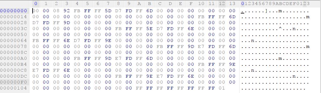
Here is what a MAME usable binary file for a .jed will look like in a hex editor

There are clear difference between the binary and jedec files and should be easy to spot if you are not 100% sure what you have got.
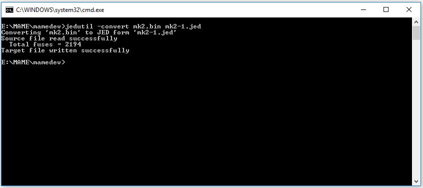
Converting a MAME binary to a Jedec file
If you want to use the PAL dumps found in MAME on real hardware then you MUST convert them from their binary format back into .jed format.
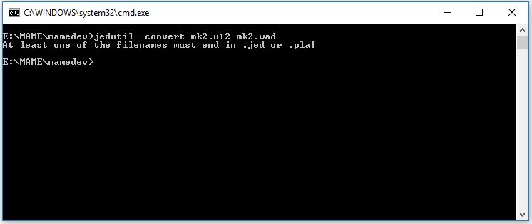
You need to use the “-convert” argument

Note the filename extensions used here. The output file must be .jed (or .pla) or the conversion will fail and you will see this useful message

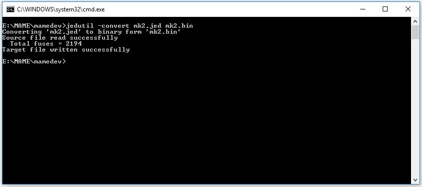
Converting a Jedec file to a MAME binary
To convert a .jed file into a MAME .bin file you simply use the same command but swap the filename extensions.

This will create the binary file. The original .jed file will remain untouched.
The only time I can really think of anyone needing to convert to a MAME binary is if you are submitting your dumps for inclusion to MAME
I’ve yet to ever find a use for the Berkeley PLA conversion so I haven’t covered it in here but if required it should be straight forward enough to work out.
Other Errors
Occasionally you might see some more cryptic error messages when using JEDutil. While there are things you can do to try and get around these they might also be a sign of a corrupt file or one of incorrect format.
The Jedec file format has two checksums both found at the end of the file.
The first is the fusemap checksum and the second is the transmission checksum
In the example used above the fusemap checksum is “3E71”. I believe the “C” part is always present.
The transmission checksum is “D5F0”
The fusemap checksum is the 16bit sum of all the 8bit fuse values.
The transmission checksum is a little more. Using the same example as before
The transmission checksum is a 16 bit sum of all the ASCII characters between (and including) the STX and ETX markers.
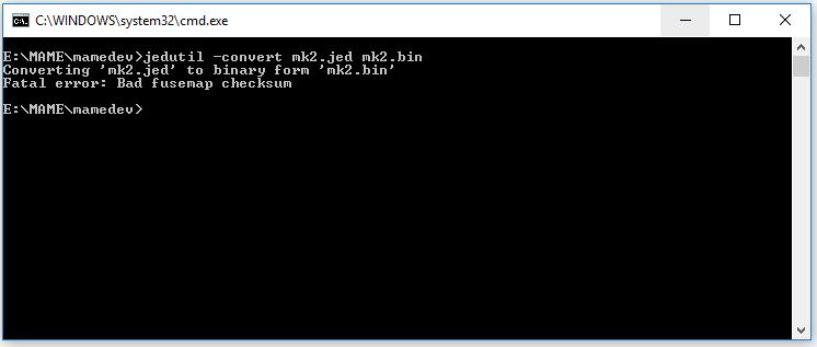
If the fusemap checksum if incorrect but the transmission checksum is correct then you will get this message

If the transmission checksum is incorrect then you will get this message

I believe you will get this message even if there is a fusemap checksum error as well.
You can disable the transmission checksum by changing it to “0000”.
In the past if I got stuck working with a strange .jed file I have loaded it into my programmers software and saved it back. This rewrites all the checksums to be correct. Your milage may vary!
There may be other errors, maybe not. I’ve not come across any other to really bother myself about.