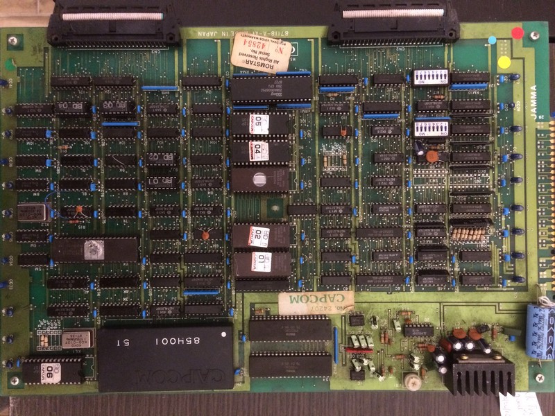
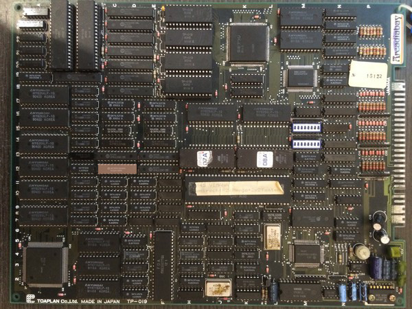
Got this pcb from a friend for a repair.
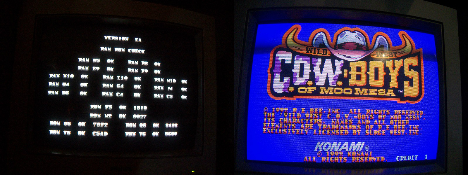
At first it showed a OBJECT RAM ERROR which was fixed by reflowing the custom BCU-2 which had some lifted pins.
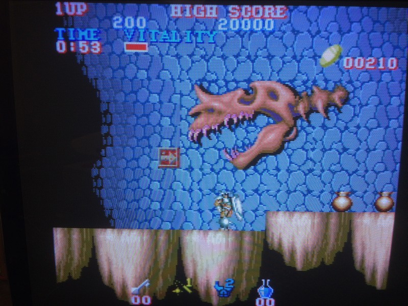
At this point the game showed all the sprites with black pixels
After some trials, I could locate the circuit which draws the sprites.
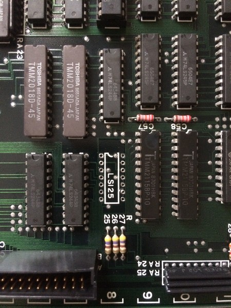
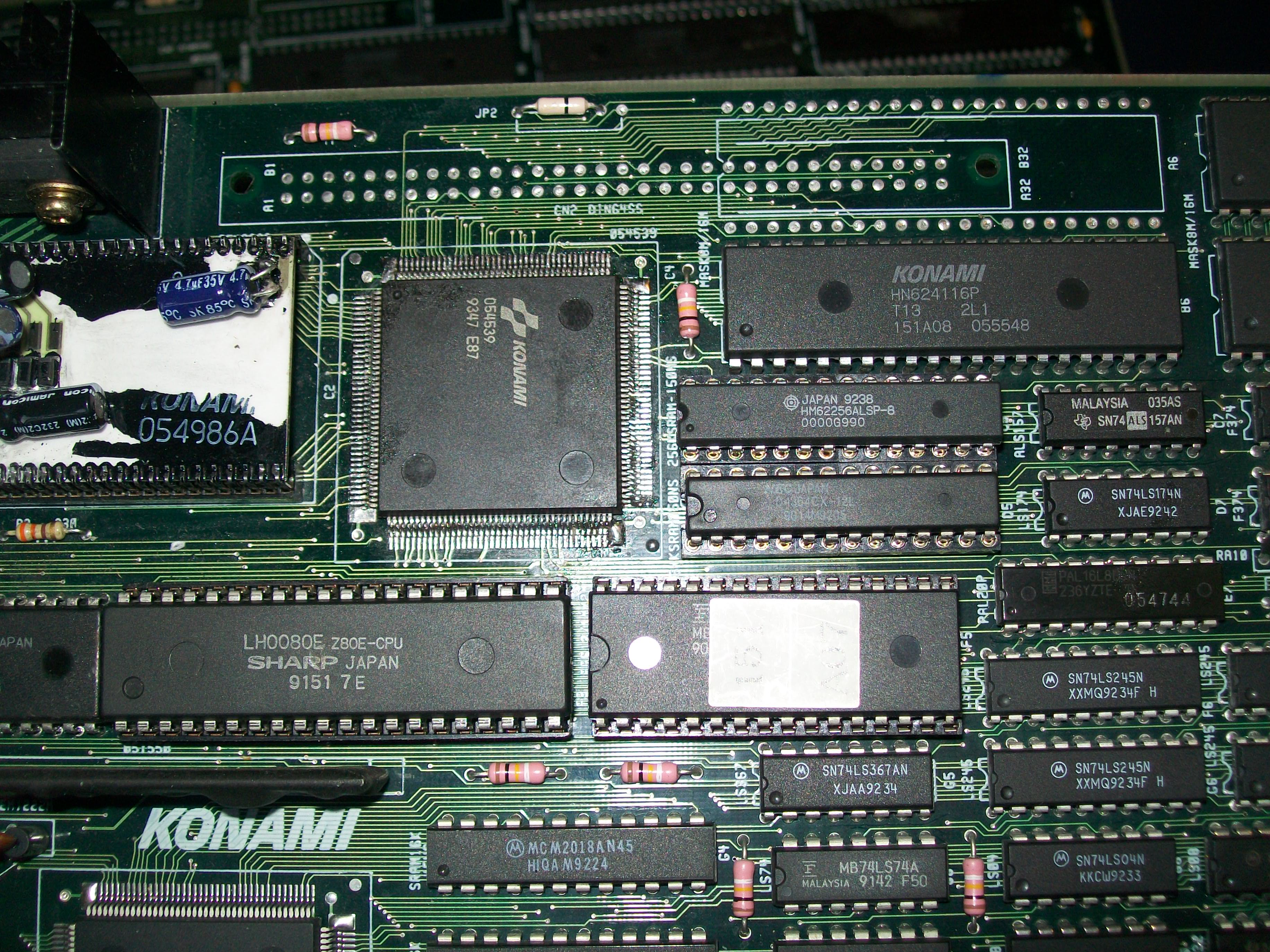
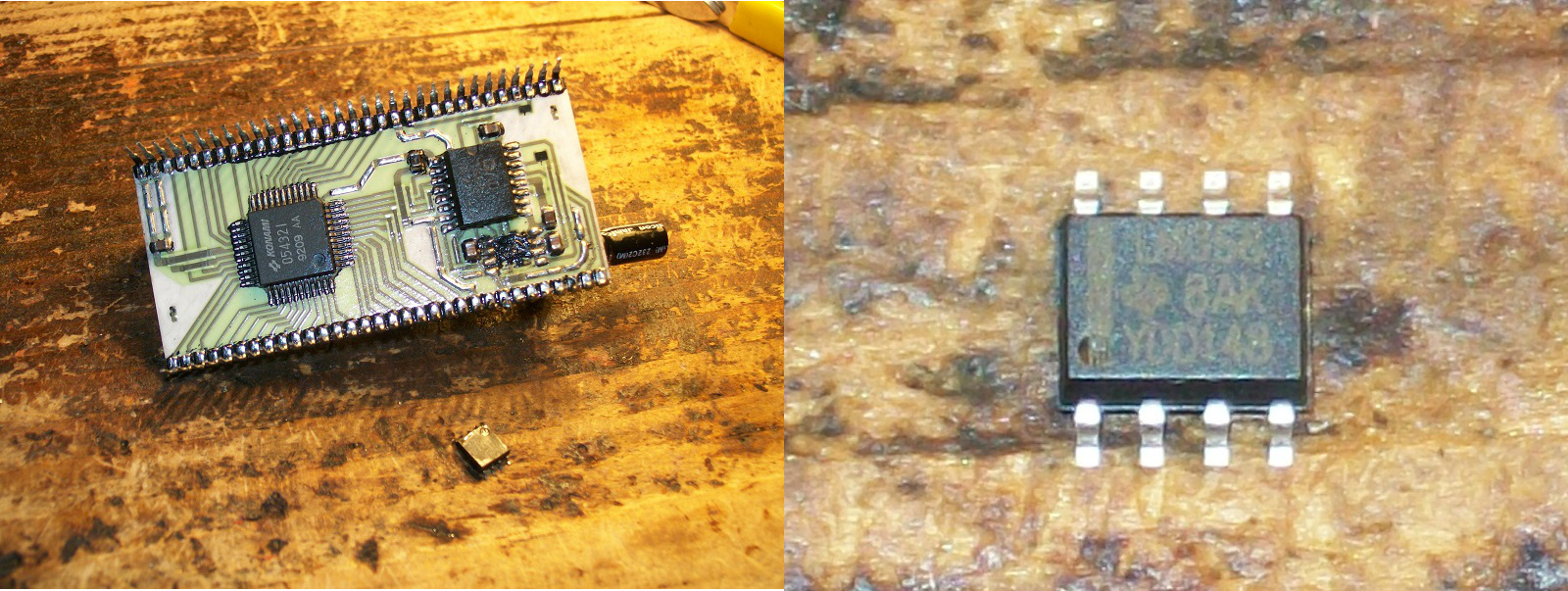
There are 4x srams 6116, by piggybacking sram @12C ( marked in white on the below pic) the sprites were shown perfectly.
After exchanging it, I got another issue

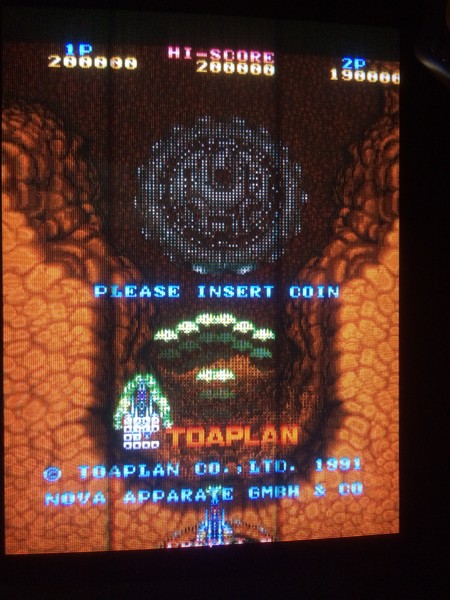
From the above picture it is difficult to see, but on the upper half of the screen, the alternate lines of the sprites were displaced on the bottom side.
I was really puzzled and I was sure that something else got broken in the meanwhile.
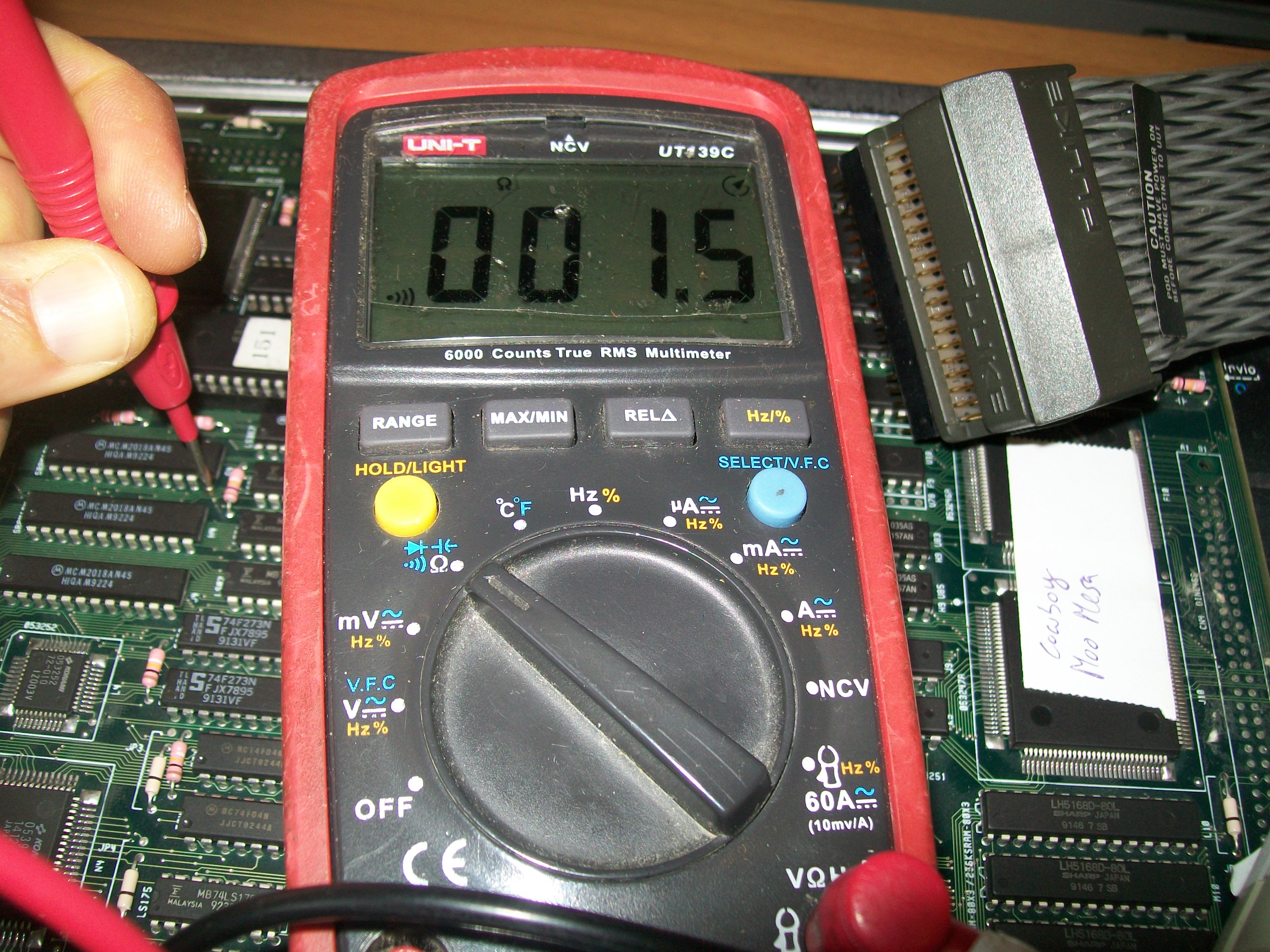
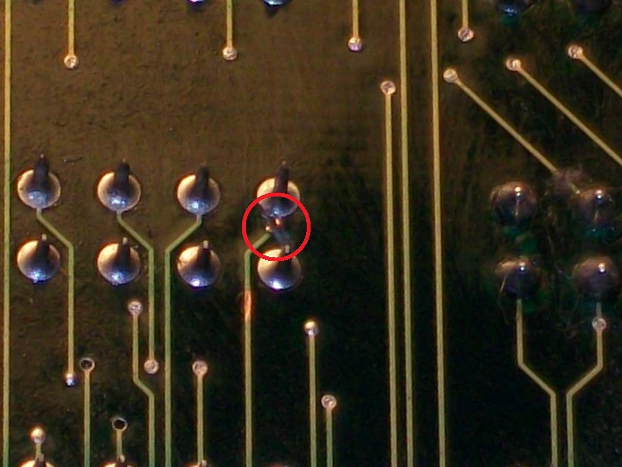
After some days of blindly checking other parts of the circuits, I decided to probe the address pins of the very same sram I exhanged.
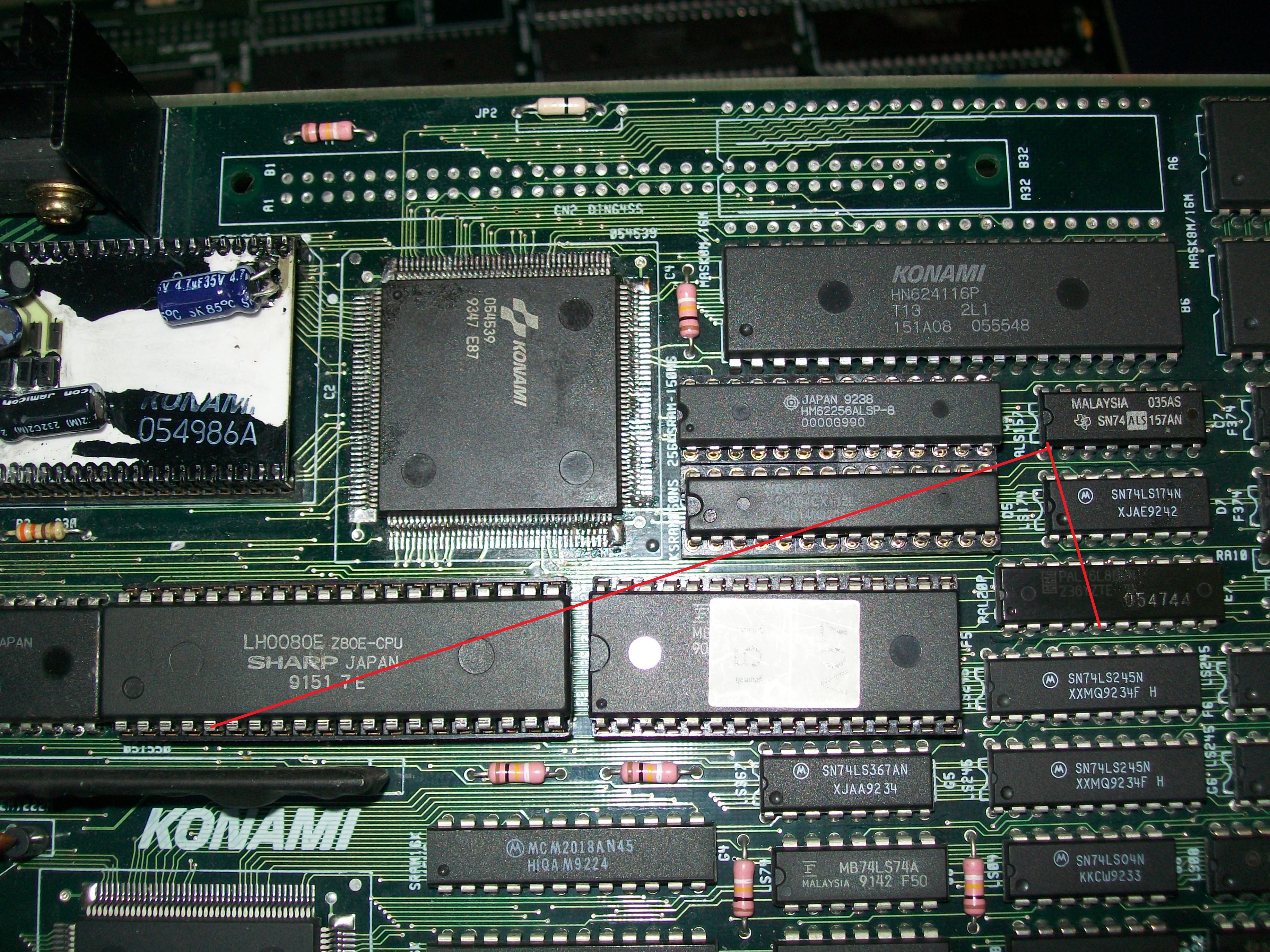
A10 and A9 were tied to ground on all 4 srams of the sprite circuit, while only A8 was floating on the sram @12C
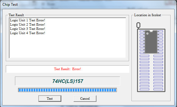
The address pins were connected to some 74LS157 and all were working correctly.
That meant the trace A8 was somewhat broken underneath.
Fortunately I had another Vimana from which I noted to which 74ls157 output A8 was connected.
After fixing the connection, the games was 100% fixed