Sep 182017
 

We all know that Konami manufactured wonderful arcade games but, you know, beautiful things are often complicated too.And surely their hardware is! This mainly because of the use of many custom chips with the most disparate functions and shape.

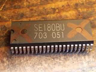
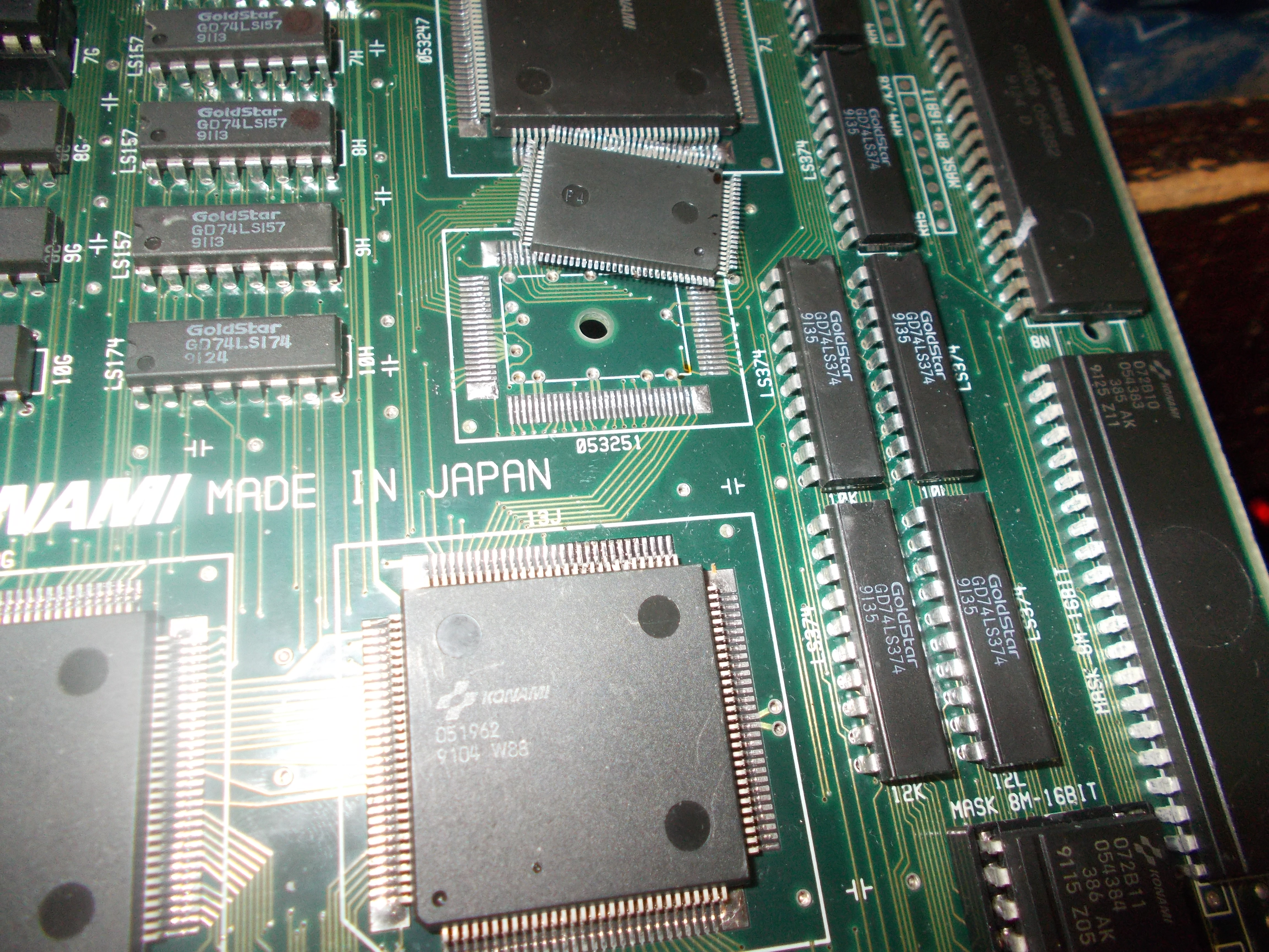
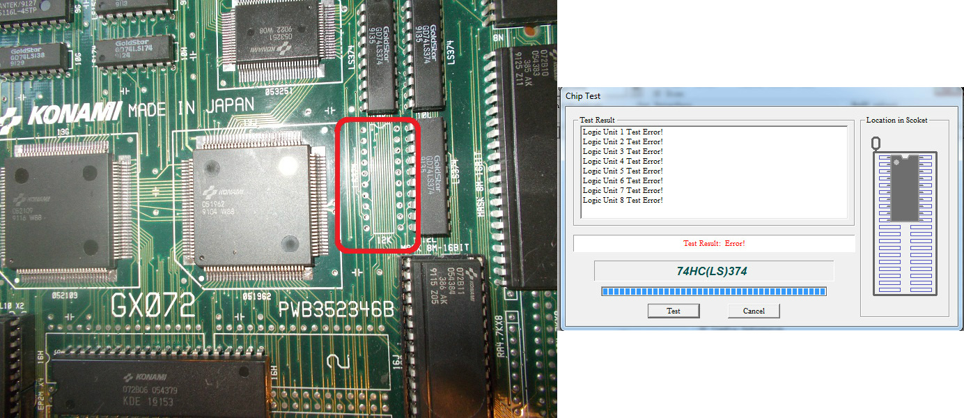
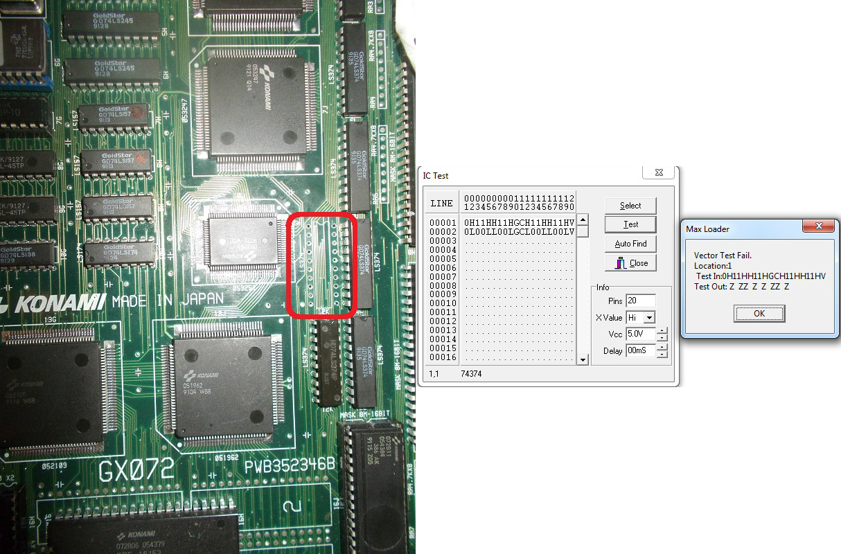
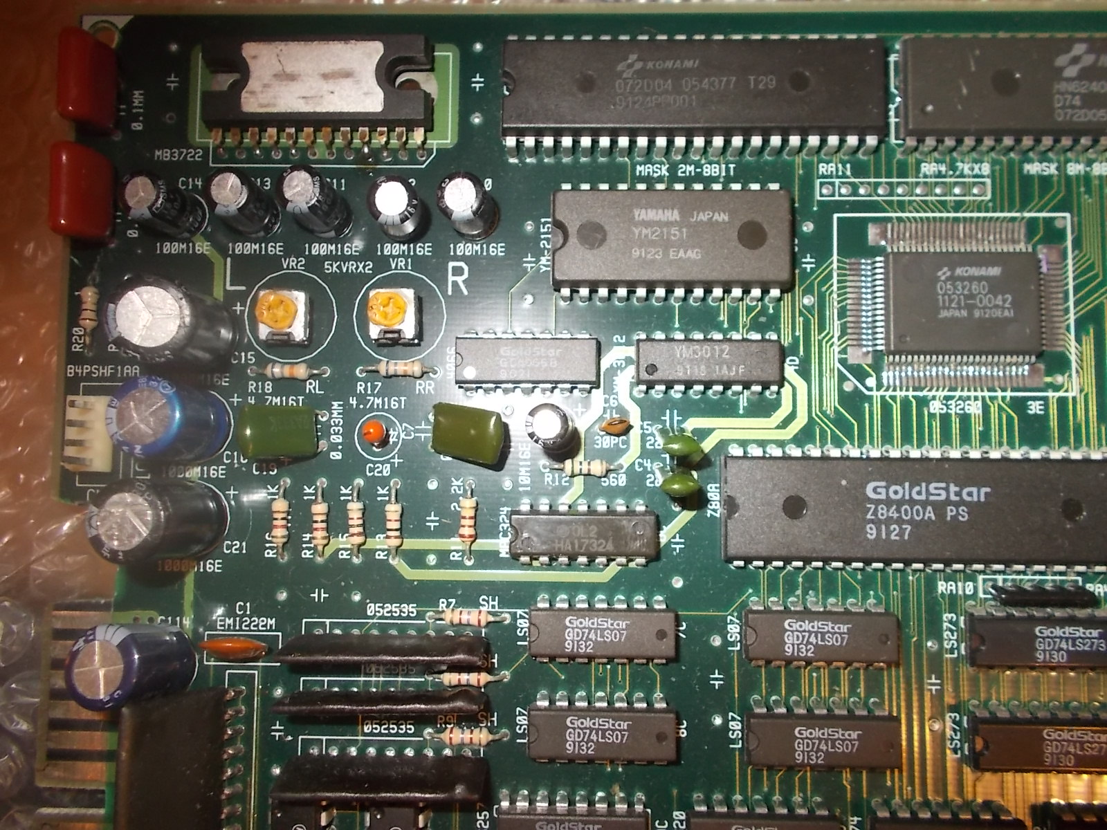
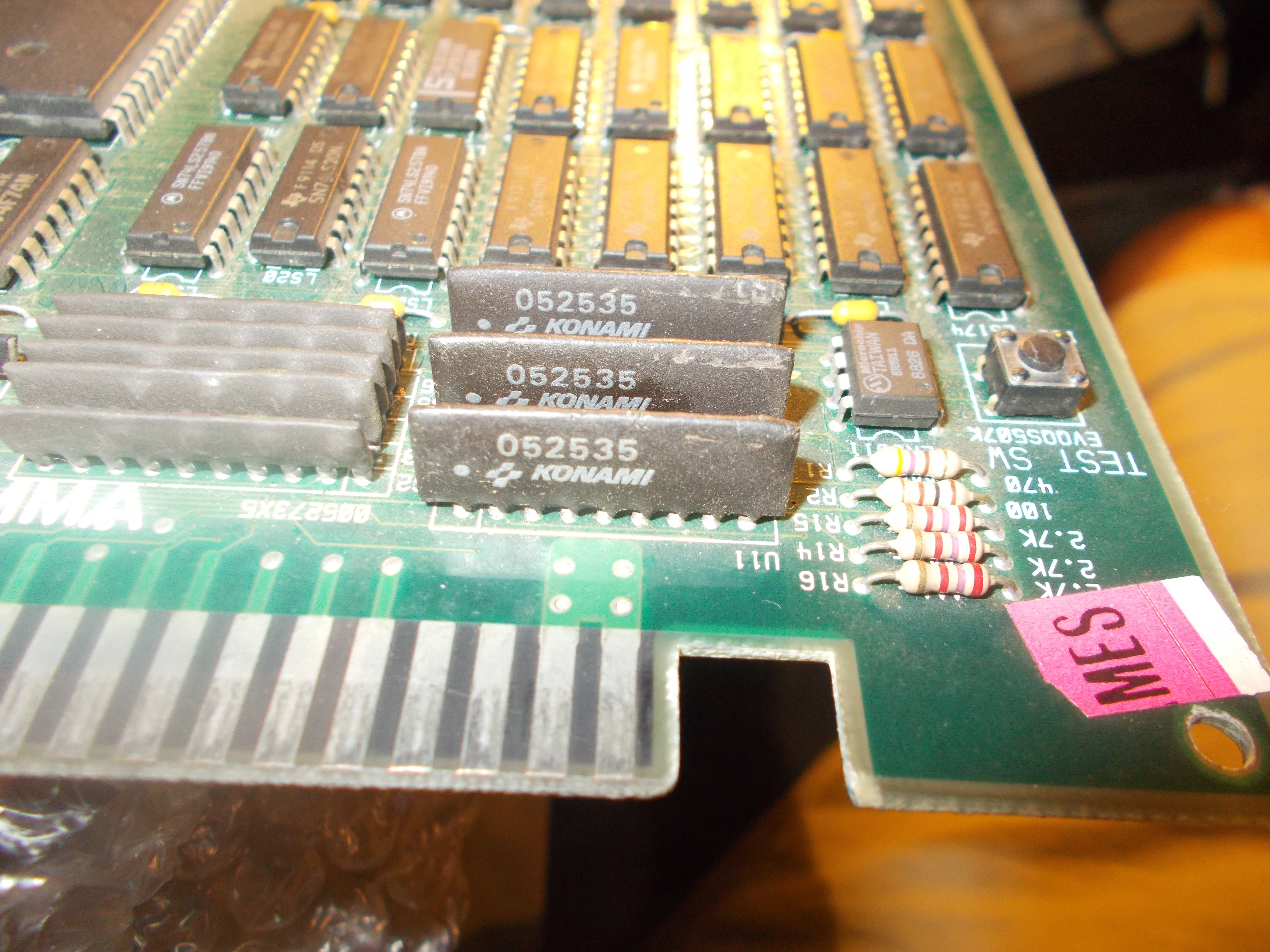
The ‘052535’ is one of them, used on countless PCBs of ’80-’90 :

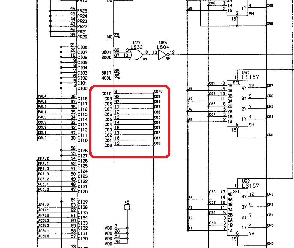
The ‘052535’ is basically a 5-bit video DAC (one for each R,G,B color) in SIL package used to convert the digital signals of the palette circuit into analog, we can see its pinout and implentation in this snippet from Lethal Enforcers schematics:

During my repairs sometimes I had to replace faulty ones so why not reproduce this part too?Perhaps someone else did it already but i did it my way.

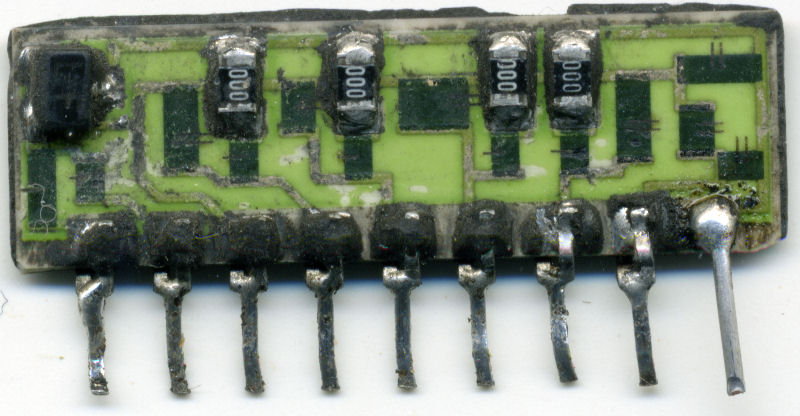
First of all I removed the black epoxy to expose the circuit and scan it :


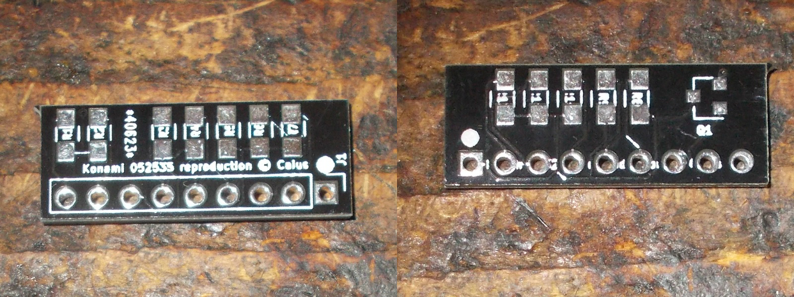
As you can see the Konami ‘052535’ is nothing more than a R-2R resistor ladder with the resistors values tipically doubled .The transistor on the left is used in final stage to amplify the analog signal adapting it to RGB arcade standard.The circuit is very simple so it took few time to draw schematics of it and route them to a PCB which ended up with more or less the same dimensions of original part:


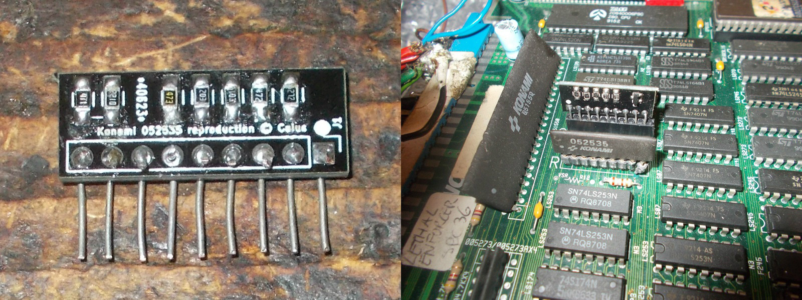
Here is the assembled reproduction, I used the legs from thru-hole components as pins which fit well in a female header:

Testing on board was successul, reproduction validated!

See you all to next project!

 Posted by at 9:22 pm
Sep 172017
 

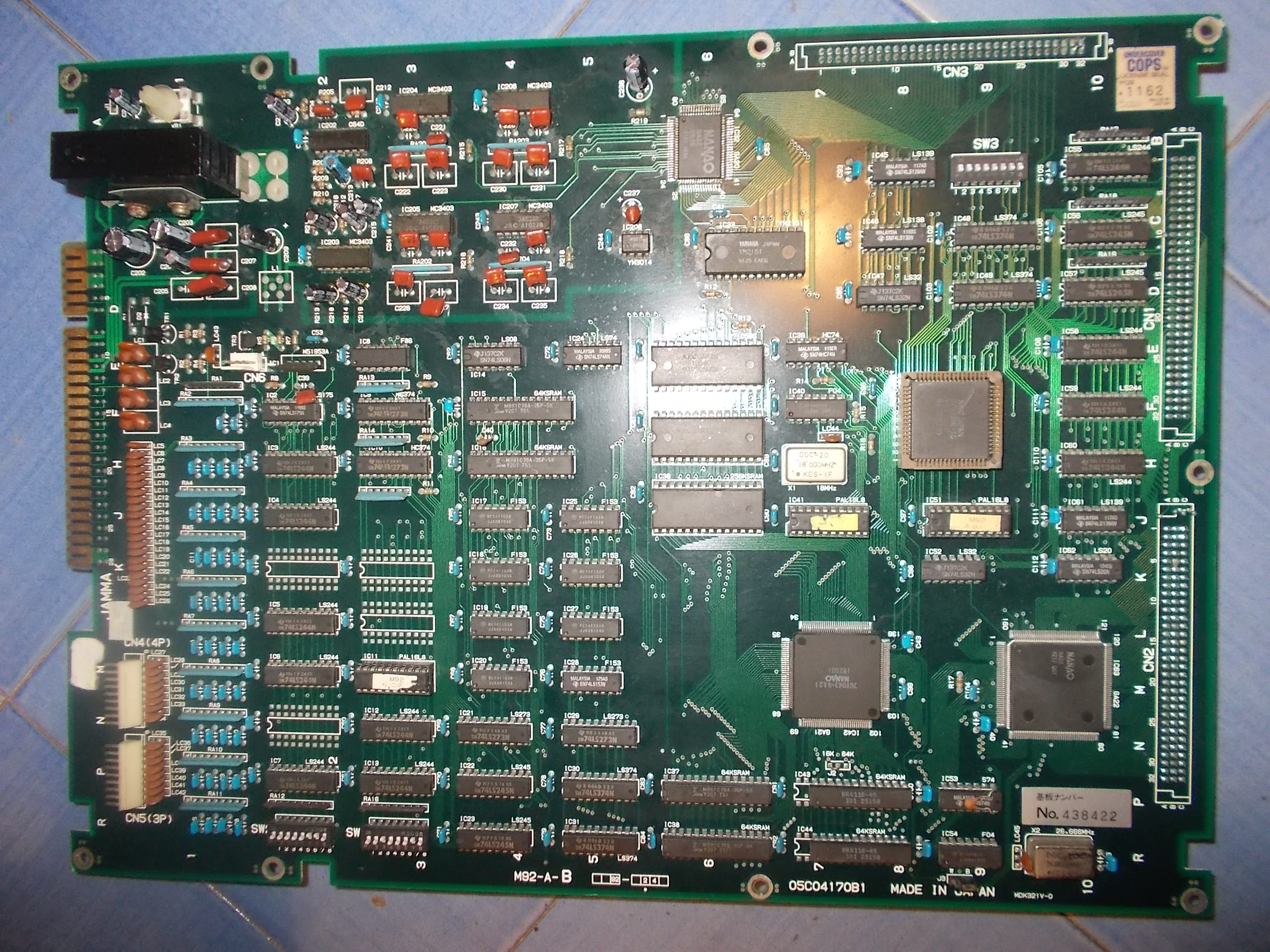
Another board from the box of faulty ones, an Irem M92 motherboard (with Undercover Cops license seal)

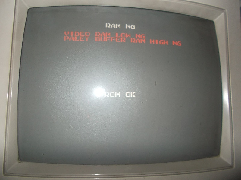
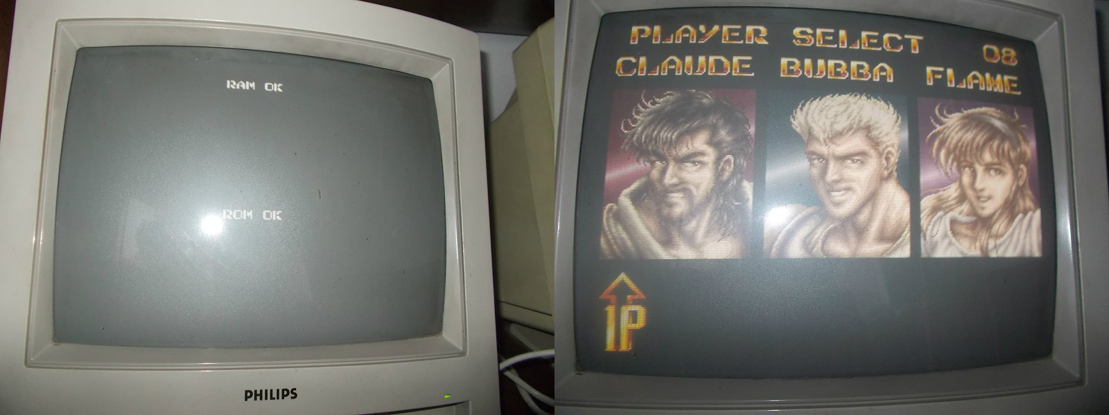
For my testing I used the ROM board from a working Undercover Cops (but I could use a whatever one).On boot I was greeted by this screen, self-test failed  reporting errors related to some RAMs 

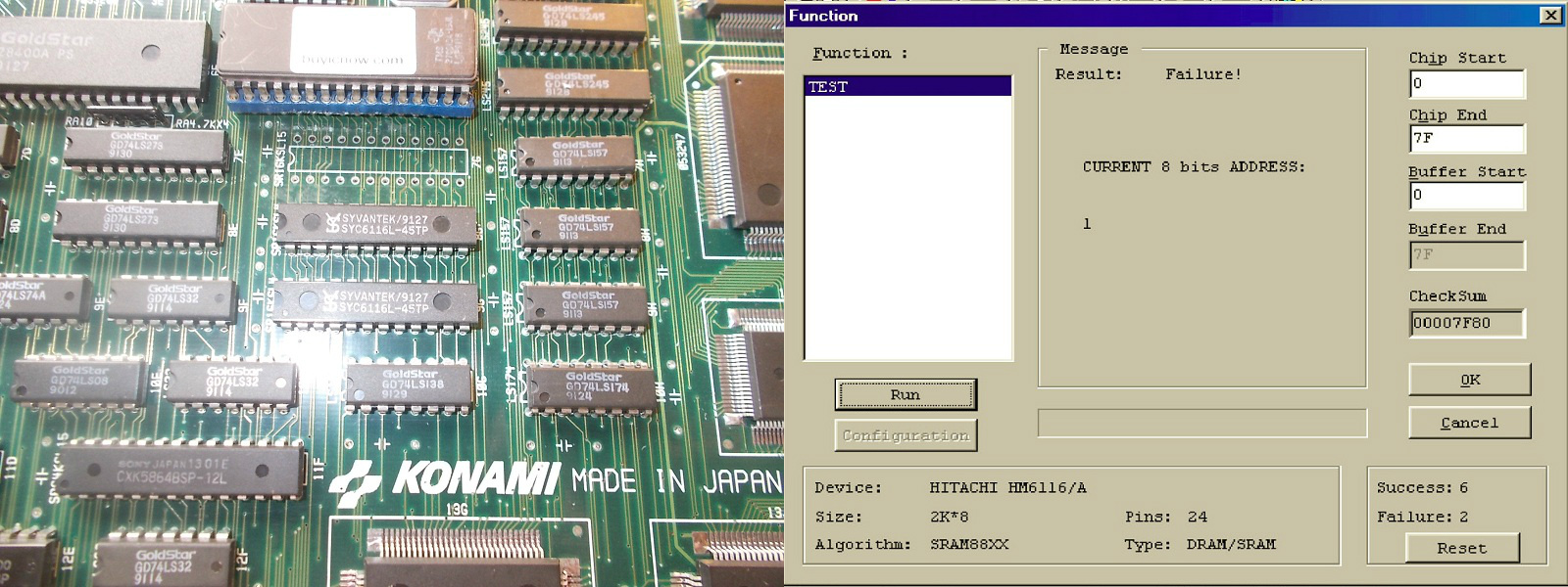
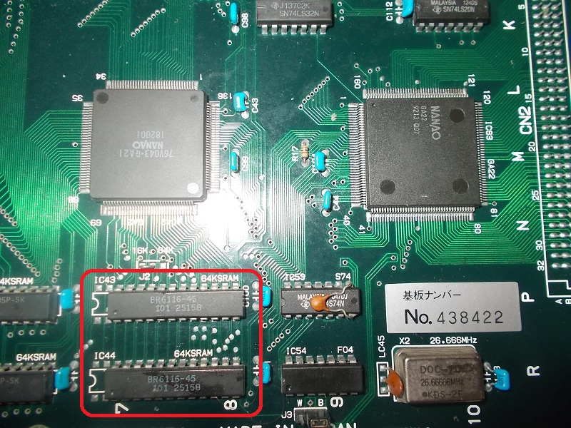
There are two  6116 SRAMs @IC43 and IC44 whose data bus is tied to the two graphics custom ASIC ‘GA22’ and ‘GA21’  :

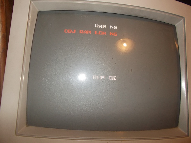
When I went to piggyback the RAMs, error changed in this:

Probing them with a scope revealed the outputs were dead on both despite the address lines were properly toggling:

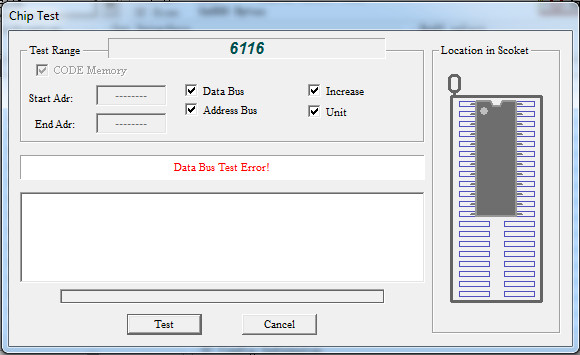
Both chips failed when tested out-of-circuit:

With good RAMs the board successfully passed the self-test and entered in game:

But sound was missing at all, I could hear only a slight buzzing noise:

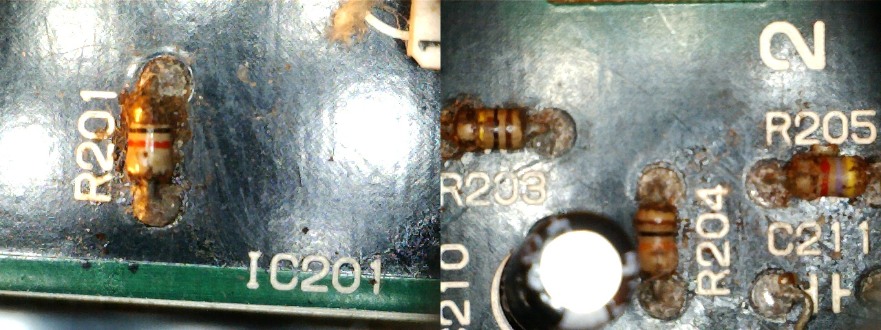
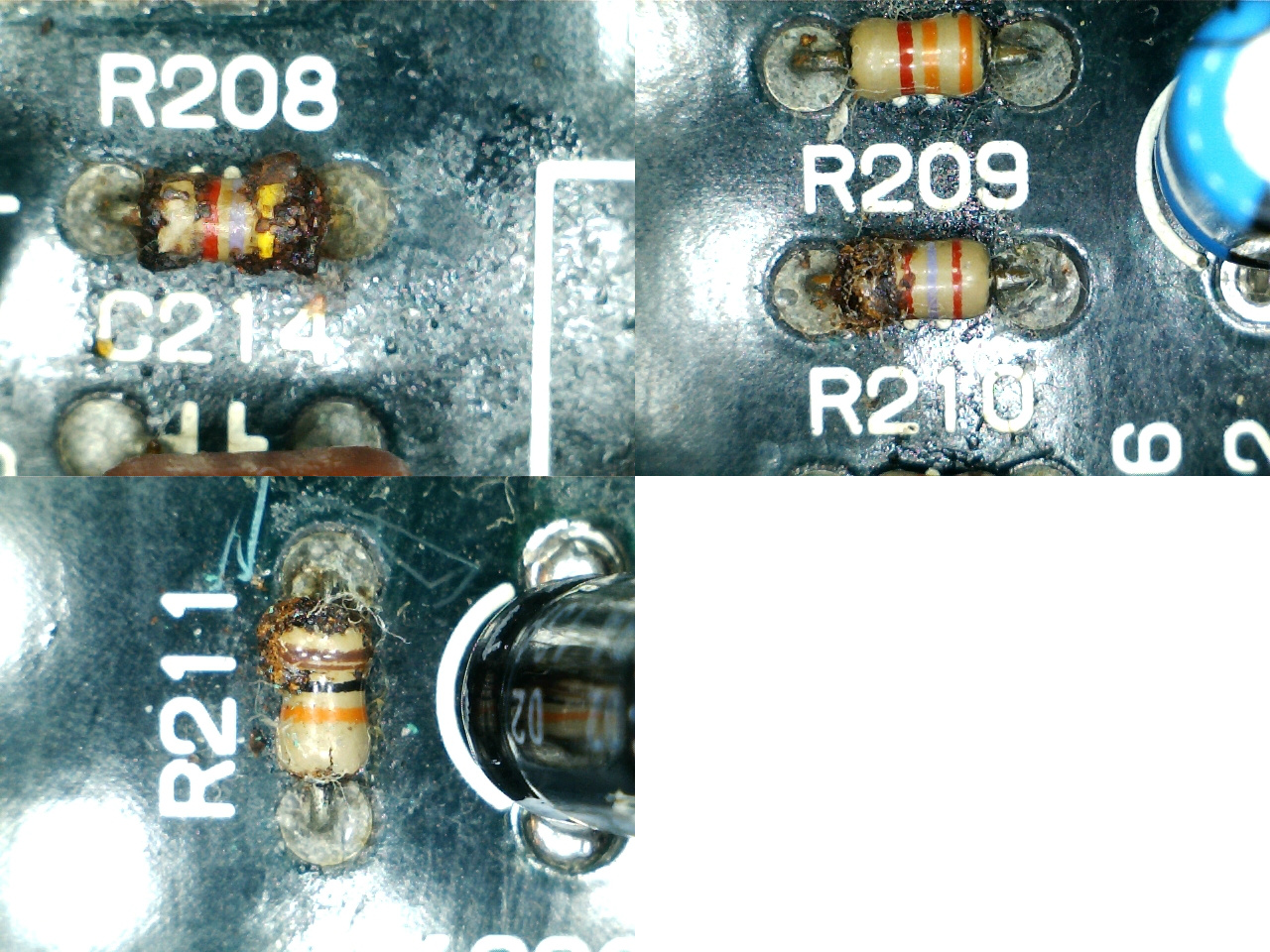
Using my audio probe I was able to verify that both FM sound and PCM samples were properly generated and then pre-amplified/mixed by OP-AMPs but signal got lost somewhere not reaching the input (pin 1) of the MB3730 amplifier.The whole audio section was previously recapped by someone so I ruled out electrolytic capacitors.But a closer inspection revealed heavy corrosion on many 1/8W resistors (probably due leakage of original ELNA capacitors), here are pictures of them taken with a microscope:

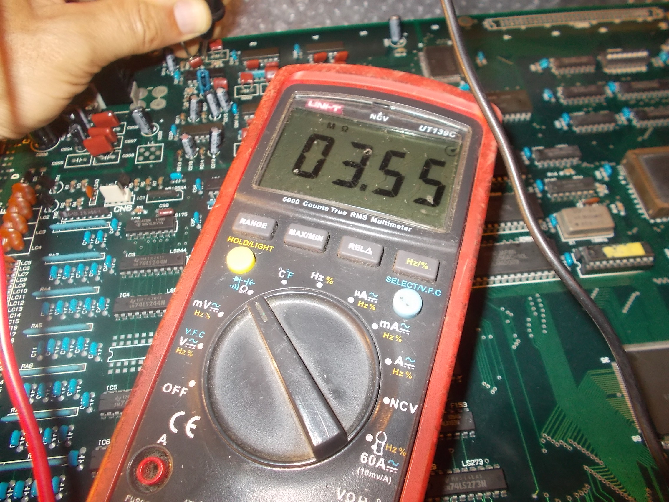
Measuring them gave me infinite resistance sign that they were open:

Here in details the bad resistors I replaced:

  • R201 –  1KOhm
  • R203 –  100KOhm
  • R205 –  4.7KOhm
  • R208 – 4.7KOhm
  • R209 – 2.7KOhm
  • R211 – 10KOhm
  • R213 – 10KOhm

This restored full sound, board 100% fixed.End of job.

 Posted by at 11:58 am
Sep 132017
 

Received some days ago a box of faulty boards for repair.There was a clean Sunset Riders PCB:

Game played fine except for sound since samples were only noise (music was fine instead):

Sound samples are stored in a 8Mbit MASK ROM @1D:

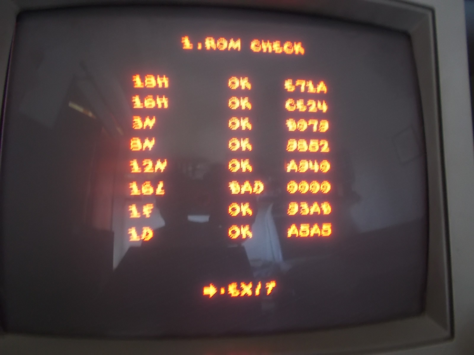
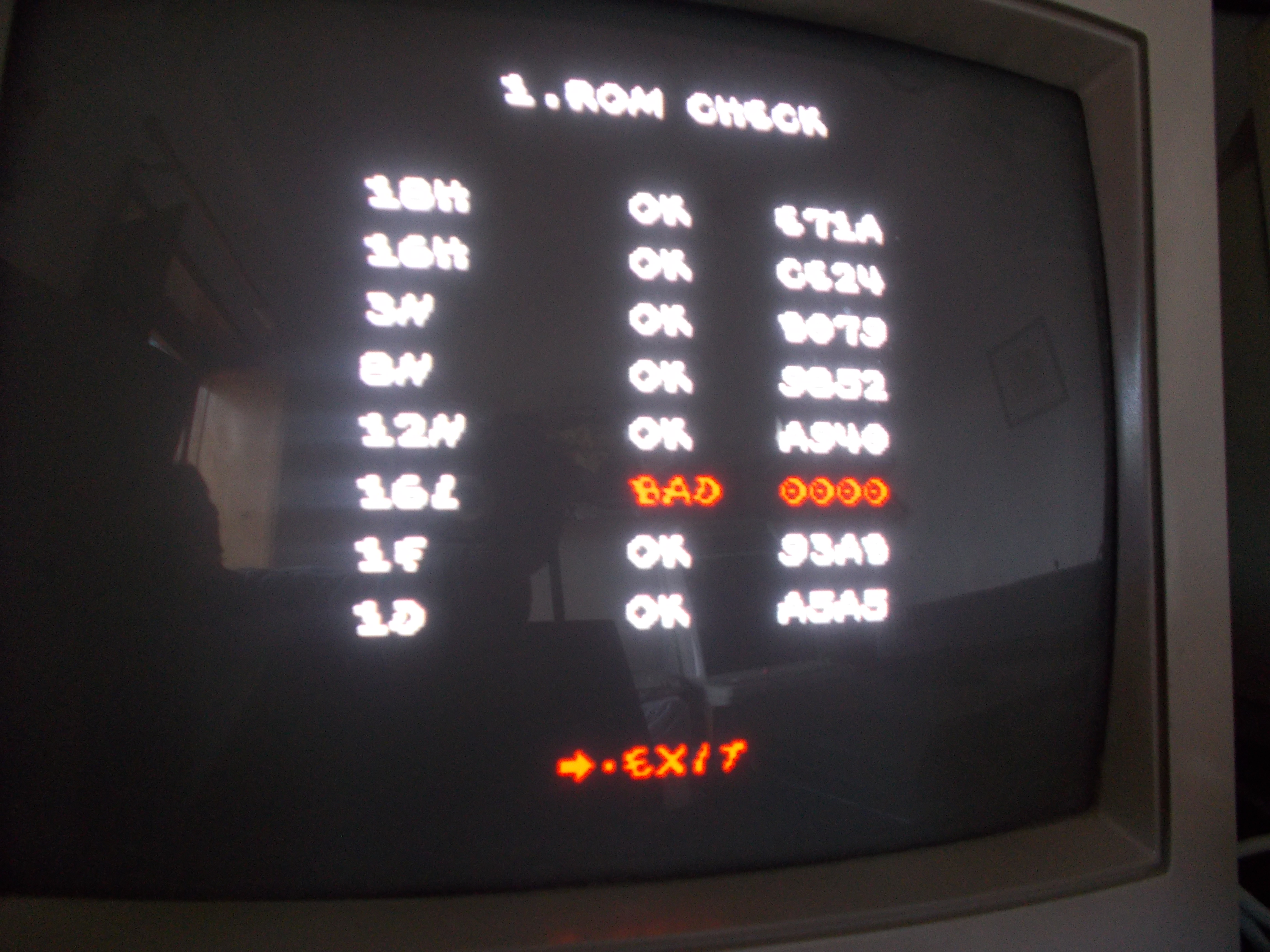
MASK ROMs check reported it as bad:

I was sure device was really bad (Konami ones are well known to be prone to failure) so I removed it :

But it turned out to be good instead since reading it ended up in a good dump and also replacing it with a programmed 27C800 EPROM had no effect .

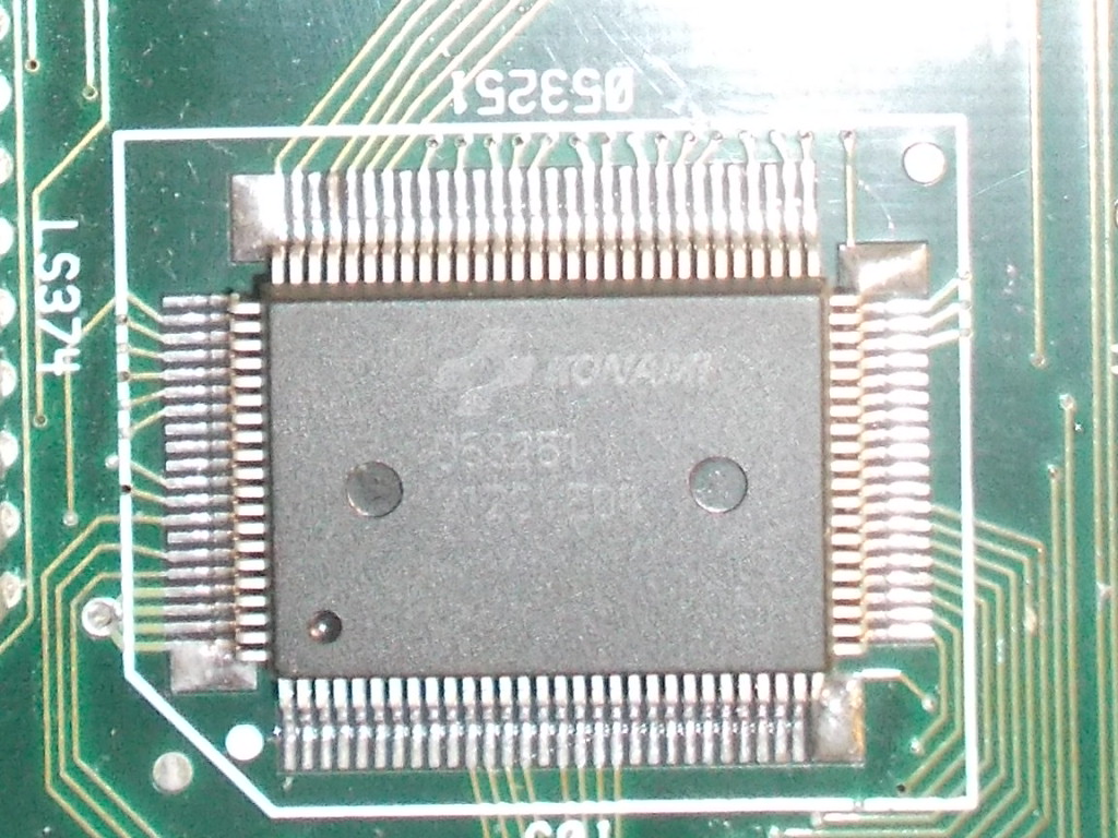
Sound samples circuit is very simple, the ASIC ‘053260’ (a custom PCM/ADPCM sound chip) addresses the MASK ROM @1D and plays its data:

No other component is direclty involved so most likely the ASIC was the culprit.I removed it :

Took the spare one from a scrap Asterix and soldered it back on my board:

Success!MASK ROMs check reported now a good device @1D hence board 100% working and fixed :

 Posted by at 6:33 pm

Bubble Bobble repair log #4

 PCB Repair Logs  Comments Off on Bubble Bobble repair log #4
Sep 122017
 

Received this original Bubble Bobble PCB for repair.Set is made of a CPU board :

and a VIDEO one :

Game played blind, no RGB output, only SYNC was present on edge connector pins.Each colors is generated by a single ‘PC040DA’ custom (a 6 bit DAC) 

Probing them revealed that pin 10 was stuck, this is the vertical blanking signal called /VBL on schematics:


Tracing back the signal  lead me to a counter 74LS163 @IC11:

Clock on its pin 2 was present but all outputs were stuck low:

The IC failed the out-of-circuit test:

I replaced it and finally had output on video but all was displayed with the only red color, green and blue were missing at all:

I checked the two involved PC040DA customs @IC85 and IC86 and found that their output pin 3 was clearly dead compared with the active one of red color:

I removed them and installed sockets:

I took the donor parts from a Rastan PCB and installed them:

Colors were restored and board 100% fixed.

P.S.

‘PC040DA’ DAC could be the next candidate for a reproduction although someone has already did it:

https://www.gamoover.net/Forums/index.php?PHPSESSID=f9cba7f099937c197dceb458d0b6a897&topic=27336.0

 Posted by at 10:16 am
Sep 112017
 

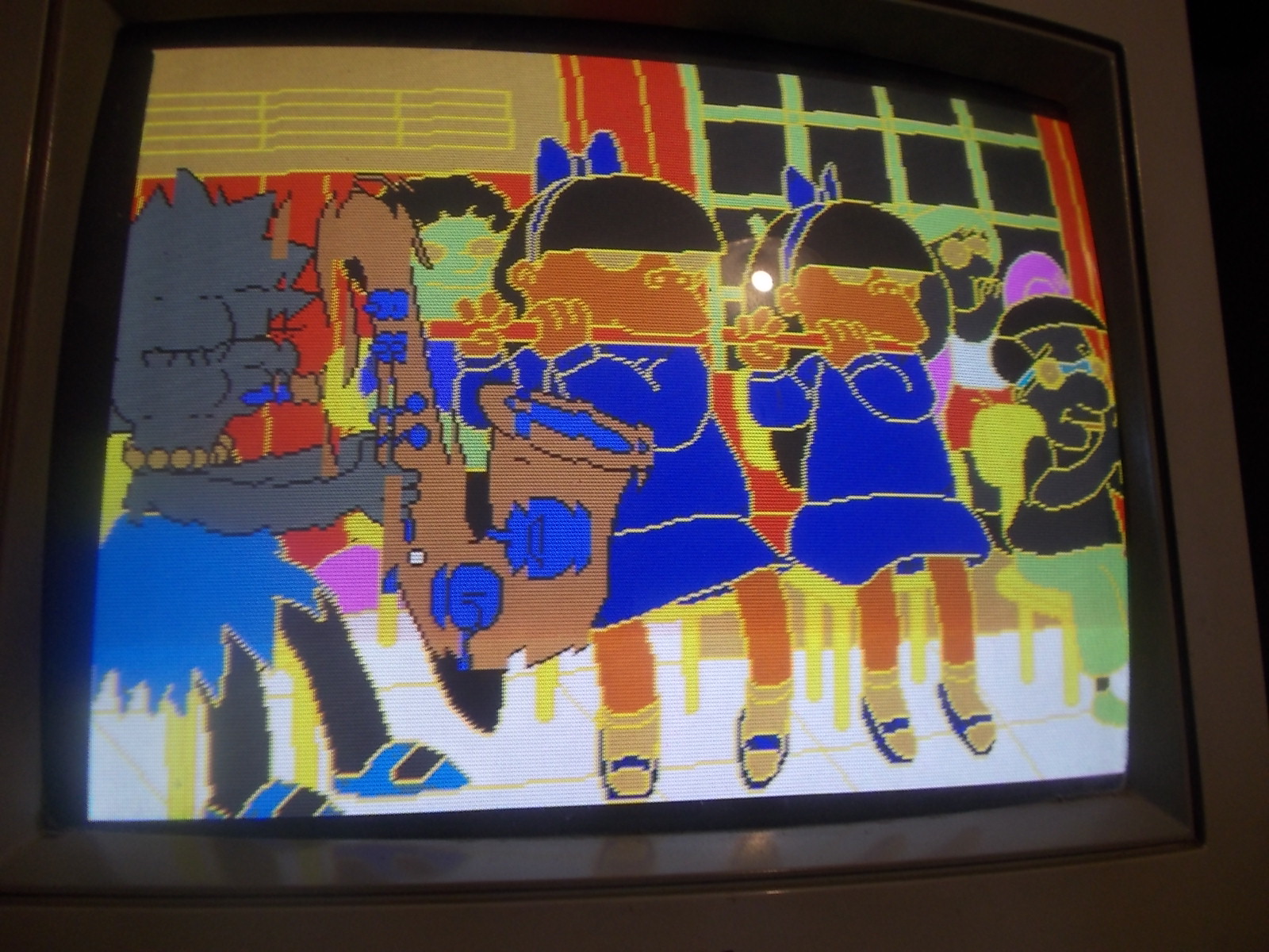
During my Hypersport’s repair I discovered a problem with the display of my Commodore 1084S monitor. Notice blue missing for “3 LONG HORSE” and “7 POLE VAULT”.

This will be the third time I’ve performed a repair on this old monitor which I’ve had since the early 90s for my Amiga 500 and 2000. At first I would suspect the AV7000 Supergun as the culprit. But subsequent tests would prove otherwise.

There’s definitely a better picture with composite or svideo from my c64 and Atari 8 bits but there seems to be a problem showing blue on the RGB input even though some blue is there ( turquoise , cyan.. etc ) in other images. Adjusting the blue gun and turning up the contrast just makes the backgrounds in Puzznic more blue. Where blue is supposed to be on the screen, it seems to not be present as though the signal were being cancelled out.  With no RGB signal to the monitor at all, it defaults to a blue screen instead of a white one.
Apologies for the sync bands.
I suspected the neck board transistors, so I pull out the one responsible for blue and tests with my multimeter show it’s fine. I even swap the transistors around to see if the problem would move to the other gun….  but it doesn’t.
I found this really good post on eab [ English Amiga Board ] by Loedown
IC502 TDA 3505 pins 12, 13, 14 are RGB in from Euro Connector /SCART, check voltages there to begin with when inputting a perfectly white screen. Then follow the voltages through to transistors TS604 – 606.
The schematic shows the analogue inputs go directly from the RGB connector to the Philips TDA3505 IC via some 100nf caps. Pins 12,13 & 14 are the input RGB signals. I measured 4.3v for red and green but 9.1v for blue. That seems a little too high for blue and the schematic indicates 4v for those signals.
I order some TDA3505s on eBay from atarifreakz and my package arrives a few weeks later.
 
Not wasting any time. I replace the chip and the picture is now perfect!
The Taito logo and blue shadow around the Puzznic logo is now visible. Notice the bricks and backgrounds are also showing up right compared with the previous screenshot.
 
I wonder if there will be a part 4 🙂