Dec 252017
 

In the past, every time I’ve undertaken a ROM hacking project i have ended up with a cluster of binary files all at varying stages of usefulness. This simple program is how I will now be working with binary file hacking.

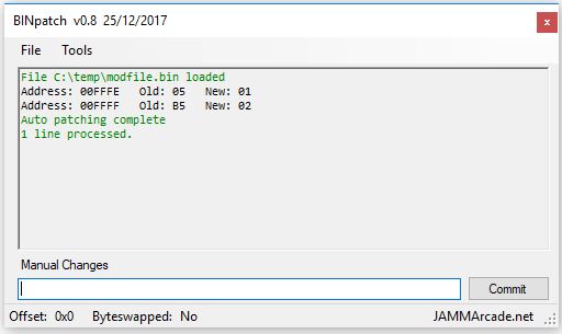
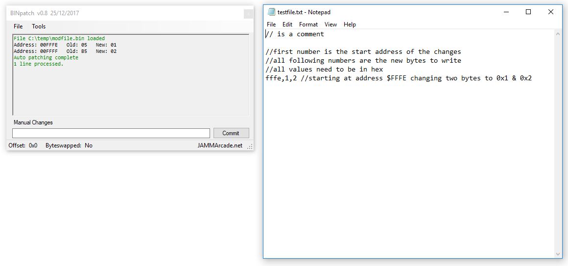
The format of the changes is really simple and can all be put together in a text file or in the program itself.

As you can see, comments are supported.
Using this I can comment the changes I make and just ‘Autopatch’ a binary file after I’m finished and if I make a mistake then I can modify the text file and reapply to the original binary.

I understand that the way I approach things is not necessarily the way most other people approach things but it might be of some use to someone else out there.

The software has a simple HEX viewer in it, can byteswap the loaded binary and also supply an offset.
The offset is relatively untested and is intended to be used if you are loading a ROM file that normally starts at, for example, address $1000 in memory space. You can apply the offset and write values to the correct addresses. If in doubt then just avoid this altogether as it will cause problems and cant really do any error checking.

Merry Chistmas

 Posted by at 3:57 pm

Rolling Thunder repair log #3

 PCB Repair Logs  Comments Off on Rolling Thunder repair log #3
Dec 242017
 

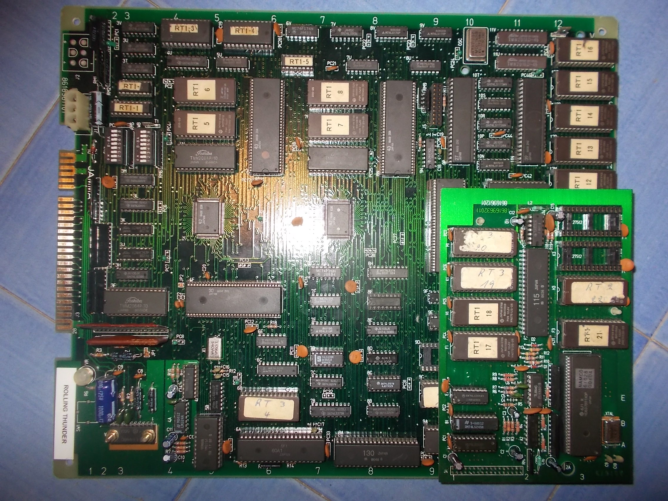
Received from Spain this faulty Rolling Thunder PCB for repair:

Board was not booting stuck on a static garbabe screen with some background sound noise (which seems a common issue on this PCB)

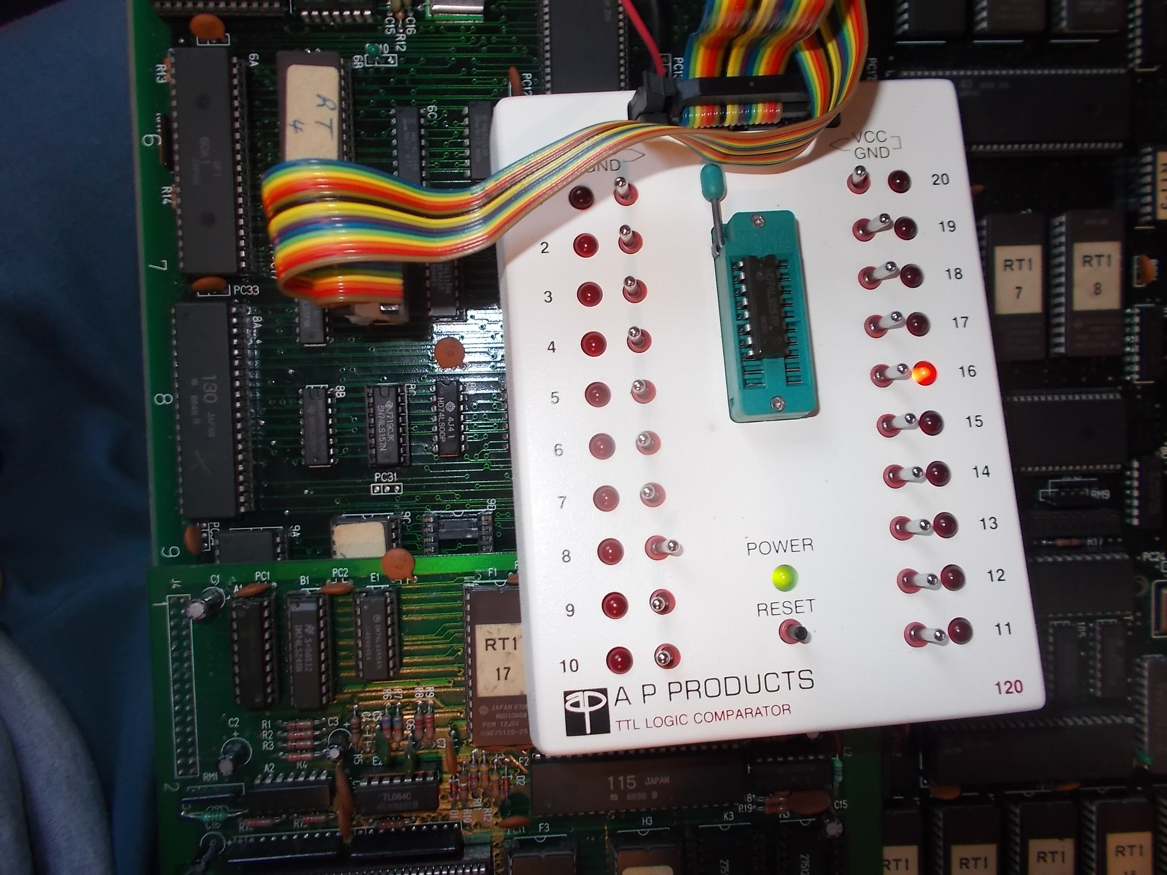
After ruled out all the custom ICs, few was left to test.The background sound noise very likely  suggested a problem in the digital sound circuit that on this hardware must be working for proper operation of the whole system.Probing this circuit with a logic comparator revealed nothing abnormal until I tested a 74LS257 @7C, I was warned about a problem on its output pin 12:


Also comparing with a scope this ouput with the one of the reference IC gave discrepancies, signal was not properly toggling (good on left of the below picture)

Looking at schematics pin 12 of this 74LS257 outputs the address line ‘A0′ to a 6264 static RAM @3F tied to the custom ’30’ which controls the sound system:

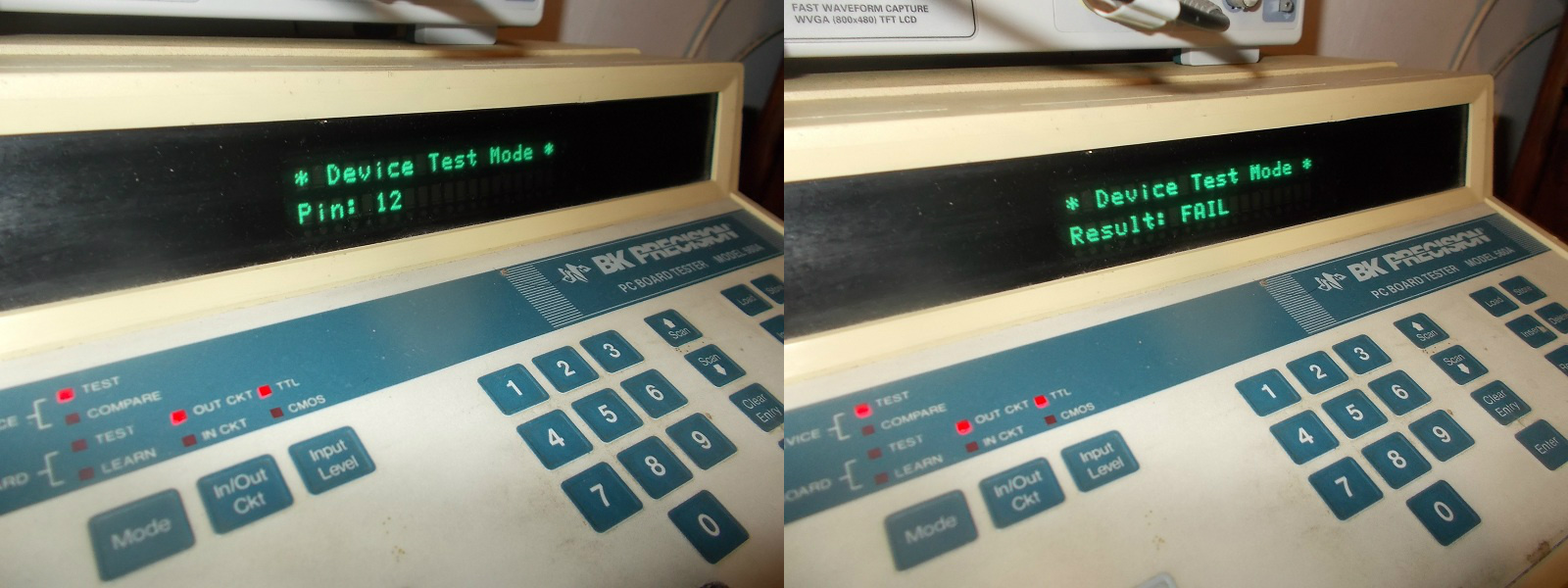
Sure enough I removed the TTL which failed the out-of-circuit exactly in pin 12:

After replaced the TTL the board successfully booted, no further issue were found so 100% fixed.


 Posted by at 4:23 pm

New dump of KD29B added

 PAL Updates  Comments Off on New dump of KD29B added
Dec 212017
 

Today I’ve added a new dump of the KD29B PAL from King of Dragons on CPS1.
The original dump was taken from a seemingly unlocked device but was dumped as a GAL16V8 instead of a PAL!6L8 which may have caused issues.
Anyway, I’ve recently had the opportunity to study this chip and have what I believe to be a more accurate version.

 Posted by at 4:06 pm

Dogyuun repair log #1

 PCB Repair Logs  Comments Off on Dogyuun repair log #1
Dec 192017
 

Got from Portugal this almost mint but not working Dogyuun PCB, a shoot ’em up released by Toaplan in 1992:

On power up, after the system got initialized, board sat on a black screen.Main 68000 CPU was halted at this point,no sign of activity on all busses and control lines:

Usually this happens when a device (most of times RAMs) in the CPU address space doesn’t answer to initial check.So I went to probe RAMs and found that the two Mitsubishi M5M5178 @U46-U47 (8k x 8bit static RAM compatible with 6264) had /OE and /WE lines stuck (they are addessed by one of the GP9001 ASIC so the are VIDEO RAMs) 

When I went to piggyback the one @U47 the board successfully booted and entered in game:

The chip obvioulsy failed the out-of-circuit test:

The game was fully playable but while testing I noticed some of the player 2 inputs didn’t work, in particular LEFT RIGHT, BUTTON 1 and 2 were responding at same time when one of them was activated.This can be clearly seen in the input check of TEST mode:

Checking with a logic probe the relevant pins of the  JAMMA edge connector revealed that they were floating when usually they must stay in HIGH state when not activated (and then LOW when input is activated).Pull-up resitors or resistors array are used most of times to keep the inputs in HIGH state.When I went to check with a multimeter the 4.7K array @RM7 I found no reading from pin 5 onwards :

So it was most likely internally cracked.Indeed, once removed, it fell off in two parts:

Fitting a good one cured the issue.Board 100% fixed.


 Posted by at 5:01 pm

Dangerous Curves PALs added

 PAL Updates  Comments Off on Dangerous Curves PALs added
Dec 102017
 

Muddymusic sent me a Dangerous Curves PCB which has a load of unlocked PALCE16V8 devices on it.
I dumped them all using my programmer.
The PCB is a non worker so I cannot test these but they are assumed working at this point.

Thanks to my good friend Muddymusic for this

 Posted by at 12:06 pm