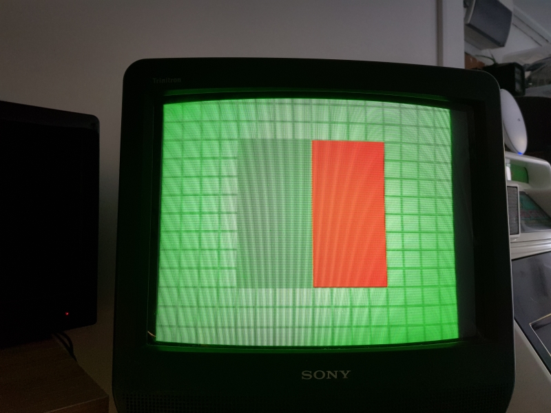
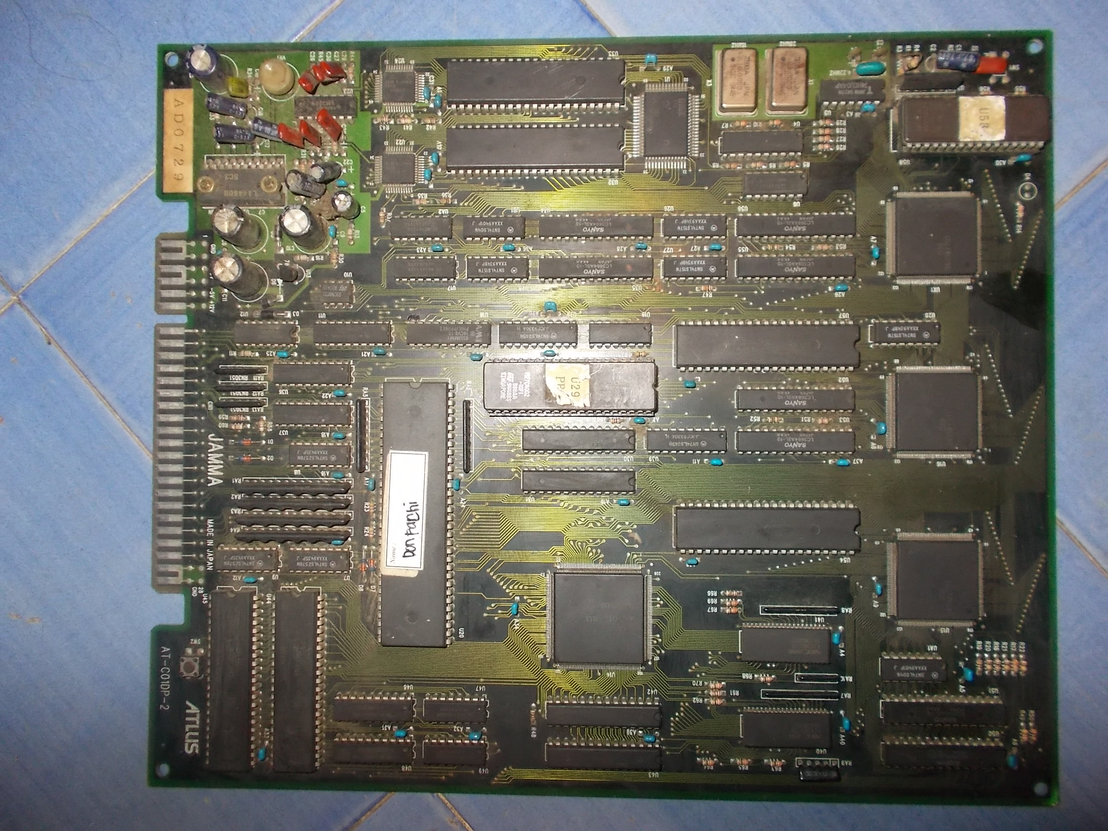
Received from Germany this faulty DonPachi PCB for repair:
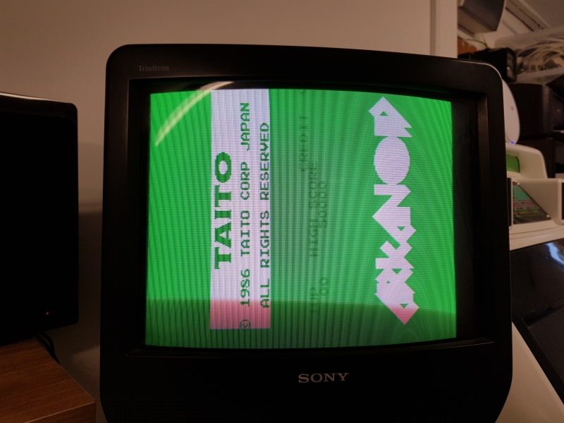
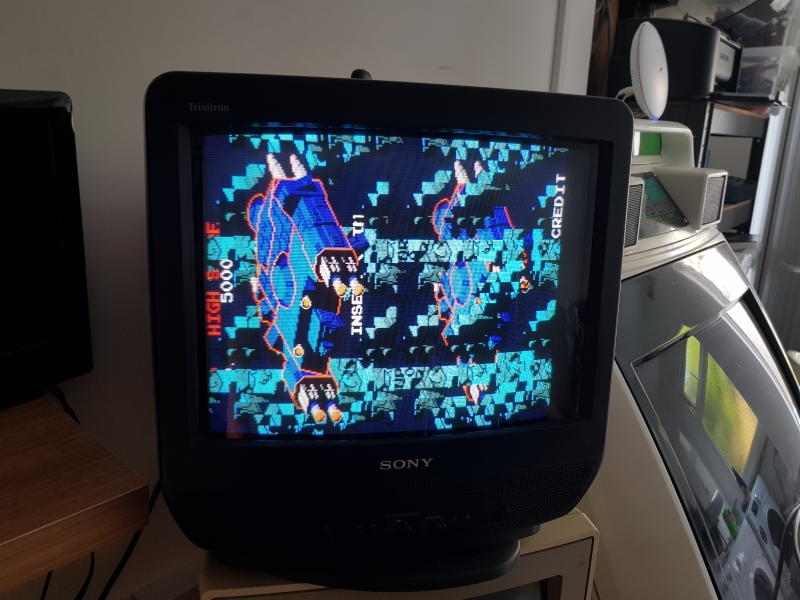
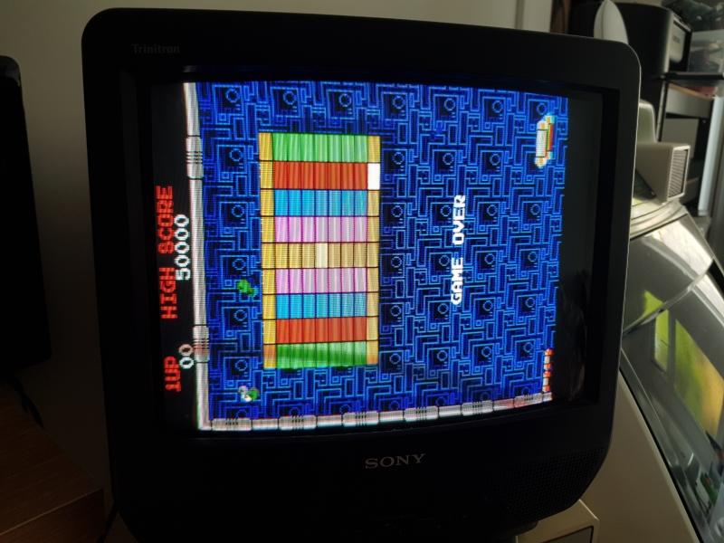
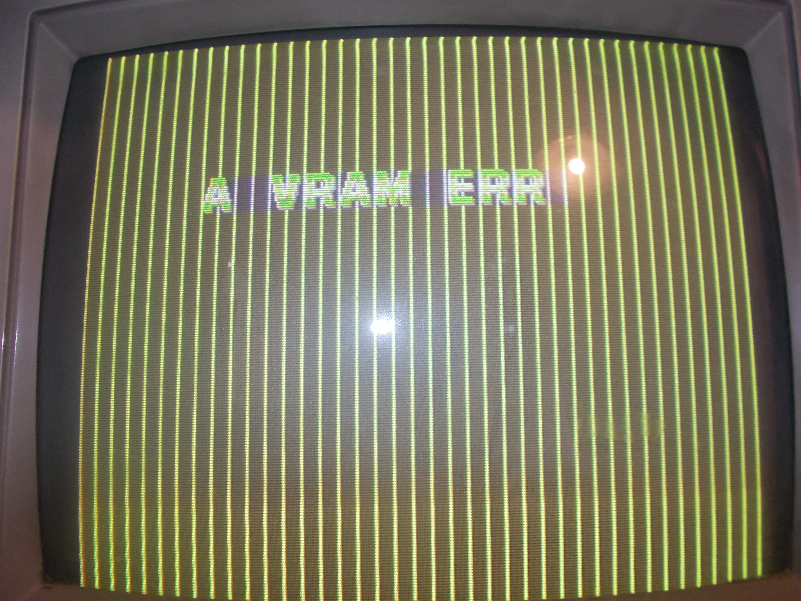
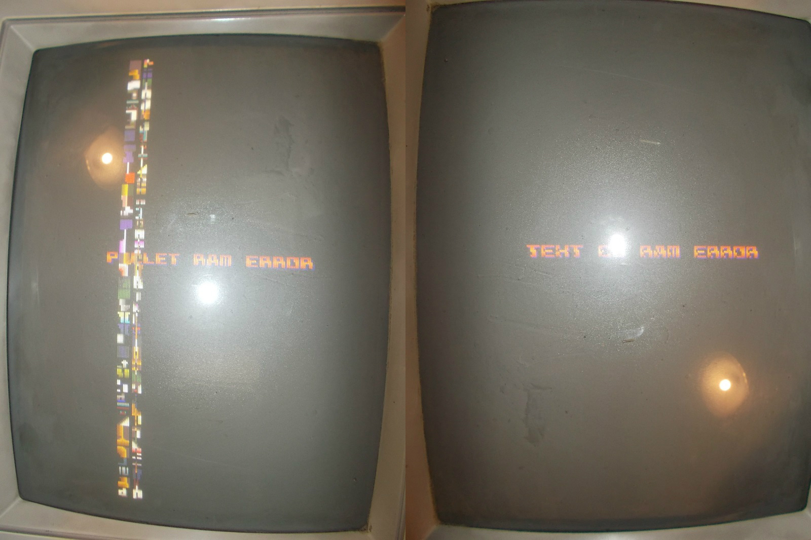
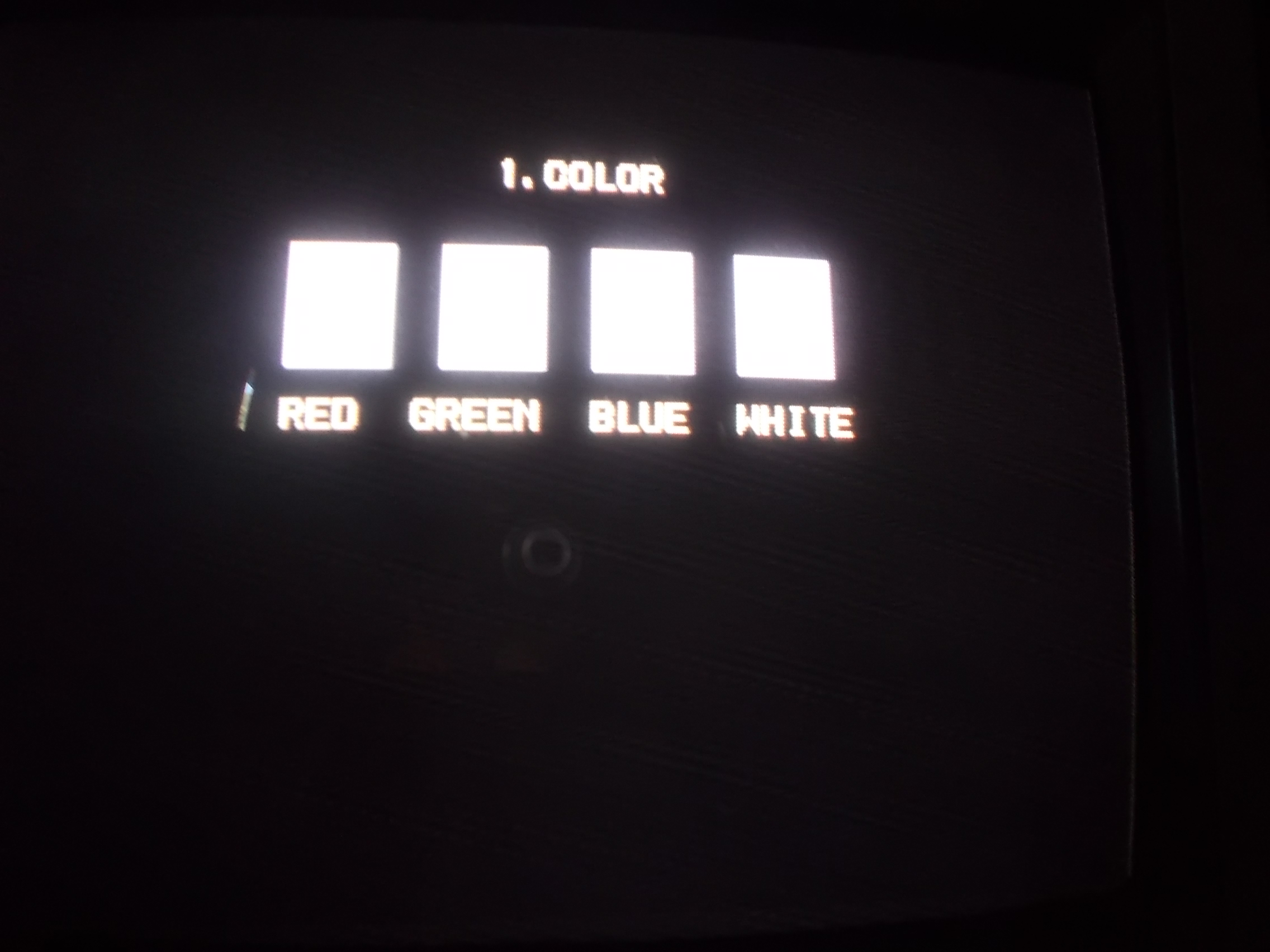
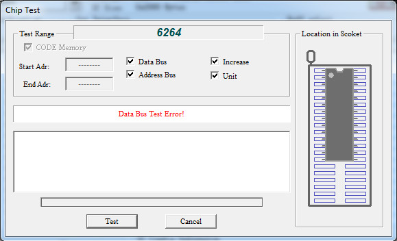
Board played almost ‘blind’, most of graphics was missing, only some corrupted text was visible:
According to MAME source there are three layers of graphics:
ROM_REGION( 0x100000, “layer0”, 0 ) /* Layer 0 */
ROM_LOAD( “atdp.u54”, 0x000000, 0x100000, CRC(6bda6b66) SHA1(6472e6706505bac17484fb8bf4e8922ced4adf63) )ROM_REGION( 0x100000, “layer1”, 0 ) /* Layer 1 */
ROM_LOAD( “atdp.u57”, 0x000000, 0x100000, CRC(0a0e72b9) SHA1(997e8253777e7acca5a1c0c4026e78eecc122d5d) )ROM_REGION( 0x040000, “layer2”, 0 ) /* Text / Character Layer */
ROM_LOAD( “text.u58”, 0x000000, 0x040000, CRC(5dba06e7) SHA1(f9dab7f6c732a683fddb4cae090a875b3962332b) )
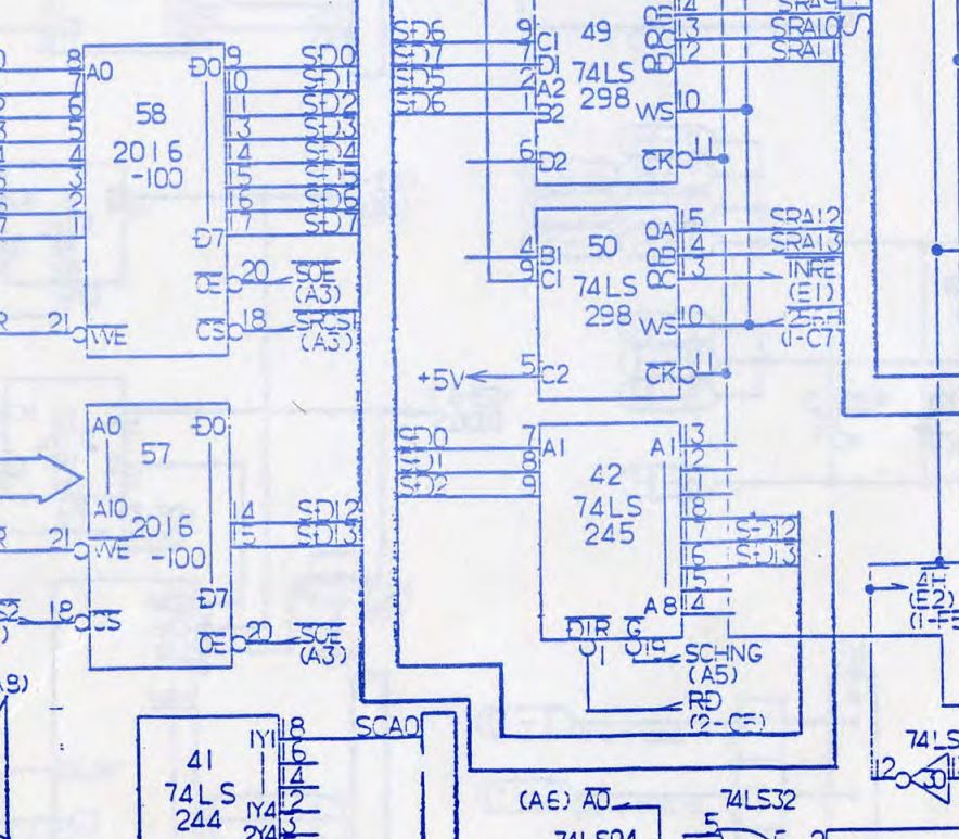
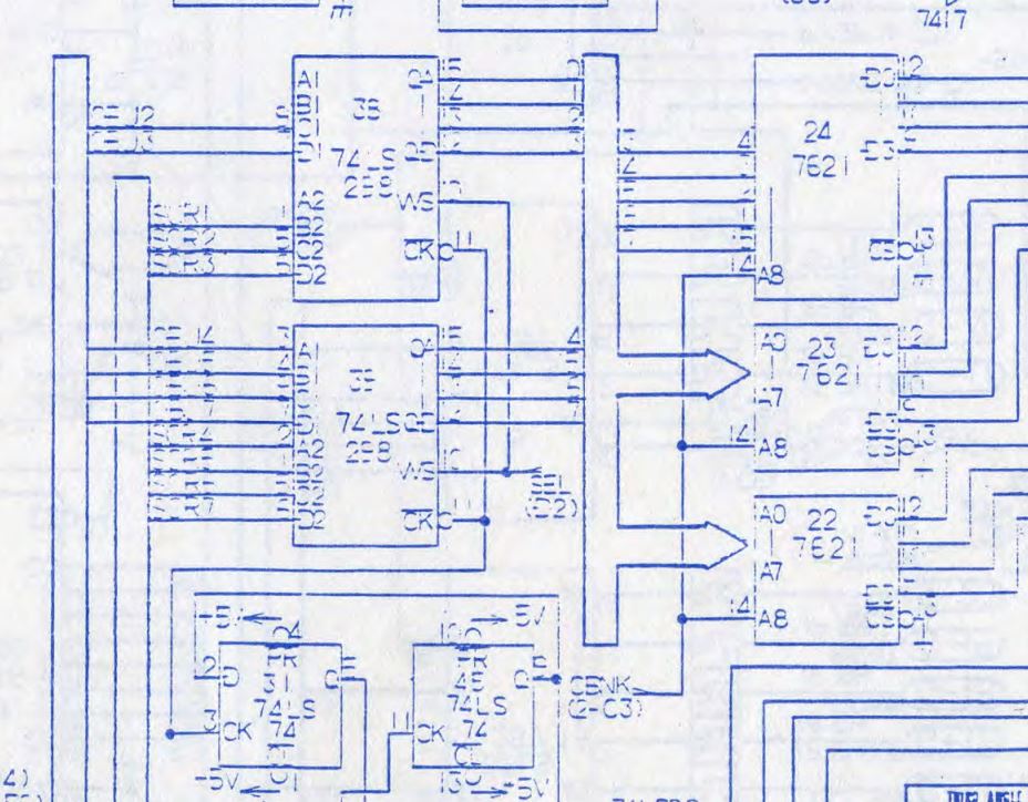
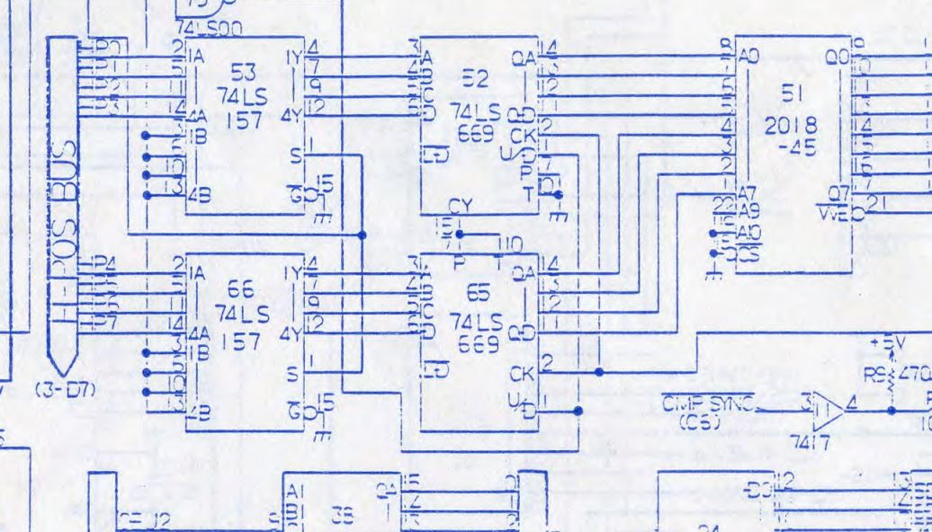
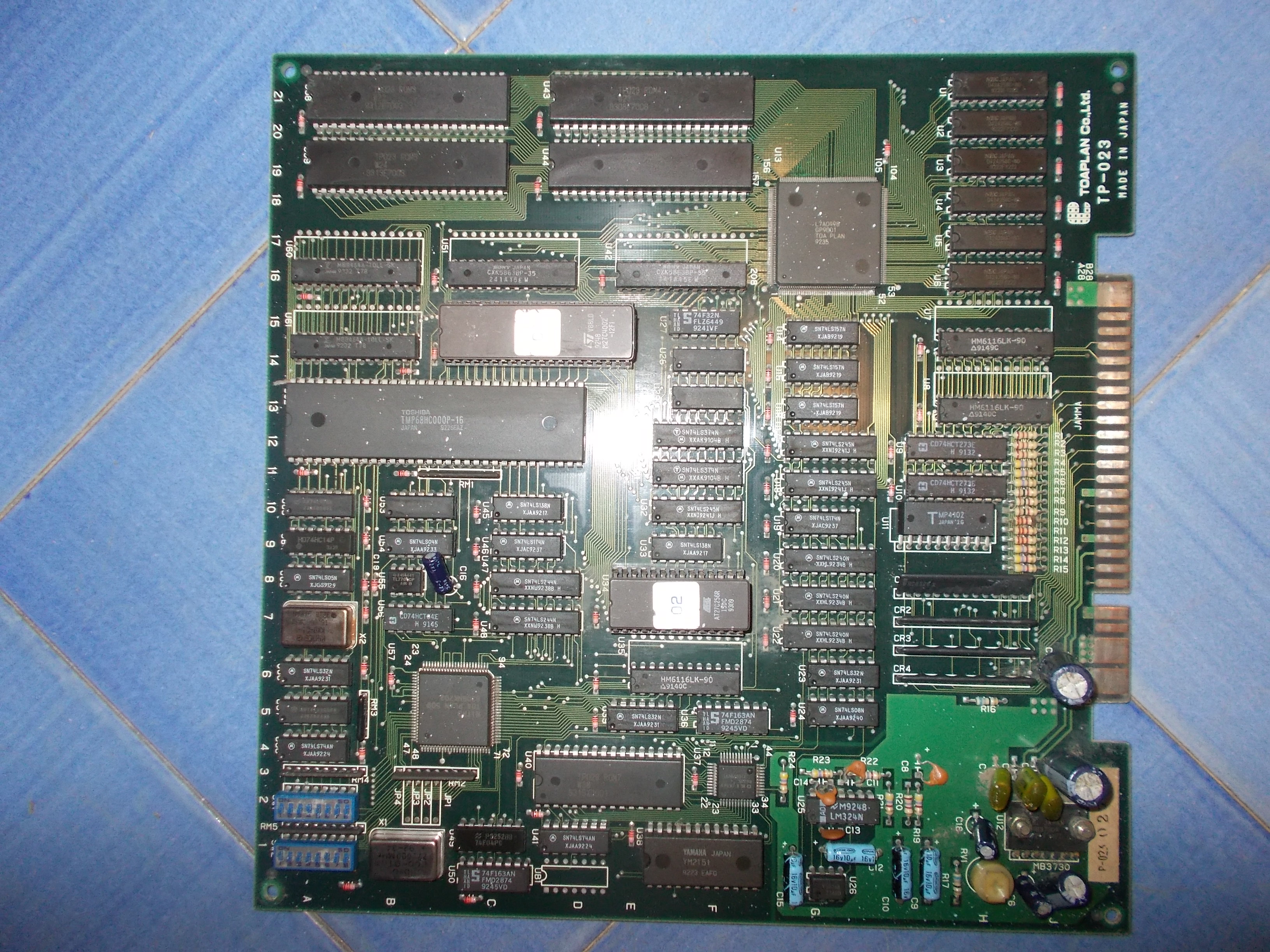
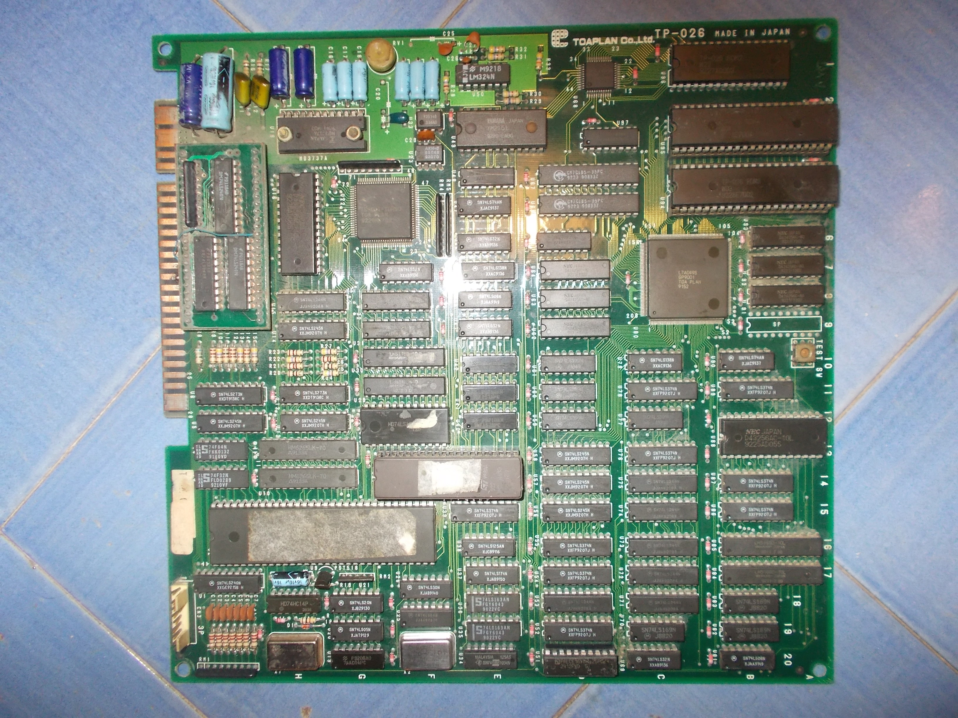
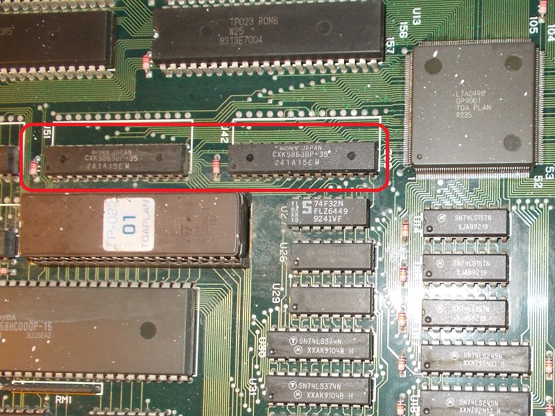
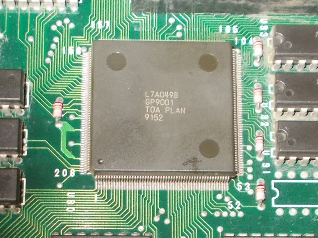
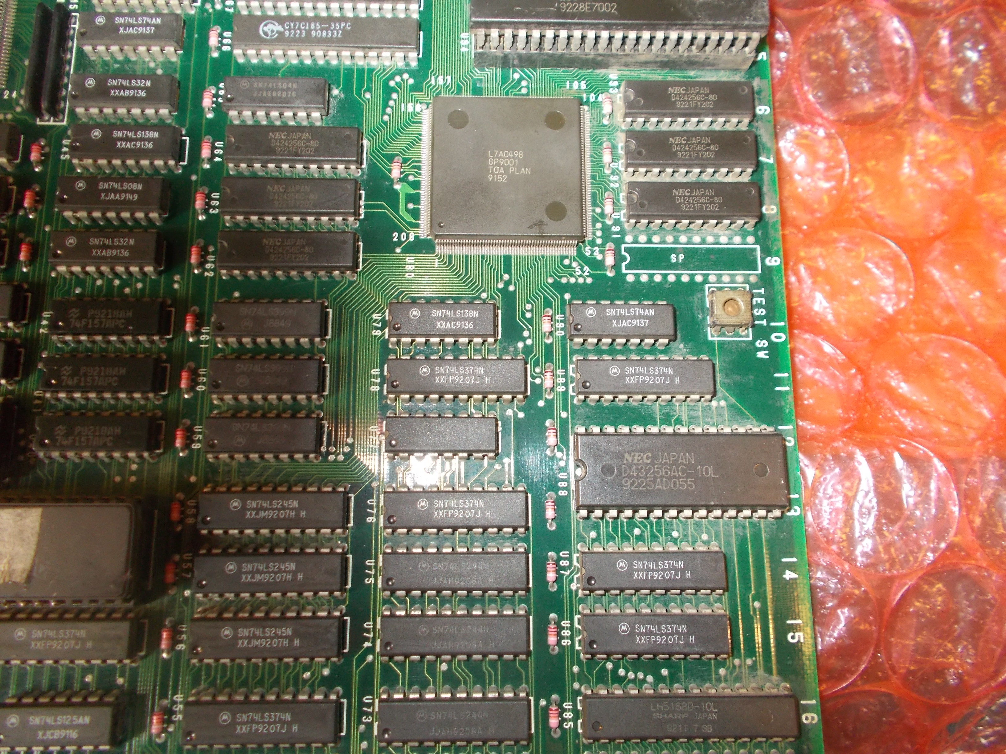
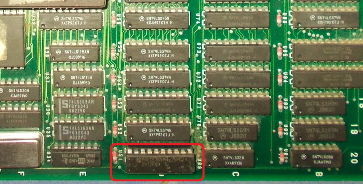
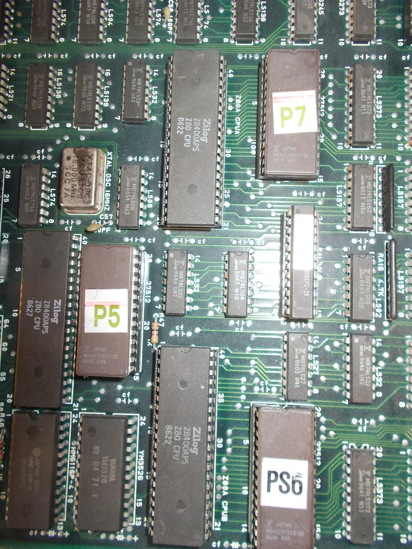
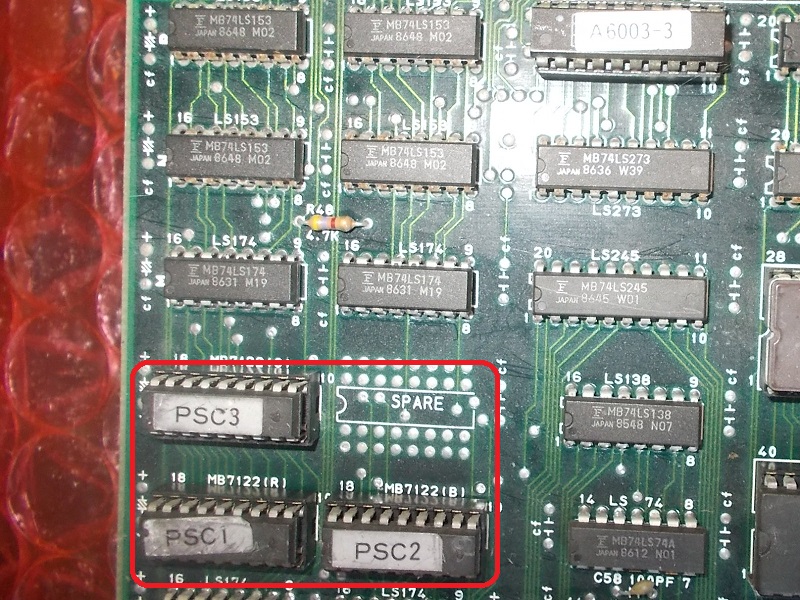
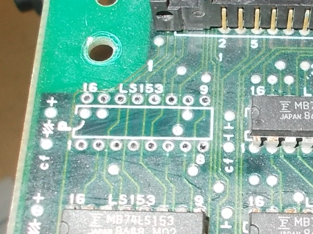
I translated this info on hardware and figured out the relevant circuit of each layer:
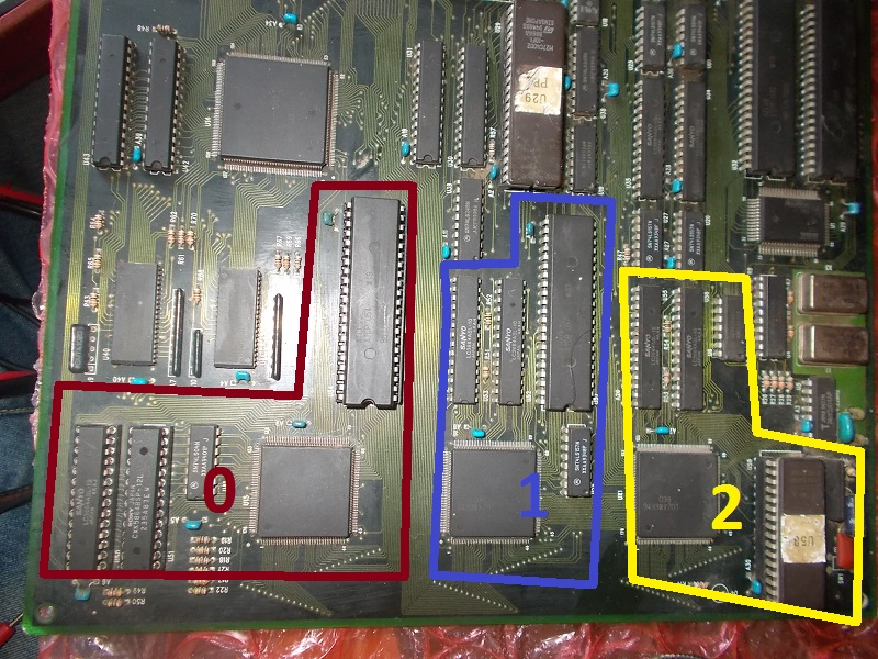
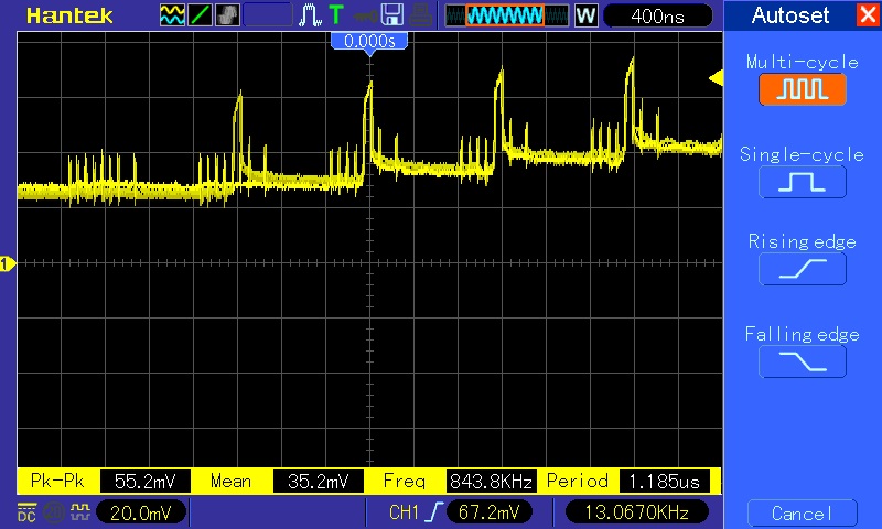
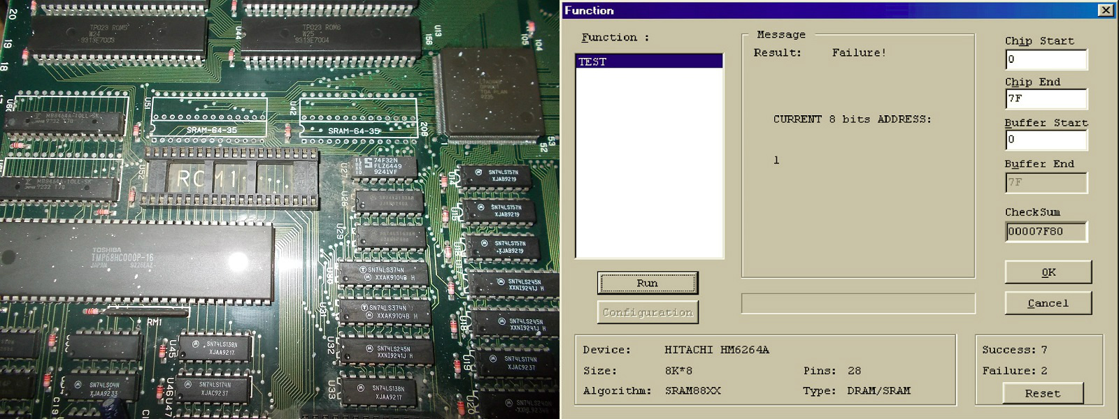
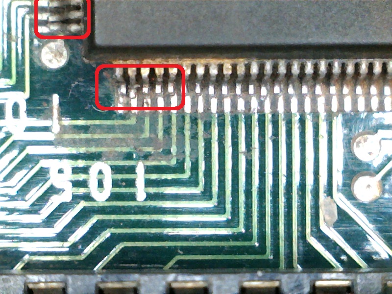
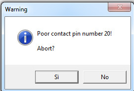
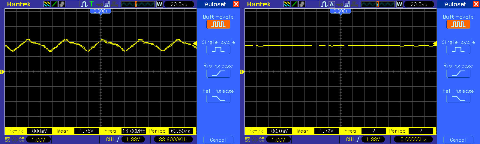
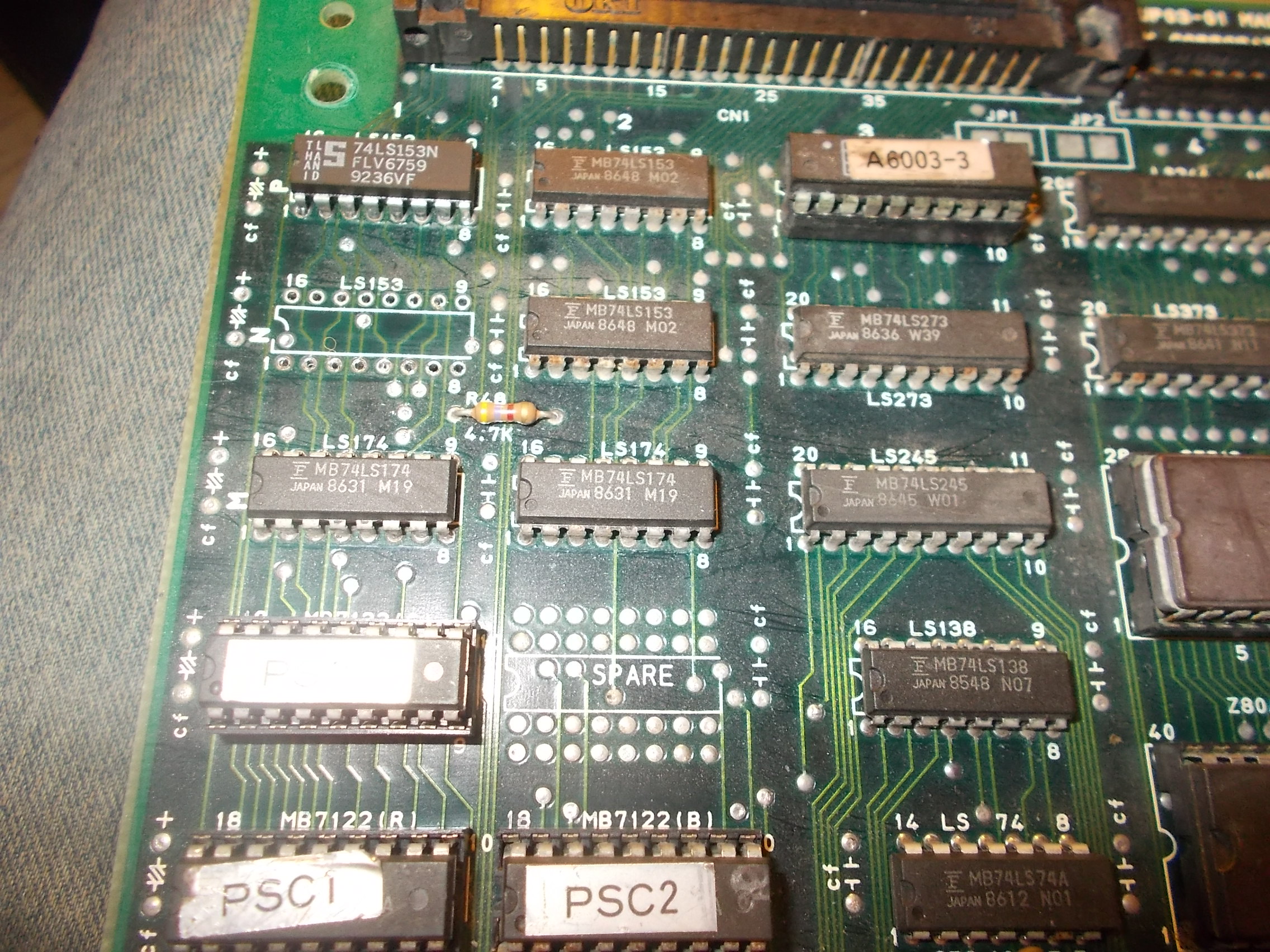
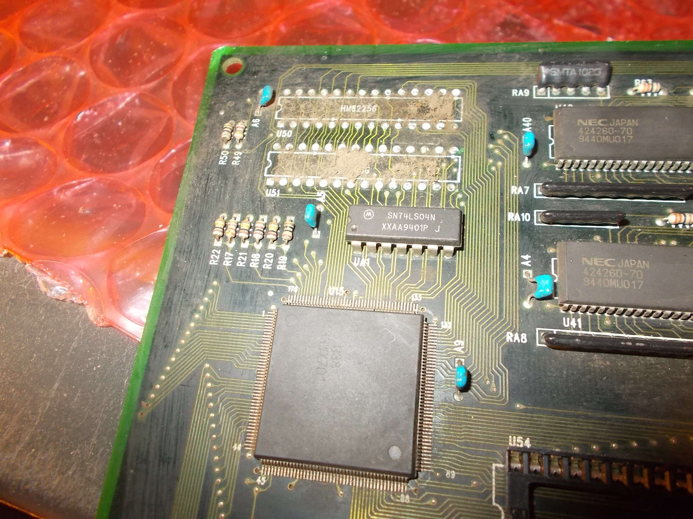
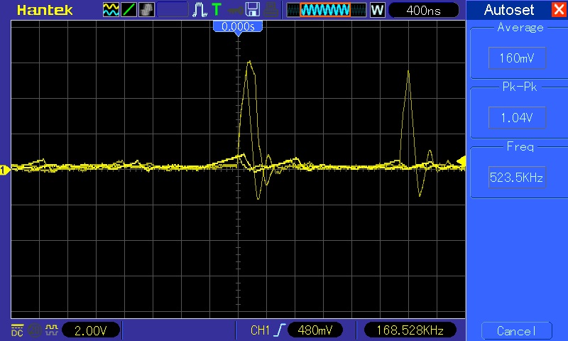
Each circuit consists in a QFP custom ASIC (maked ’38’) which addresses an 8Mbit MASK ROM (or a 2Mbit EPROM for the text layer) reading back data that then are written to two 8K x 8-bit static RAMs.After succesfully checked connection between ASIC, ROM and RAMs my suspicions fell on the 8k x 8-bit SRAMs, they were all manufactured by Sanyo so in my experience not a great guarantee of reliability.Probing the ones @U50 and U51 (which lie in the ‘layer 0’ circuit) revealed weak or stuck signals on many data lines:
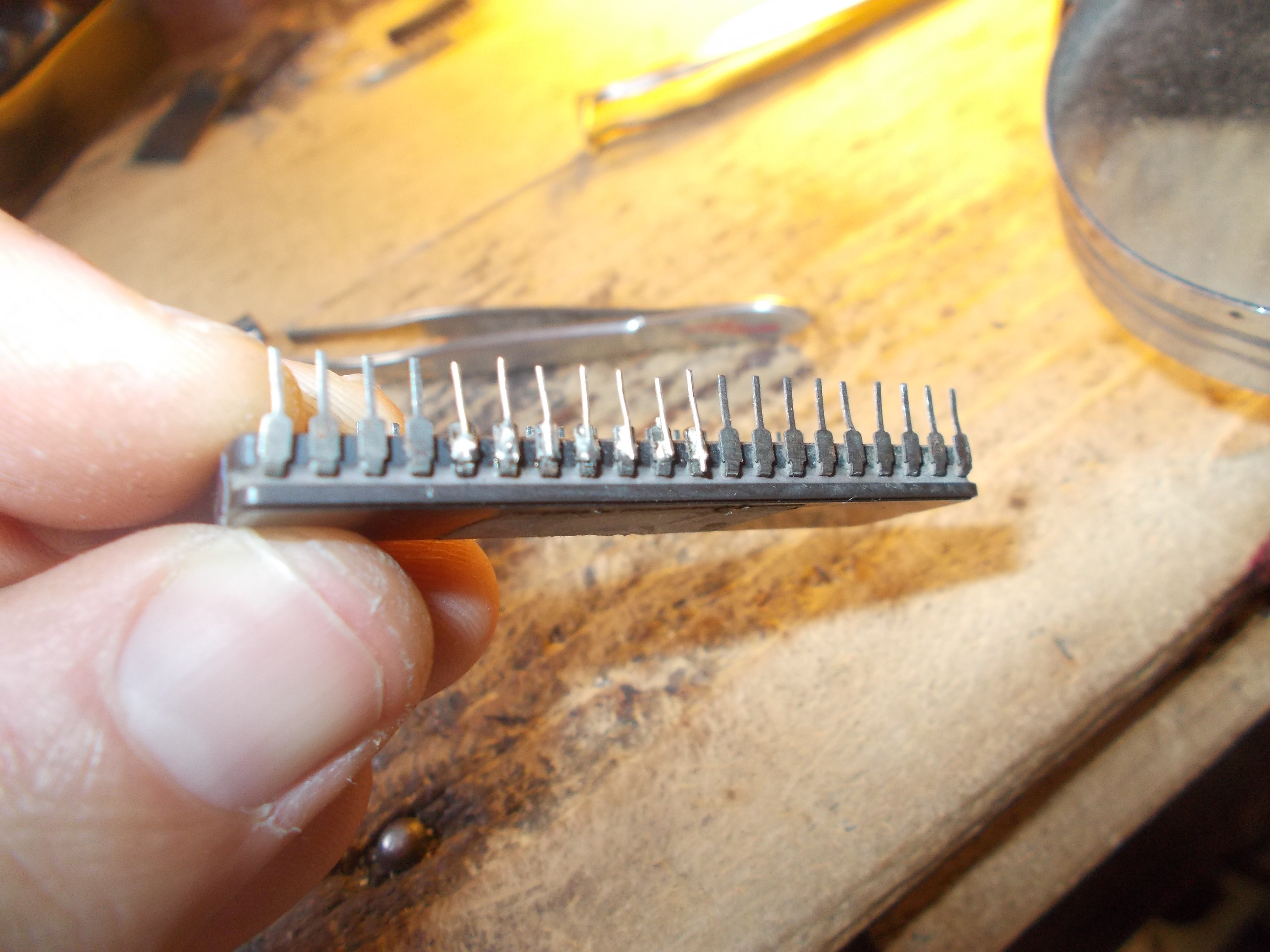
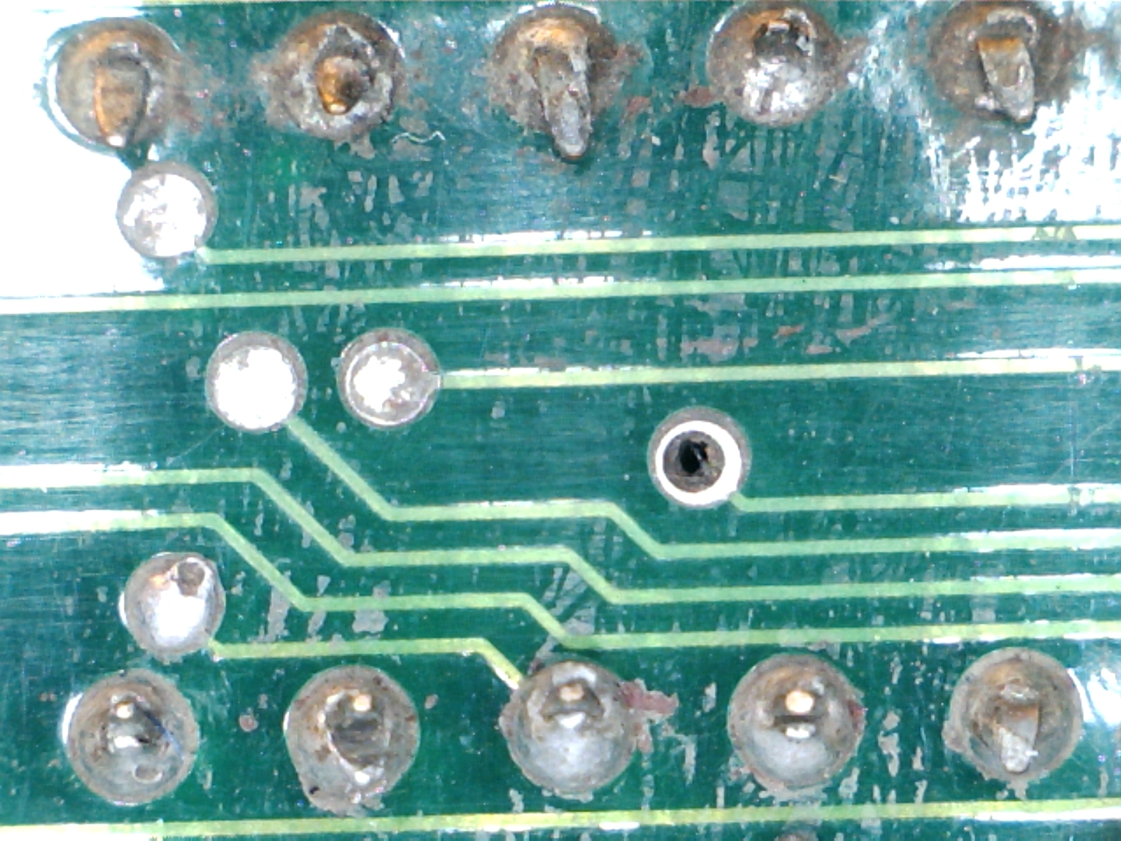
I removed both:
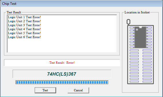
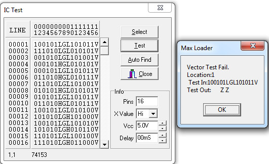
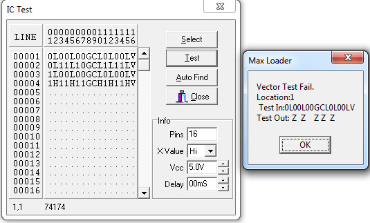
Actually only the one @U51 failed the out-of-circuit testing:
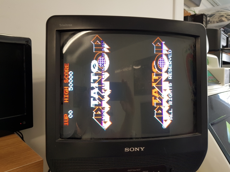
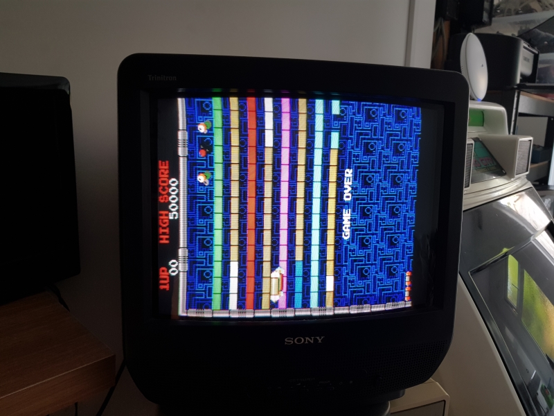
Now all graphics were visibile.Backgrounds and sprites were fine but text was corrupted throwing garbage over the screen :
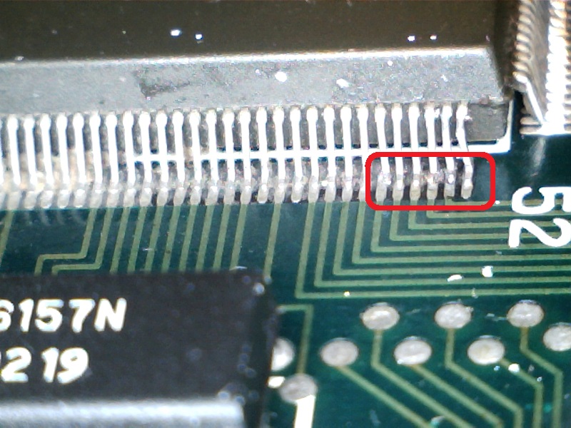
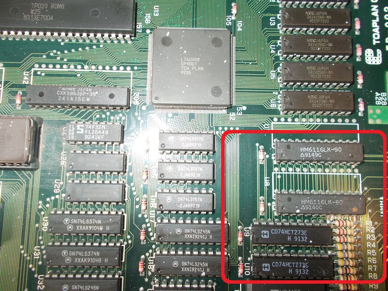
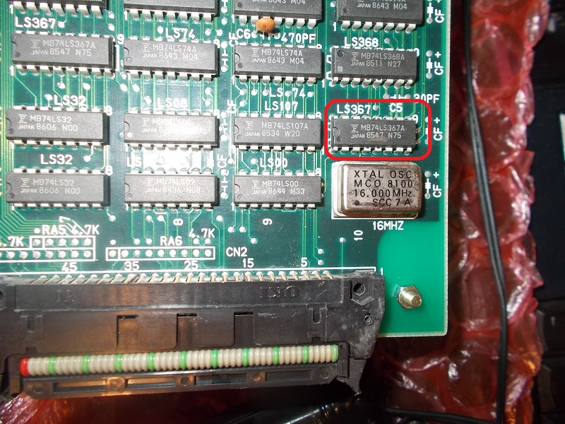
The ‘layer 2’ identified in MAME source as ‘ Text / Character Layer’ was obvioulsy the involved one.Checking the two Sanyo 8K x 8-bit SRAMs @U55 and U56 revealed again weak signals on data lines:
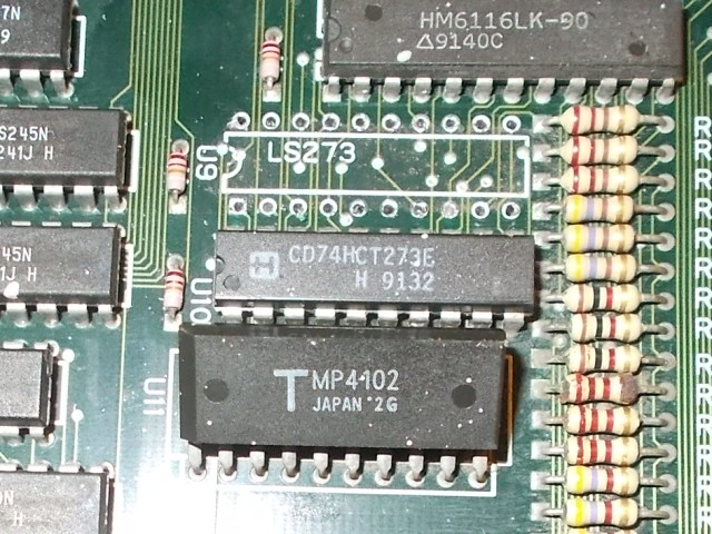
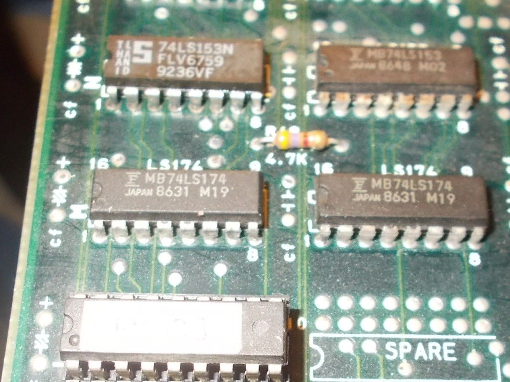
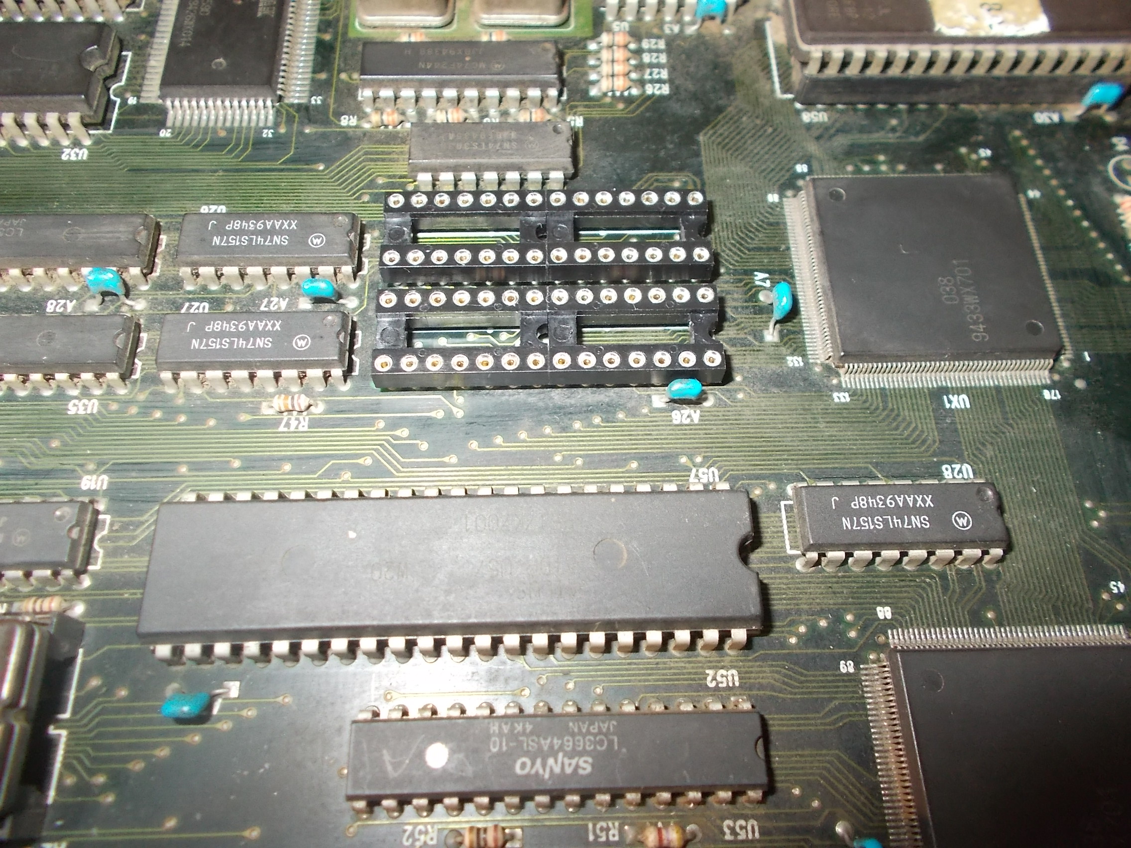
I removed them and installed machine sockets:
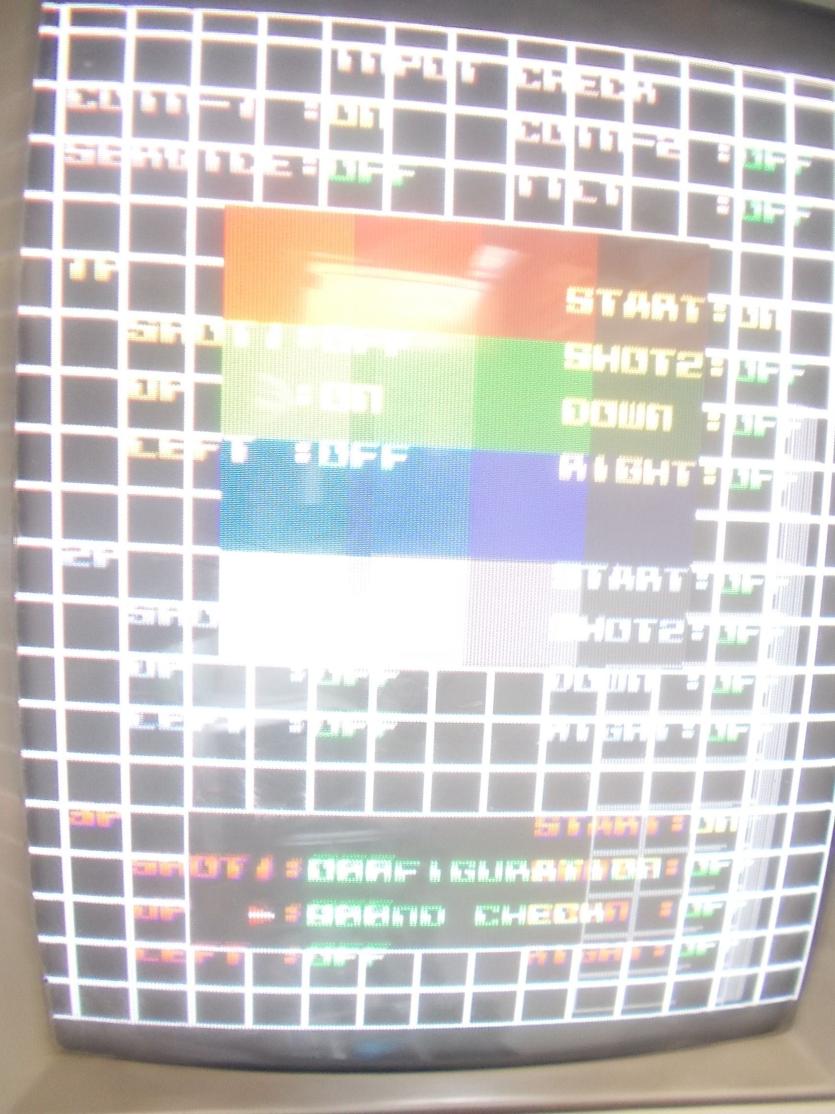
Actually both RAM chips successfully passed the out-of-circuit testing of my different programmers.Anyway, replacing them fixed completely the graphics:
But sound was horribly scratchy and corrupted as you can hear in the above video.Here it comes again to help my audio probe for checking the relevant circutit:
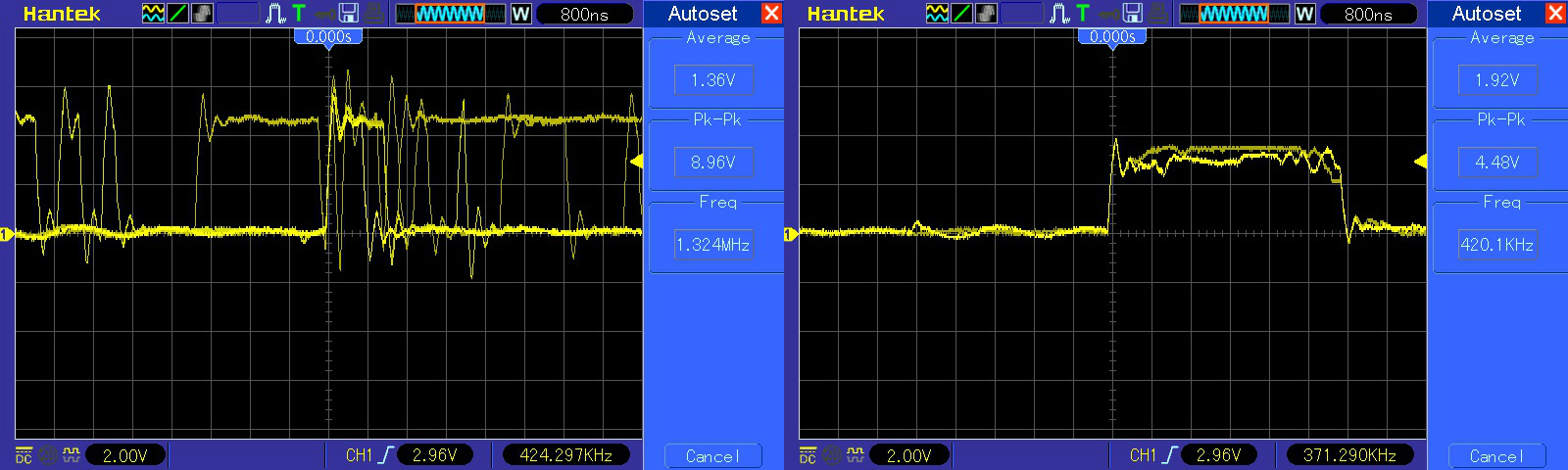
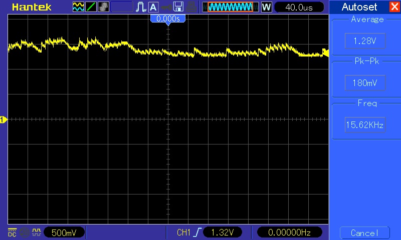
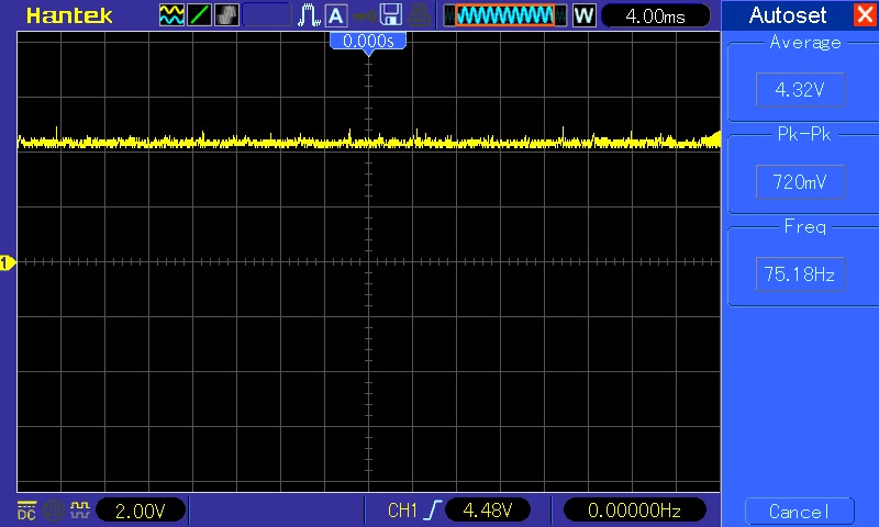
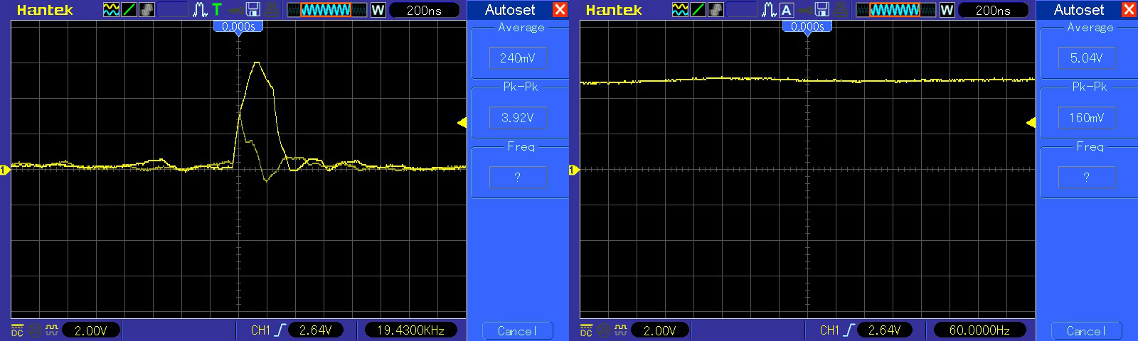
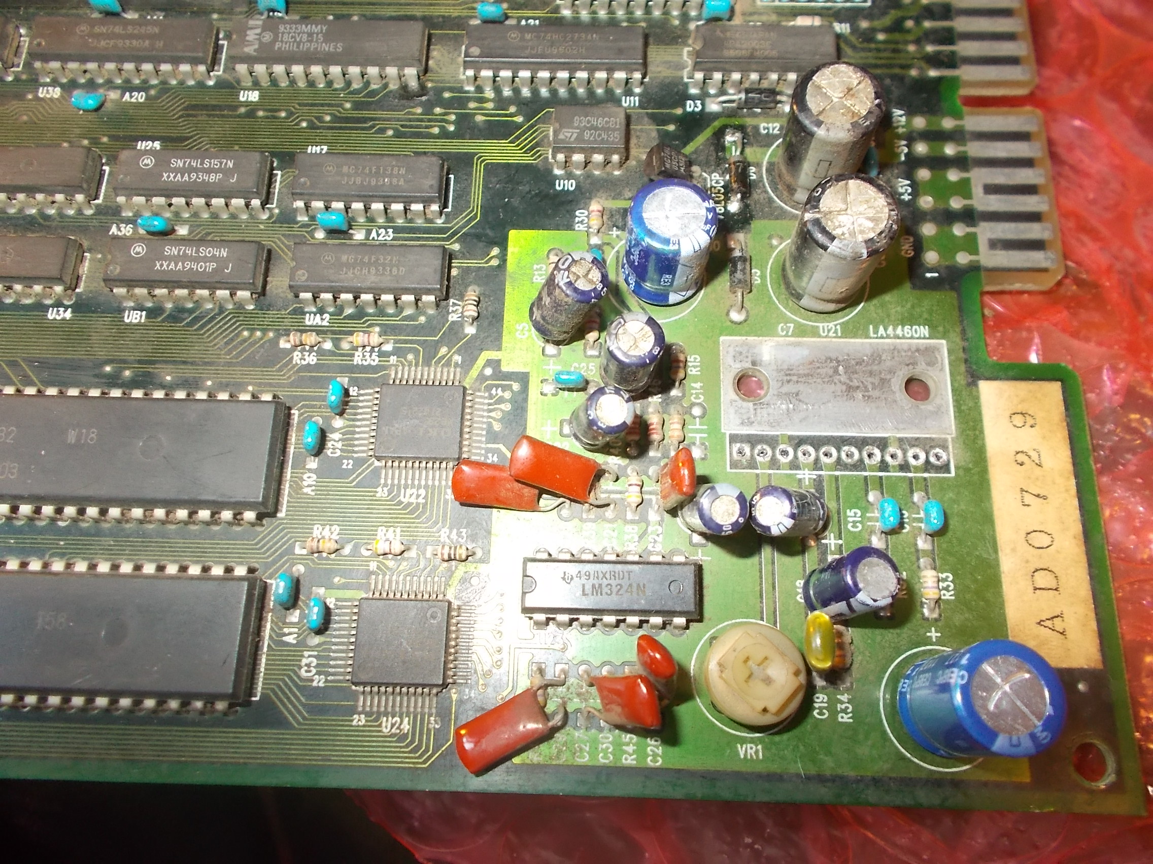
“Listening” to various points revealed the sound was clear on the analog output of the two OKI MSM6295 and still good on outputs of the LM324 OP-AMP and input of the LA4460 amplifer.It was fine too on one output (pin 7) of the LA4460 amplifier:
But corrupted on the other output (pin 9)
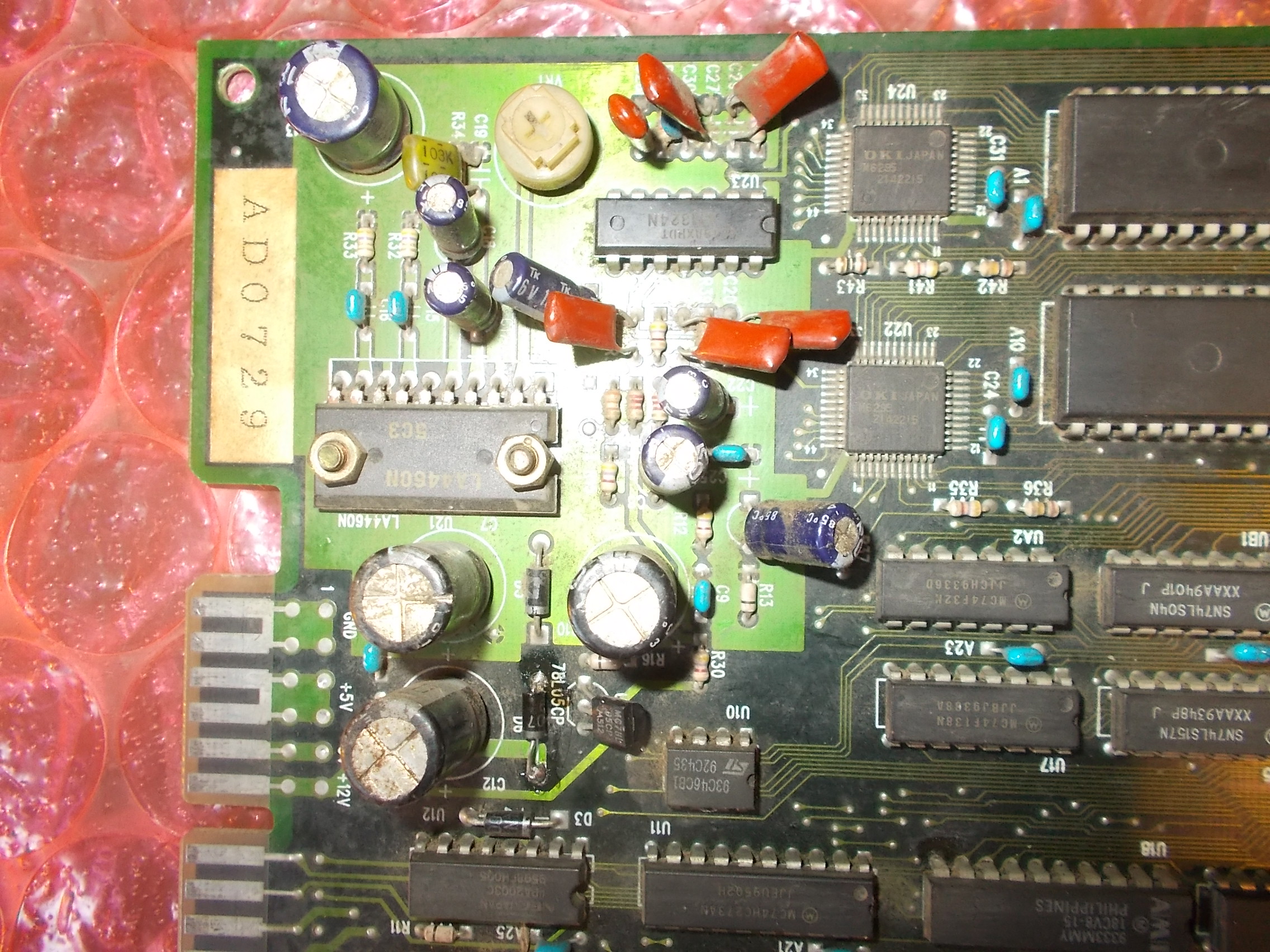
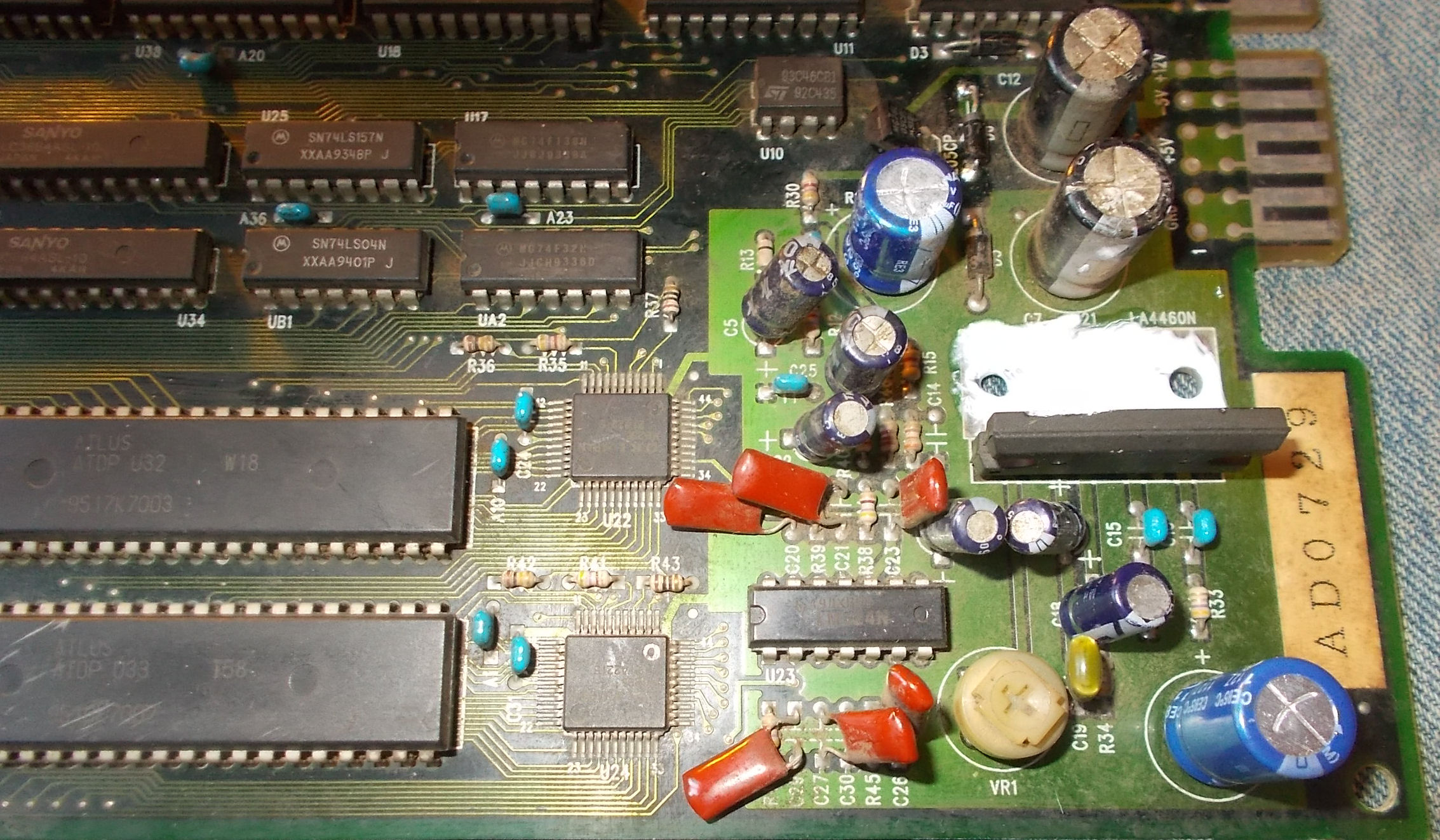
I ruled out all electrolytic capacitors checking them in-circuit with my ESR meter (bad ones can affect sound in this way) so I decided to remove the LA4460 amplifer:
Put back a good one and some thermal compound for a better heat dissipation:
This restored a crystal-clear sound.Mission DonPachi accomplished!