ReproductionsComments Off on Seibu ‘HB-45A’ reproduction
Jun082018
The ‘HB-45A’ is a custom IC used on some PCBs manufactured by Seibu like Raiden II/DX, Zero Team.It can be considered an evolution of the ‘HB-41’ that we already treated in a past article:
It shares the same 20 pin SIL package embedding most of the analog sound system.Its function is to mix and pre-amplify both music and sound FXs :
Here’s how it look “naked” of its external coating:
Design is almost identical to its predecessor with the presence of two OP-AMPs (a dual and a quad one) although they operate from a single supply (+12V) and not dual (+5V/-5V) like the ‘HB-41’.All other components are ceramic/tantalum capacitors and resistors (surface mounted and printed film ones) which are part of the application circuit of the two OP-AMPs
It took some time to draw schematics not without some difficulty due the presence of some hidden printed film resistors located under the quad OP-AMP:
Schematics were then routed to a PCB which looked pretty good on a 3D preview :
The real thing assembled in all its parts :
For a while I was not able to test this reproduction due the lack of a working PCB (the “decapped” original part was taken from a dead board) until the user ‘opt2not’ from Arcade Projects and KLOV forums kindly volunteered.The test platform was his working Raiden DX PCB.He first removed the original ‘HB-45A’ in a very clean way (he used an Hakko FR-300 desoldering gun)
Installed some female 2.54mm round machined headers:
Lastly the reproduction fitted onto the board:
Then he made recordings of audio of both original custom and reproduction redirecting it to a PC from a HAS supergun using a SPDIF breakout from the SCART connection.
Here ‘s capture using the original HB-45A:
Here’s the one using my reproduction:
Comparing the music and FXs at the beginning and end of the recordings sound identical.No differences in quality can be noticed (the slight background noise is normal when there is silence).
For this successful reproduction project I would like to thank again ‘opt2not’ for his precious testing and all material (pictures and audio captures) he provided me.I recommend you to check out his blog :
Was asked by a friend to repair his Sunset Riders.
When starting up the PCB, it was stuck in something resembling a watchdog fault.
But I’ve been working on Sunset Riders before and this didn’t seem like an ordinary watchdog. I felt that it went a little bit longer in the startup sequence before crashing.
The board was a bit dirty but I started with the usual:
Checking CPU signals like clock, reset and halt
Verifying the program ROMs
Checking the program RAM for odd signals
All looked ok, but then I found this at the 051550 reset signal generator.
Pin 1 on the 051550 looked like a cold solder joint.
Pin 1 is the clock signal input pin on this IC and without that input, I can understand that the game doesn’t boot up properly. Gave that pin a dab of solder
Although I grew up with a Commodore 64, I have a soft spot for Atari 8 bit machines. My mission in life is to save them all from going into landfill.
I spotted this grimy Atari 800XL on Gumtree very recently as untested, it came with an Atariwriter Word Processor Cartridge. I met the friendly chap selling the item and we did the exchange for the computer at Town Hall steps, which is a popular meeting place in Sydney.
Taking the machine apart, I was happy to see that the machine was fully socketed and that the PCB was in excellent condition despite it needing a good clean. Actually, I was expecting a fully socketed machine because it was made in Hong Kong just like my 600xl was. Another pleasant surprise was the brand of DRAMs used ( OKI ) instead of the mT variety, which have a bad reputation for reliability and were used extensively in the Atari 8 bit and C64 line.
I had a close friend of mine over after work and we went through the troubleshooting together. Unfortunately, not much happens after power it up. A black screen most of the time and sometimes an intermittent picture, obviously this is a sync issue.
Sometimes I manage to get a screen that looks like this. This is a good sign. At least I know the CPU, ROMs and DRAMs are working to some extent to produce this screen.
Luckily I have a fully socketed 65XE to swap parts to and from. I also tried a known semi good GTIA which was bad on one output only but produced a nice clean picture in a working machine. The GTIA is responsible for generating the luminance, color and csync signals to produce an image to the screen.
Replacing it doesn’t change a single thing so I consult the schematics, the signals go directly to a hex non inverting buffer ( 4050 ) so I switch my logic probe to the CMOS setting and start probing the chip. Output 6 ( lum0 ) is good, lum1, 2 and 3 were all bad and all outputs were floating. I wanted to check the CYSNC line ( composite sync ) and that was also floating ( no signal at all ).
I short the input and output pins of the 4050 ( pins 14 & 15 ) with my logic probe briefly which restores the picture to the screen.
Replacing the chip completes the job!
Now onto the next challenge, cleaning the motherboard and case!
ROM_REGION( 0x040000, “layer2”, 0 ) /* Text / Character Layer */
ROM_LOAD( “text.u58”, 0x000000, 0x040000, CRC(5dba06e7) SHA1(f9dab7f6c732a683fddb4cae090a875b3962332b) )
I translated this info on hardware and figured out the relevant circuit of each layer:
Each circuit consists in a QFP custom ASIC (maked ’38’) which addresses an 8Mbit MASK ROM (or a 2Mbit EPROM for the text layer) reading back data that then are written to two 8K x 8-bit static RAMs.After succesfully checked connection between ASIC, ROM and RAMs my suspicions fell on the 8k x 8-bit SRAMs, they were all manufactured by Sanyo so in my experience not a great guarantee of reliability.Probing the ones @U50 and U51 (which lie in the ‘layer 0’ circuit) revealed weak or stuck signals on many data lines:
I removed both:
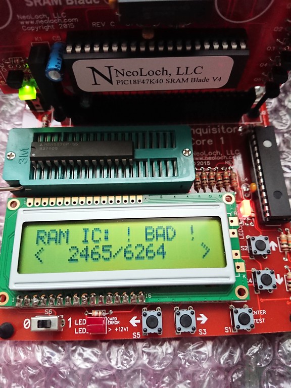
Actually only the one @U51 failed the out-of-circuit testing:
Now all graphics were visibile.Backgrounds and sprites were fine but text was corrupted throwing garbage over the screen :
The ‘layer 2’ identified in MAME source as ‘ Text / Character Layer’ was obvioulsy the involved one.Checking the two Sanyo 8K x 8-bit SRAMs @U55 and U56 revealed again weak signals on data lines:
I removed them and installed machine sockets:
Actually both RAM chips successfully passed the out-of-circuit testing of my different programmers.Anyway, replacing them fixed completely the graphics:
But sound was horribly scratchy and corrupted as you can hear in the above video.Here it comes again to help my audio probe for checking the relevant circutit:
“Listening” to various points revealed the sound was clear on the analog output of the two OKI MSM6295 and still good on outputs of the LM324 OP-AMP and input of the LA4460 amplifer.It was fine too on one output (pin 7) of the LA4460 amplifier:
But corrupted on the other output (pin 9)
I ruled out all electrolytic capacitors checking them in-circuit with my ESR meter (bad ones can affect sound in this way) so I decided to remove the LA4460 amplifer:
Put back a good one and some thermal compound for a better heat dissipation:
This restored a crystal-clear sound.Mission DonPachi accomplished!