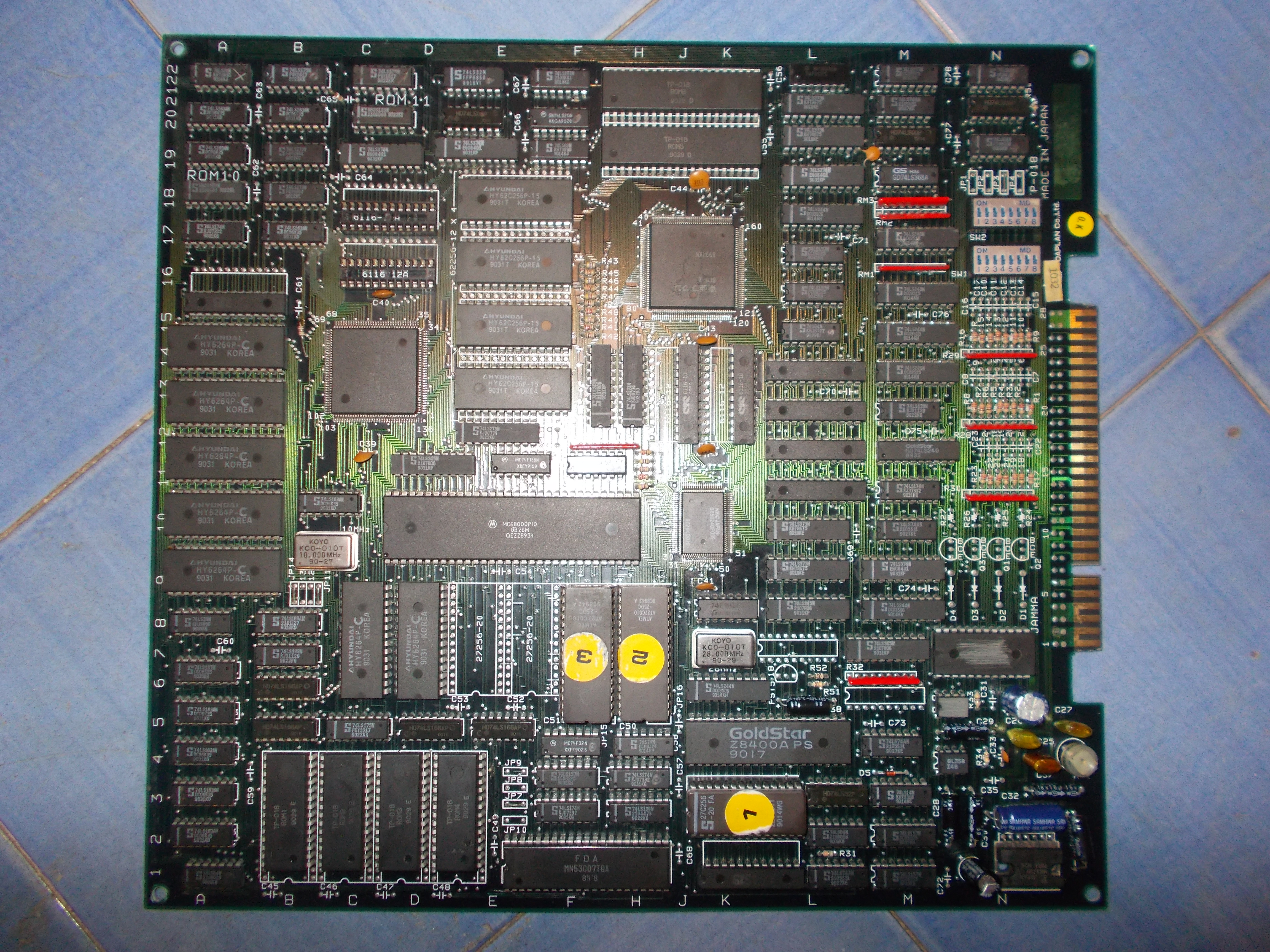
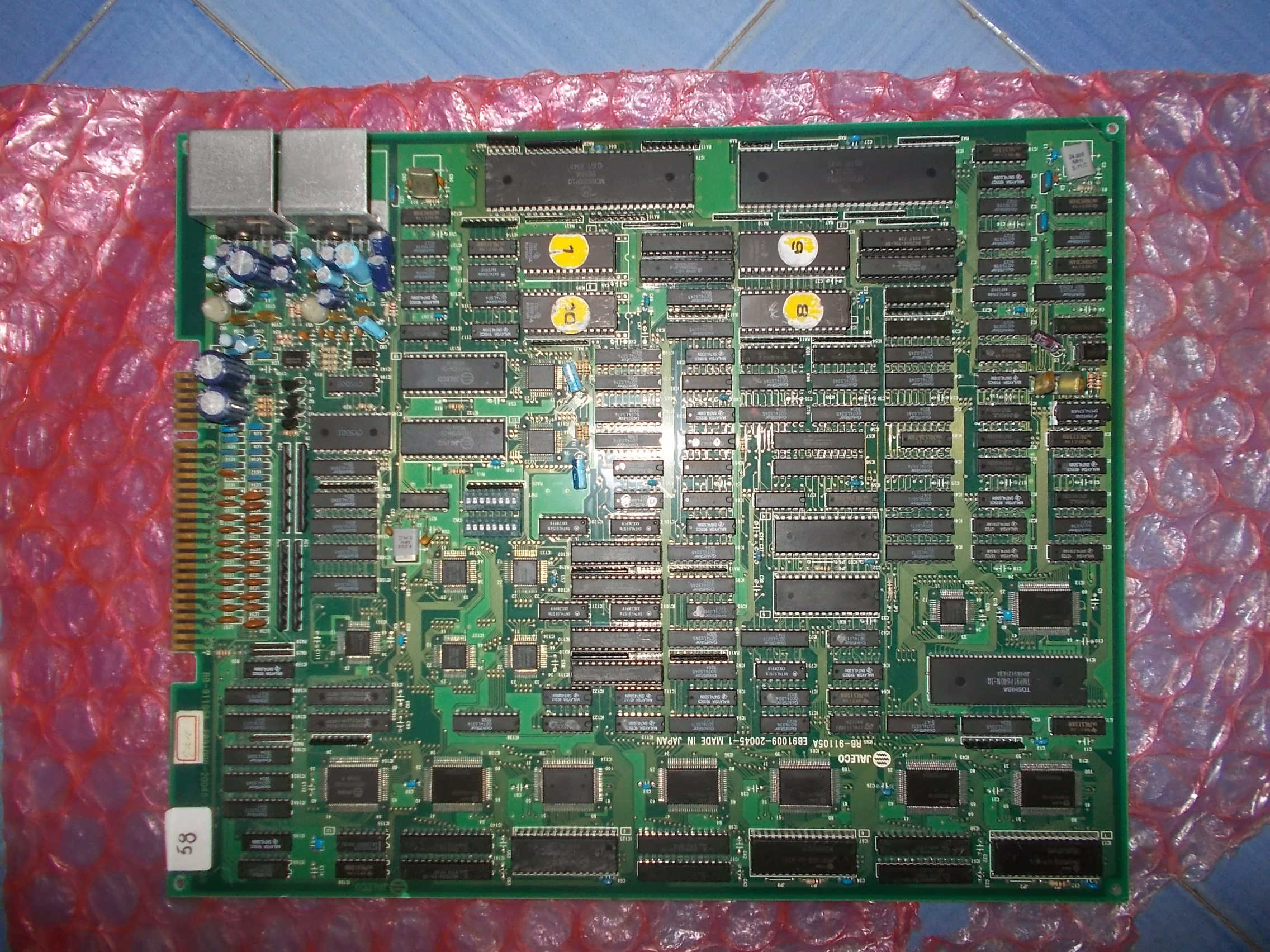
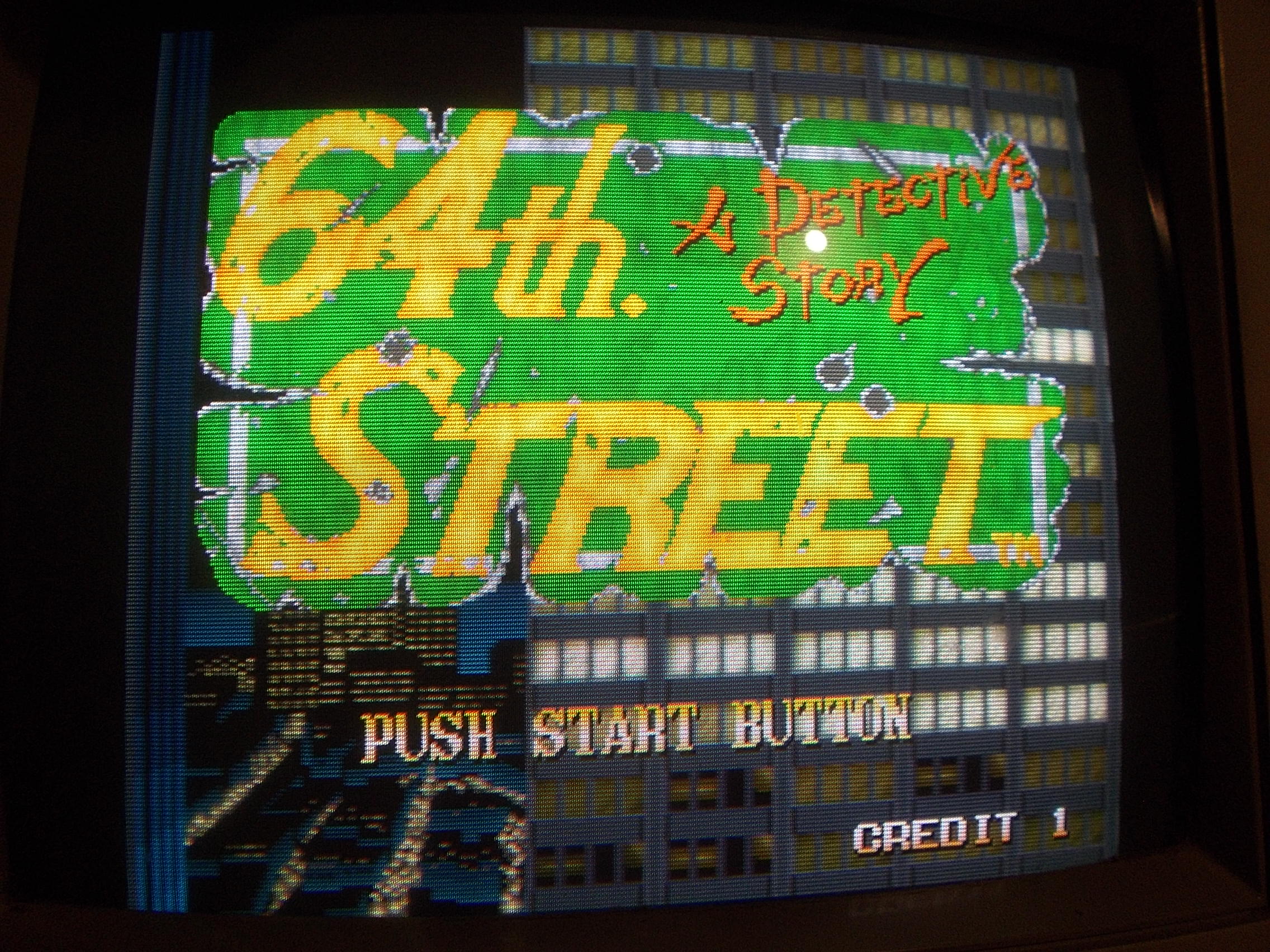
Got from Portugal this mint 64th Street – A Detective Story PCB, a beat ’em up released by Jaleco in 1991 :
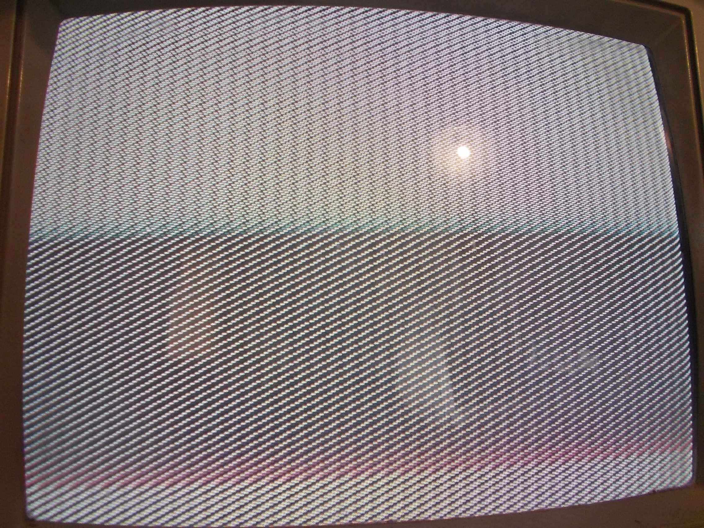
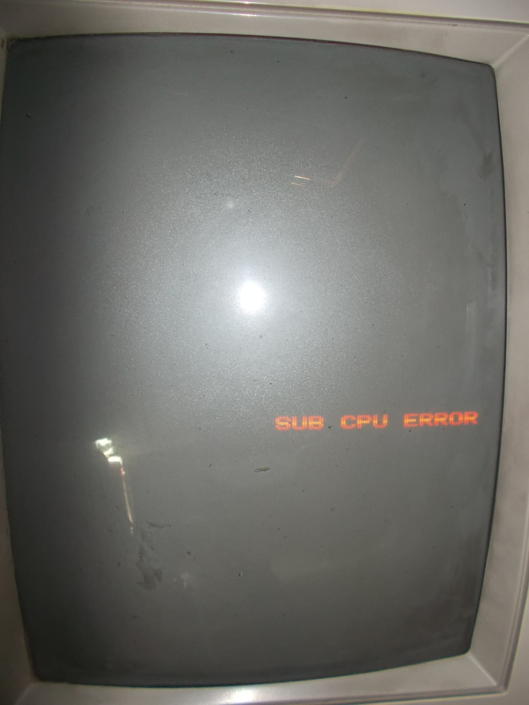
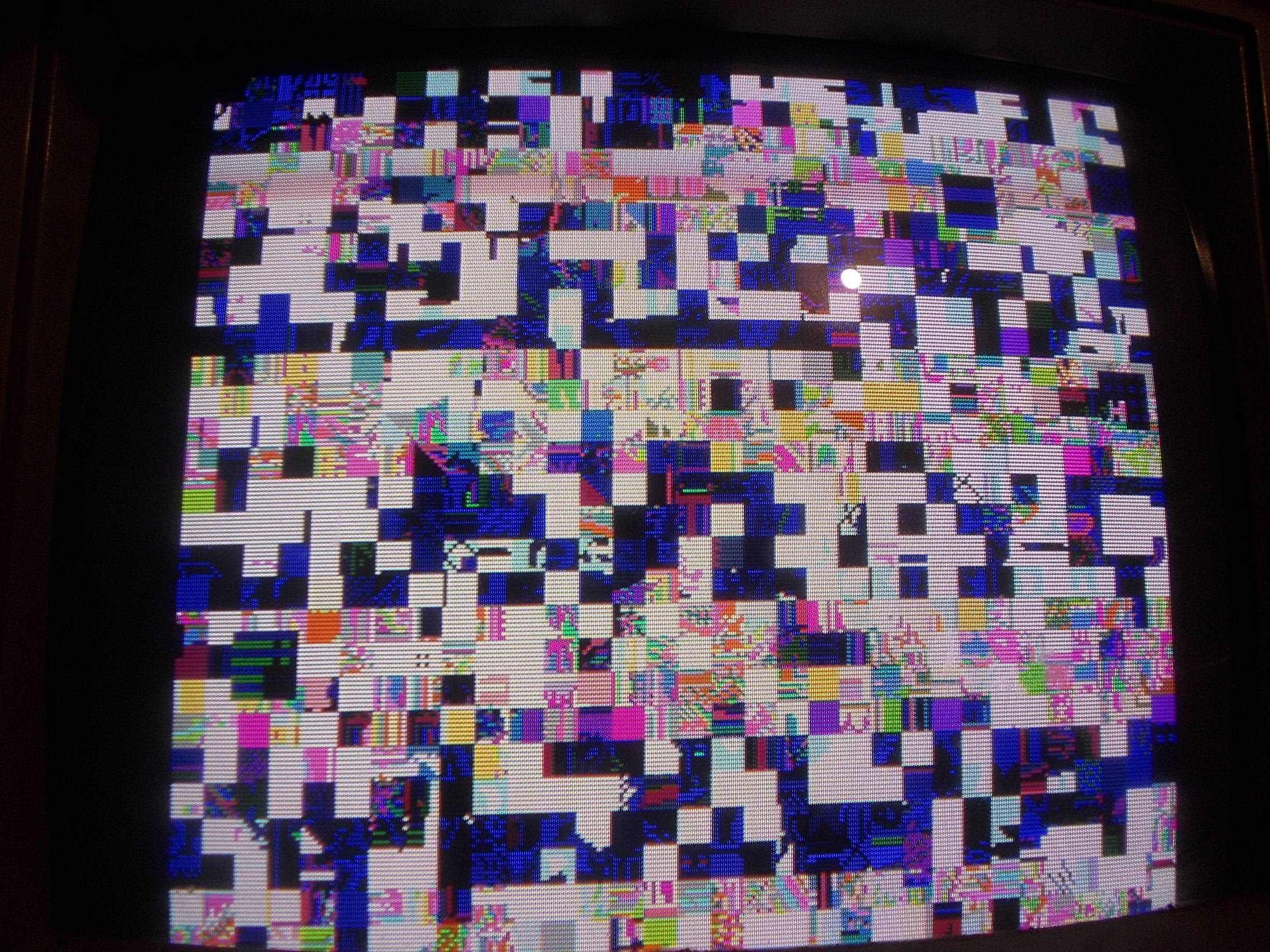
The board simply booted to a static garbage screen:
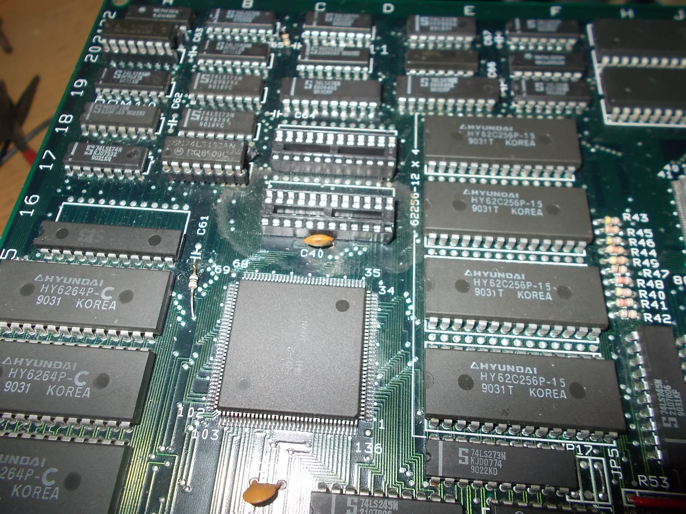
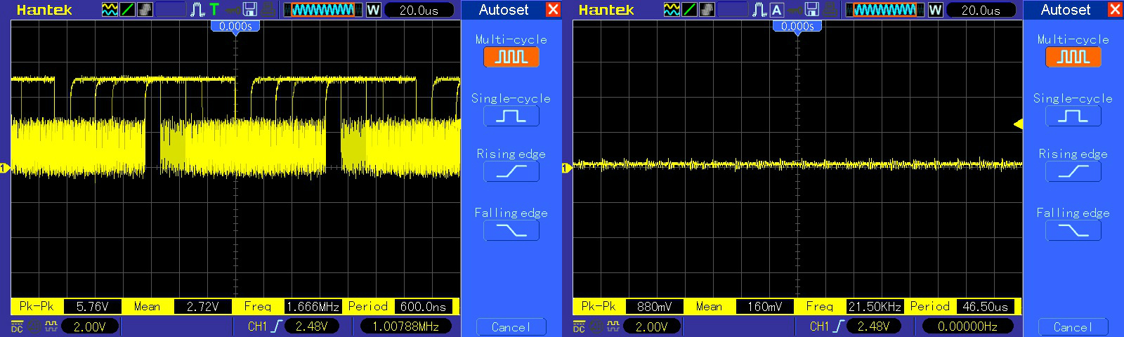
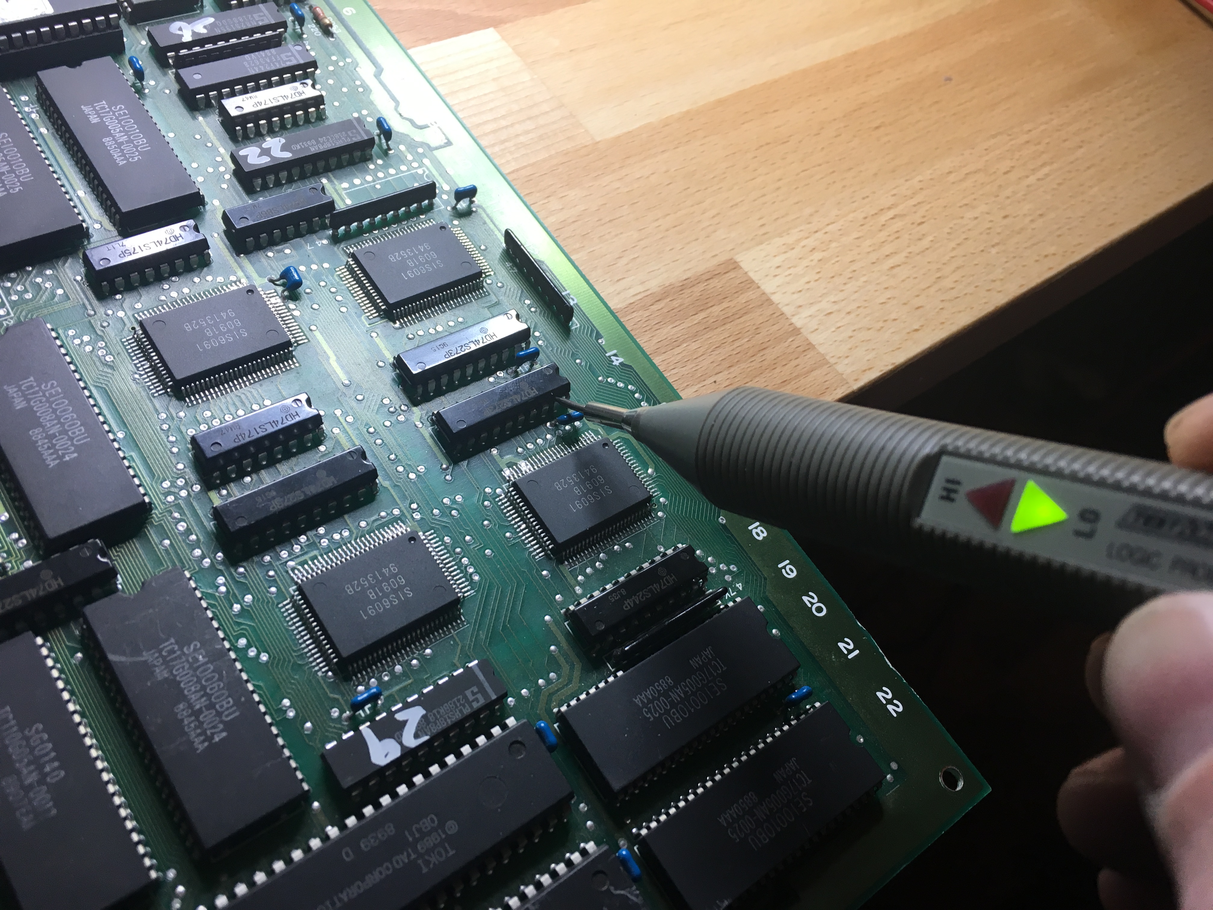
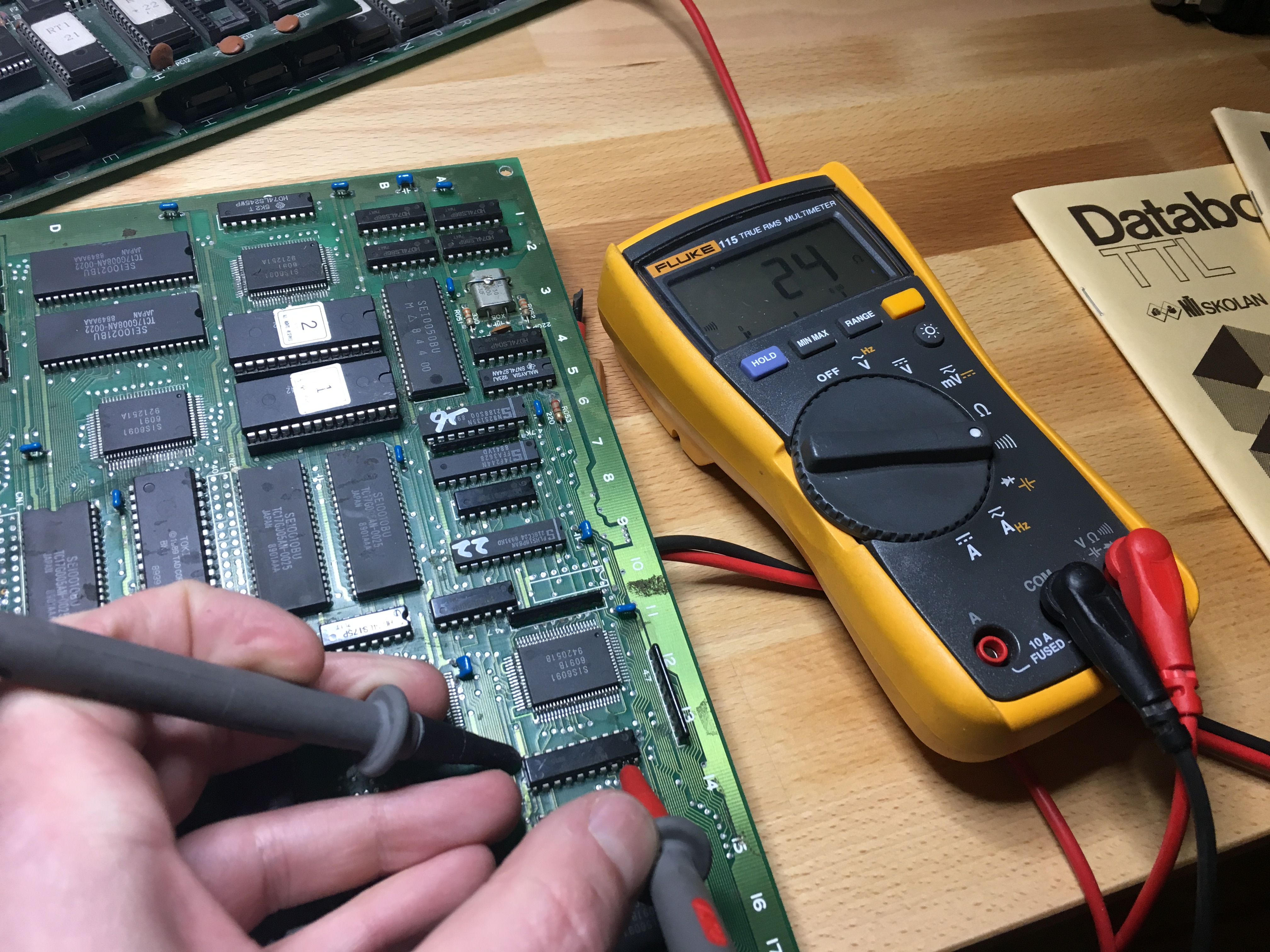
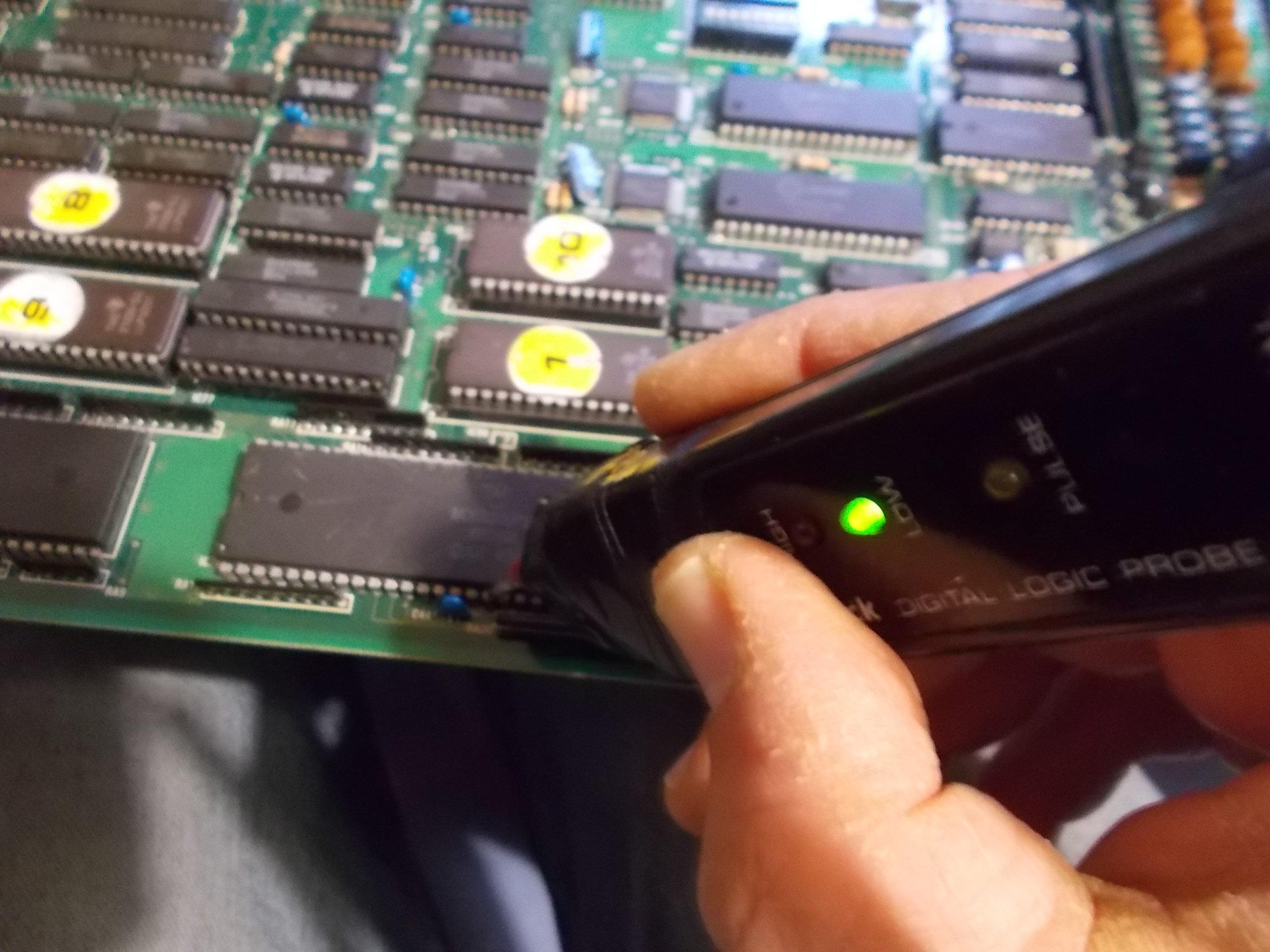
At a deeper analysis both 68000 CPUs were not resetting properly on power up :
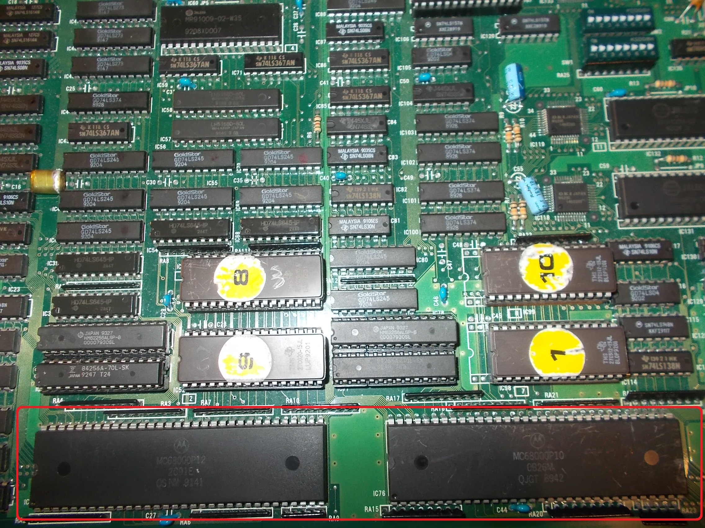
On the main one there was no transition from LOW to HIGH state, /RESET line went staight HIGH :

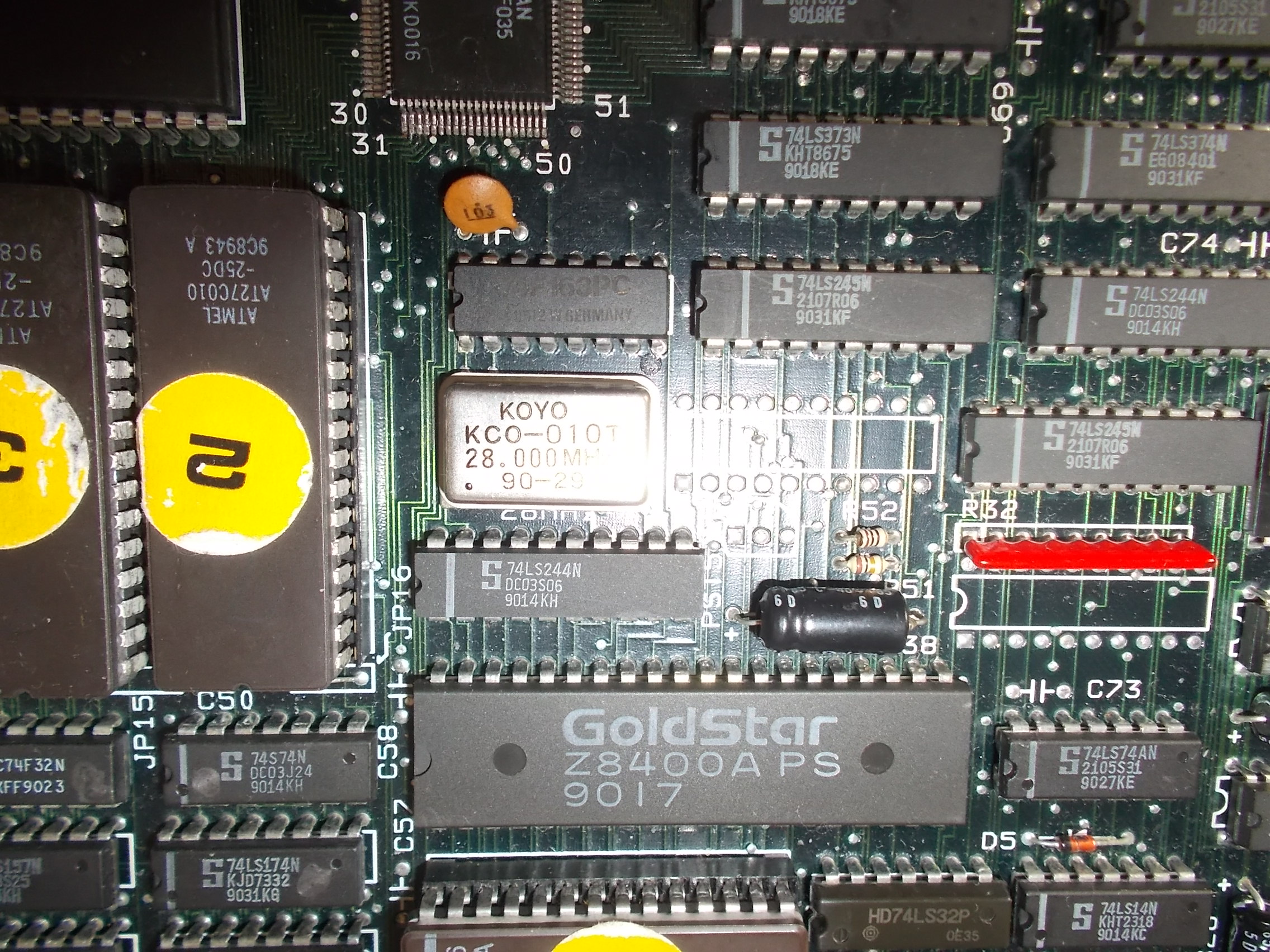
On the sound CPU both /HALT and /RESET lines were stuck LOW:
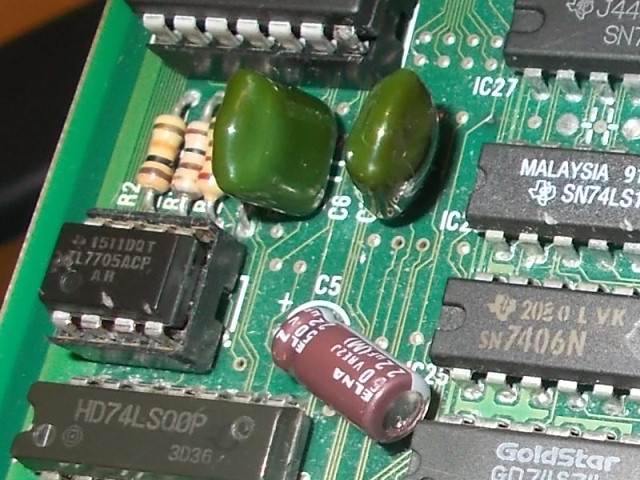
I traced back the lines to a typical power-on reset circuit based on the TL7705 voltage monitor IC which I replaced with no luck:
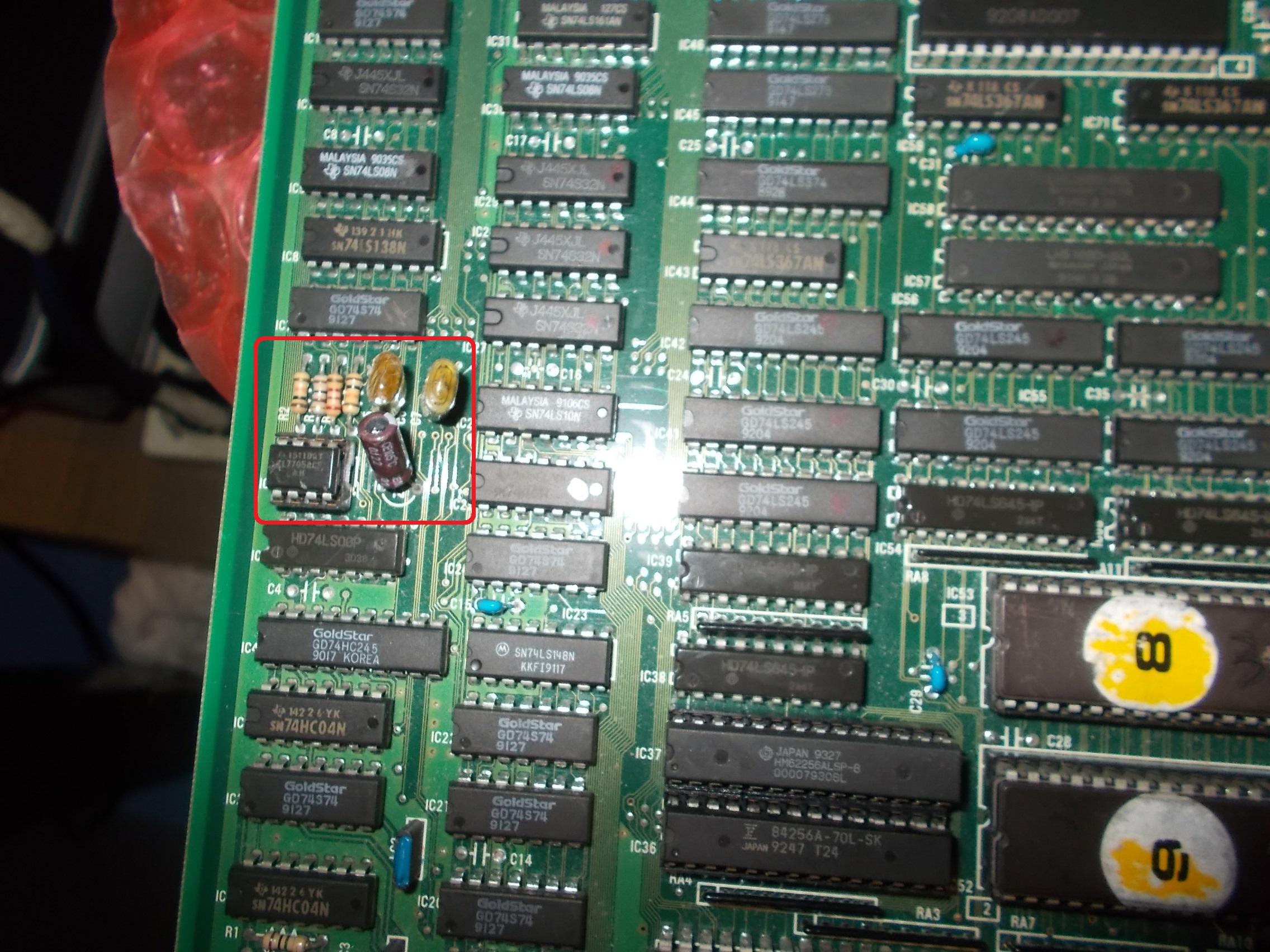
The circuit is made of few other components, specifically there are two 0.1uF mylar capacitors connected to pin 1 (REF) and pin 7 (SENSE)
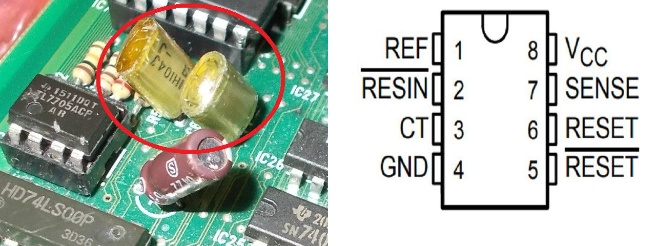
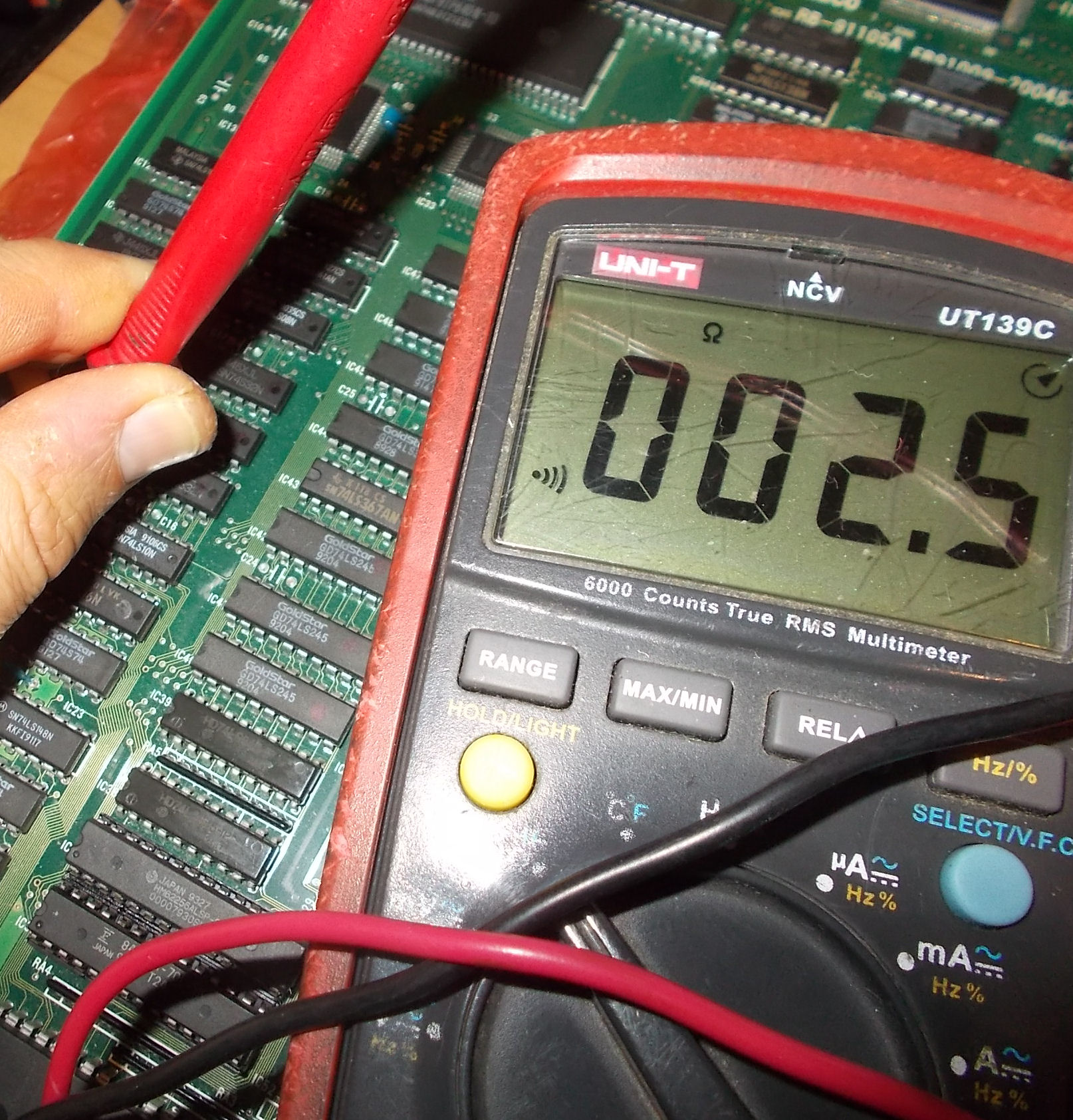
I got few Ohms when I measured resistance across their terminals (after detached one leg from circuit), they were almost shorted :
I replaced them :
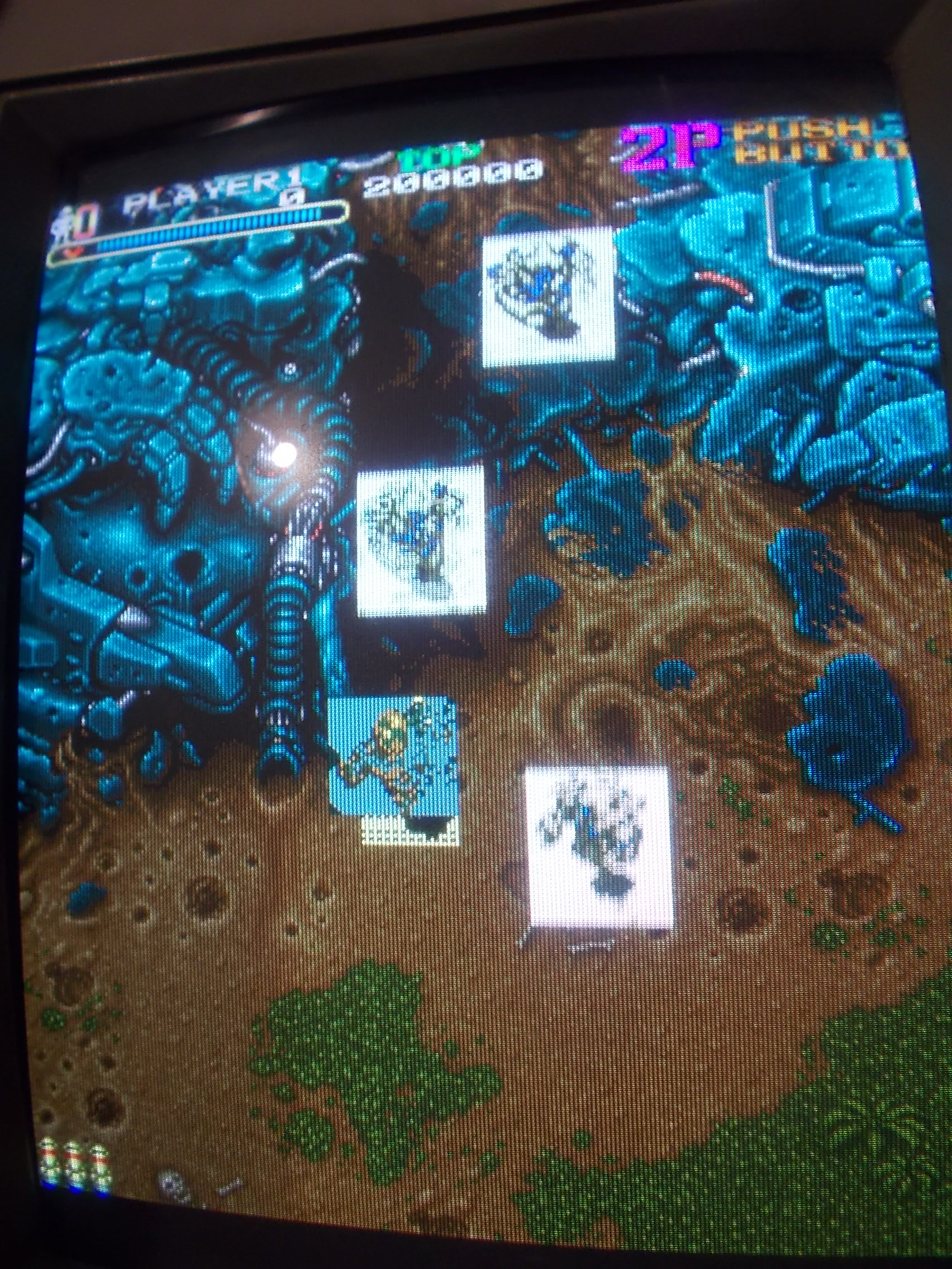
Board successfully booted into game with no further issue :
Repair accomplished.