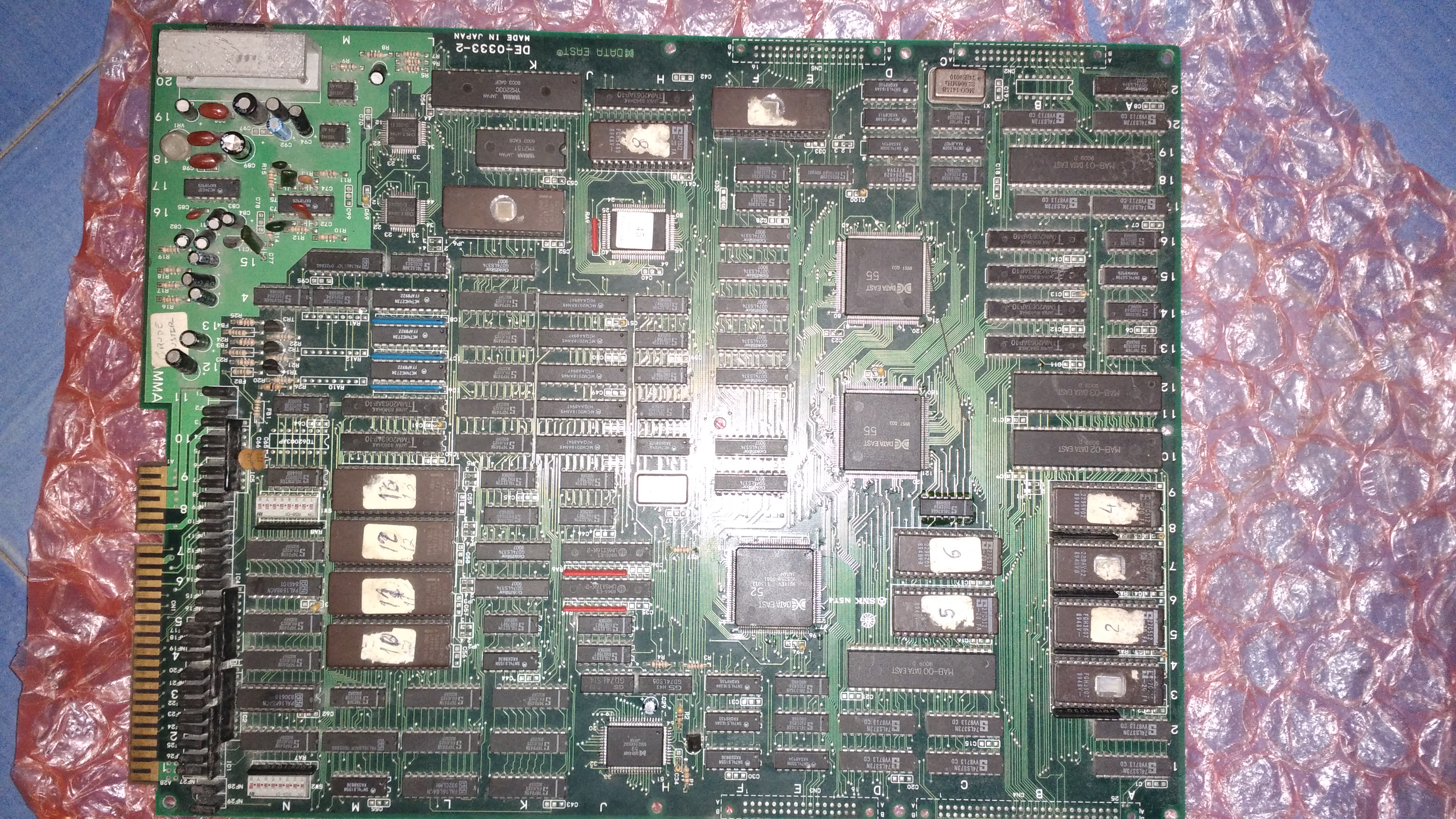
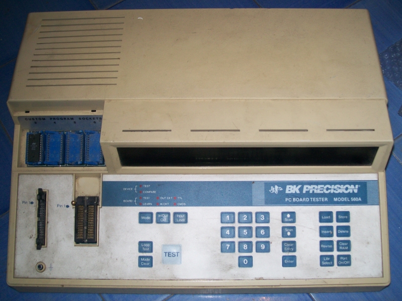
Some time last year I attended an arcade meet of UKVAC user ‘Bonehead’. It was here that I met up with Virtvic who brought along a couple of boards that needed repair. Among them was this Arkanoid 2 which has had a few attempts of repair by a few different people. Because of this it also came with a list of suspected bad components.
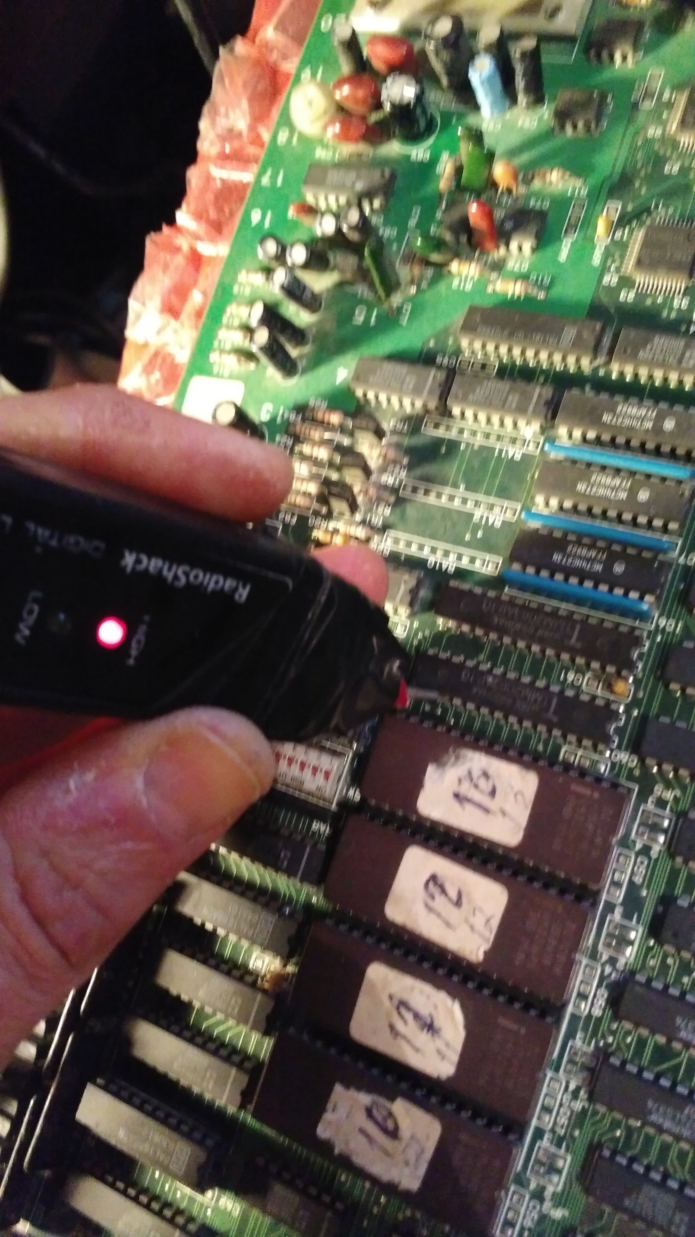
Among the list of suspected dead parts was the Z80 Sub CPU. I tested this and it was indeed dead.
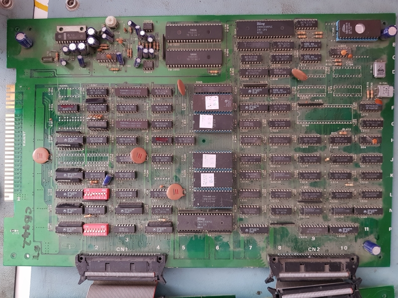
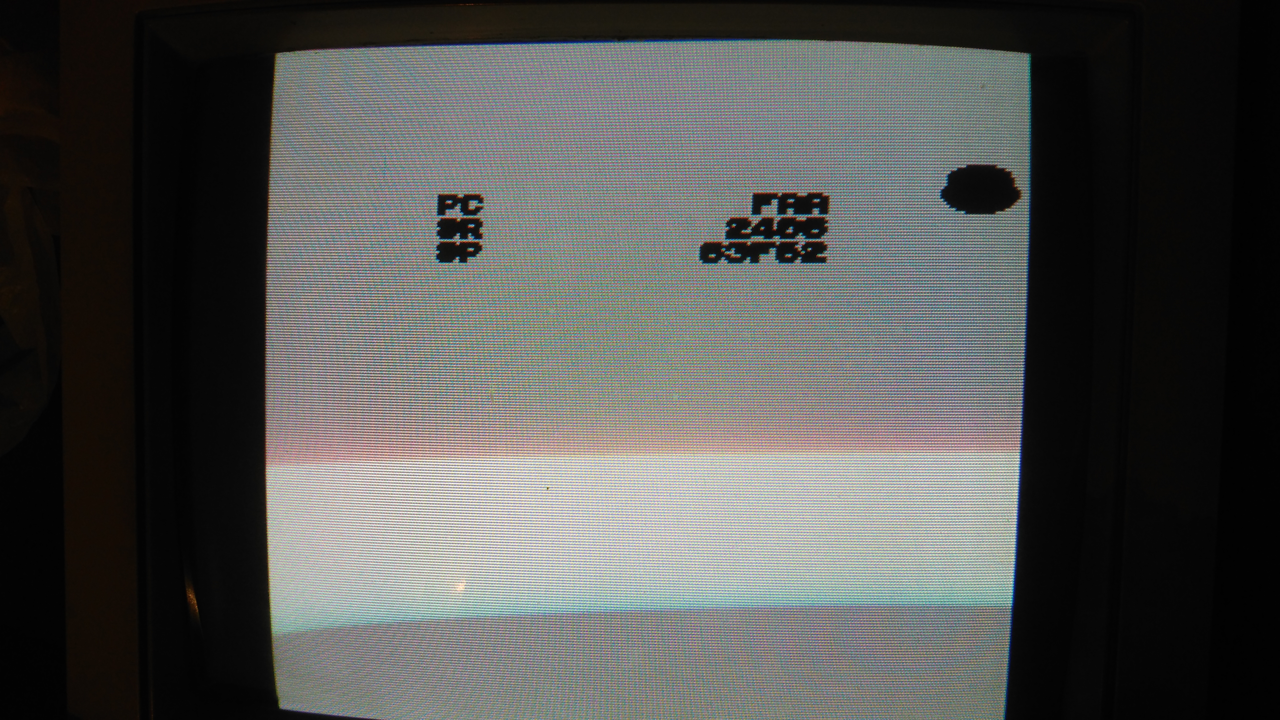
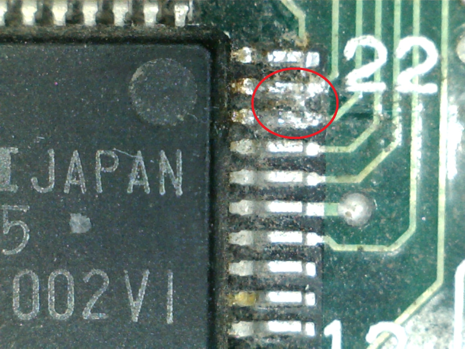
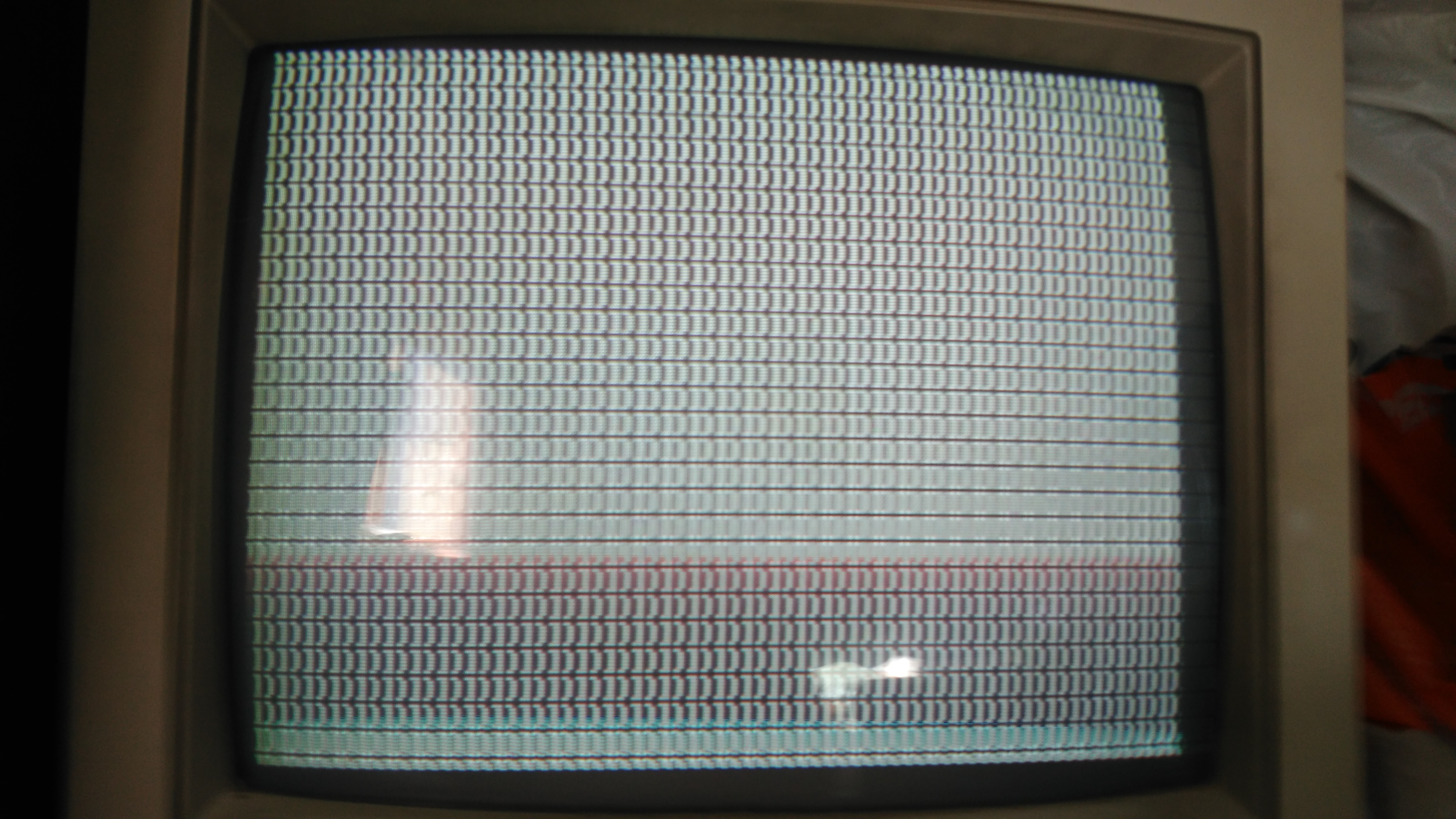
After a quick visual inspection I fired it up and got a “SECURITY ERROR” on screen.
The security error is generated from the sub CPU and is all to do with the MCU which is part of the sub CPU section.
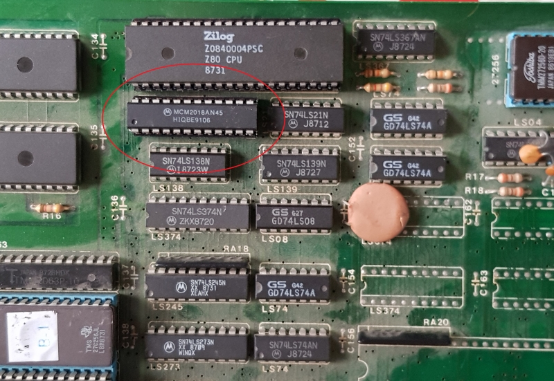
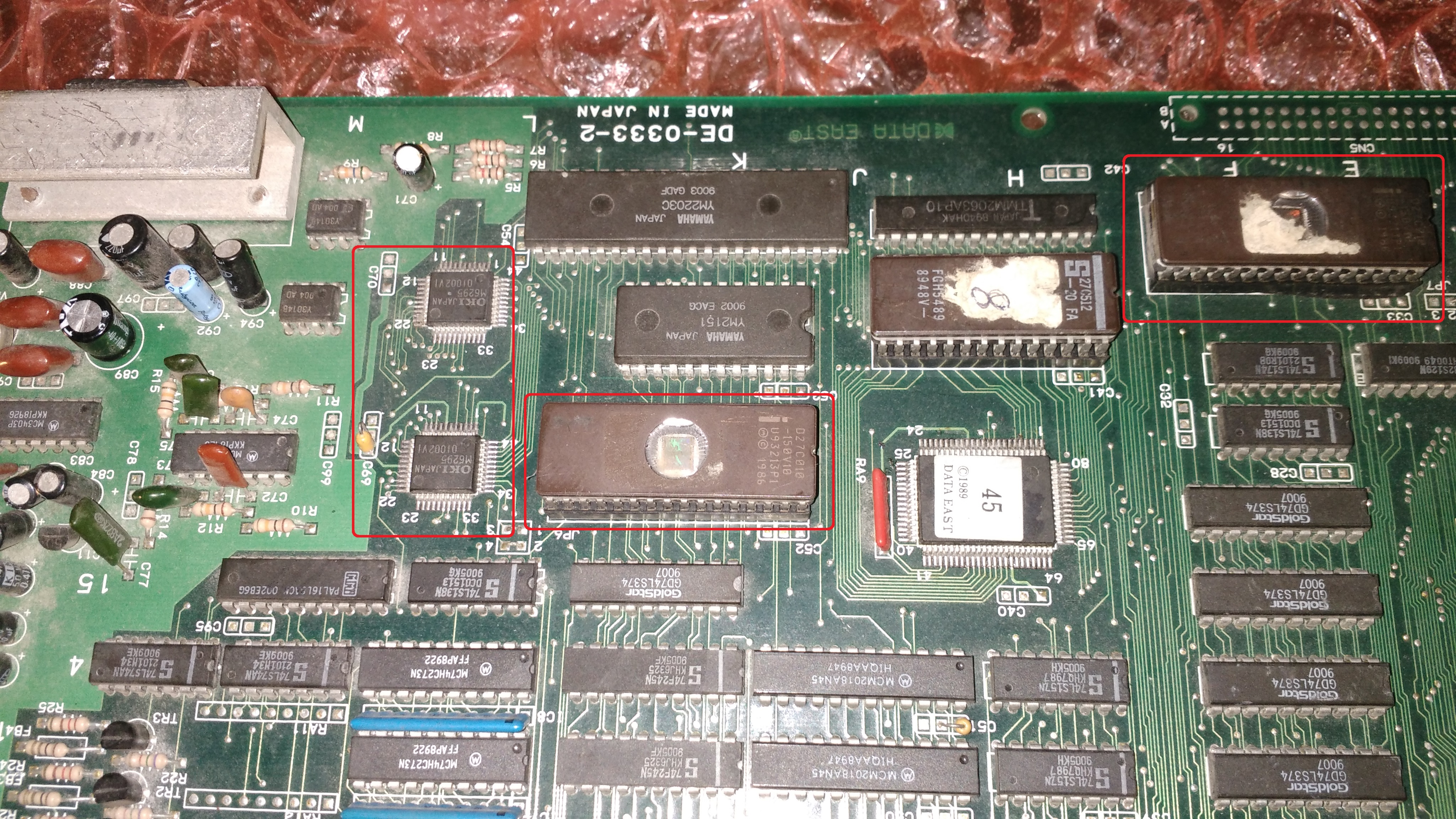
I pulled the ROM and it failed in the programmer with an “OVER CURRENT” error. At this point I was getting suspicious and set about checking other chips on the same busses. Everything on the same bus as the sub cpu was dead. The list includes:
Z80
PAL
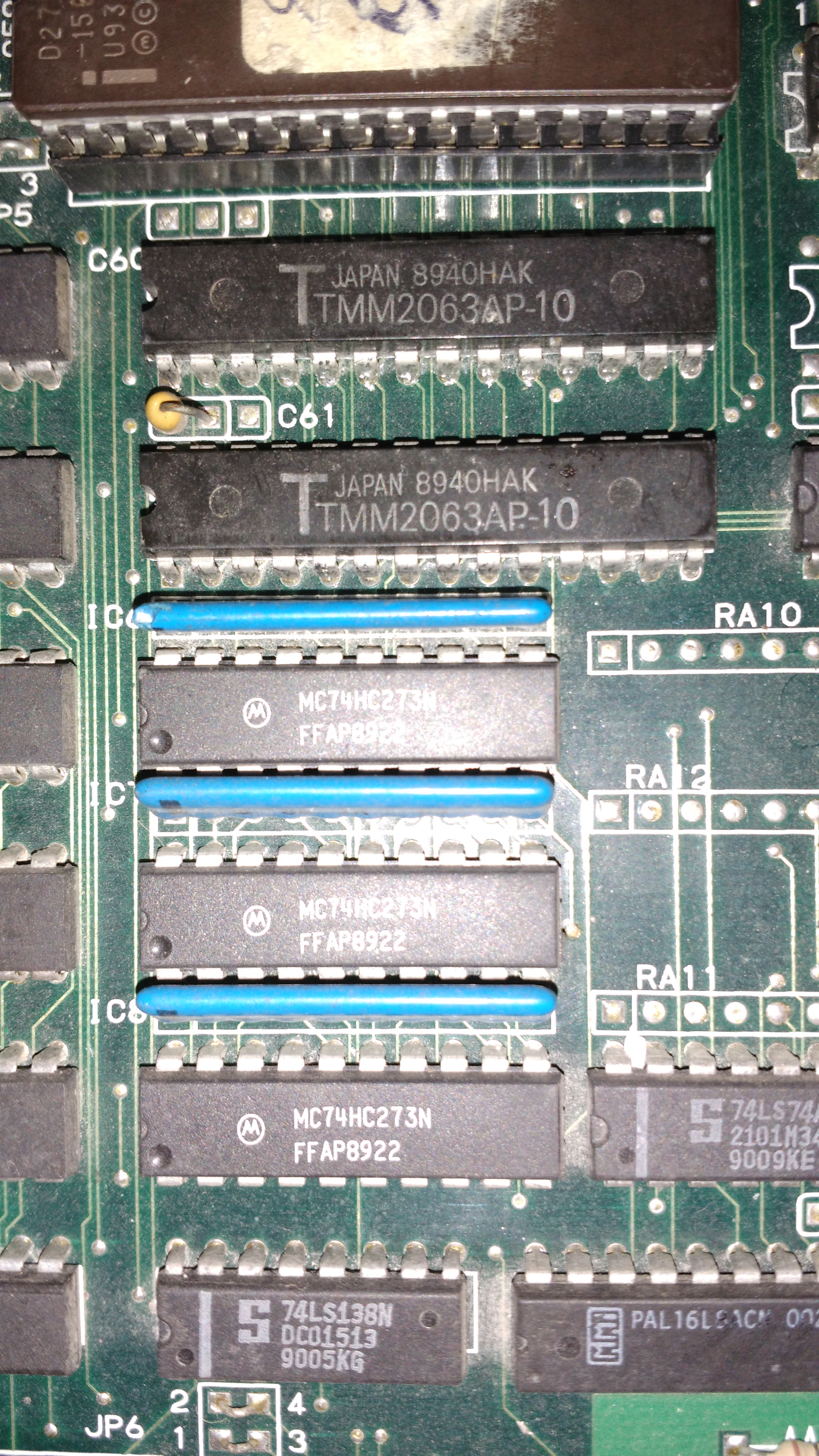
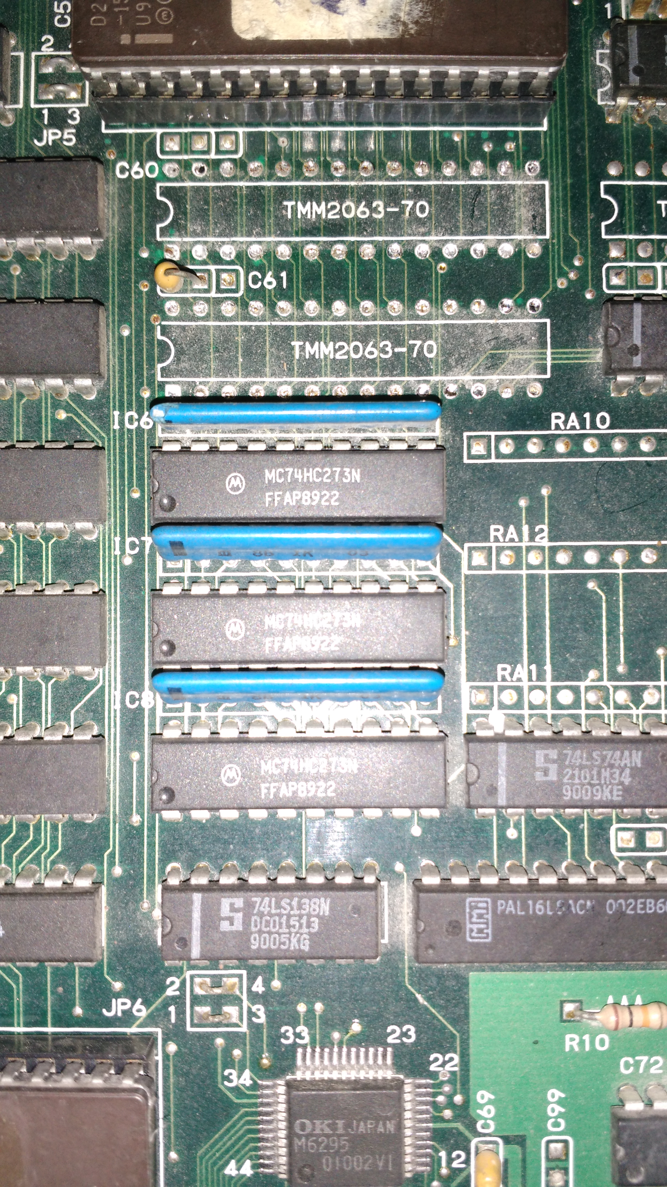
RAM
ROM
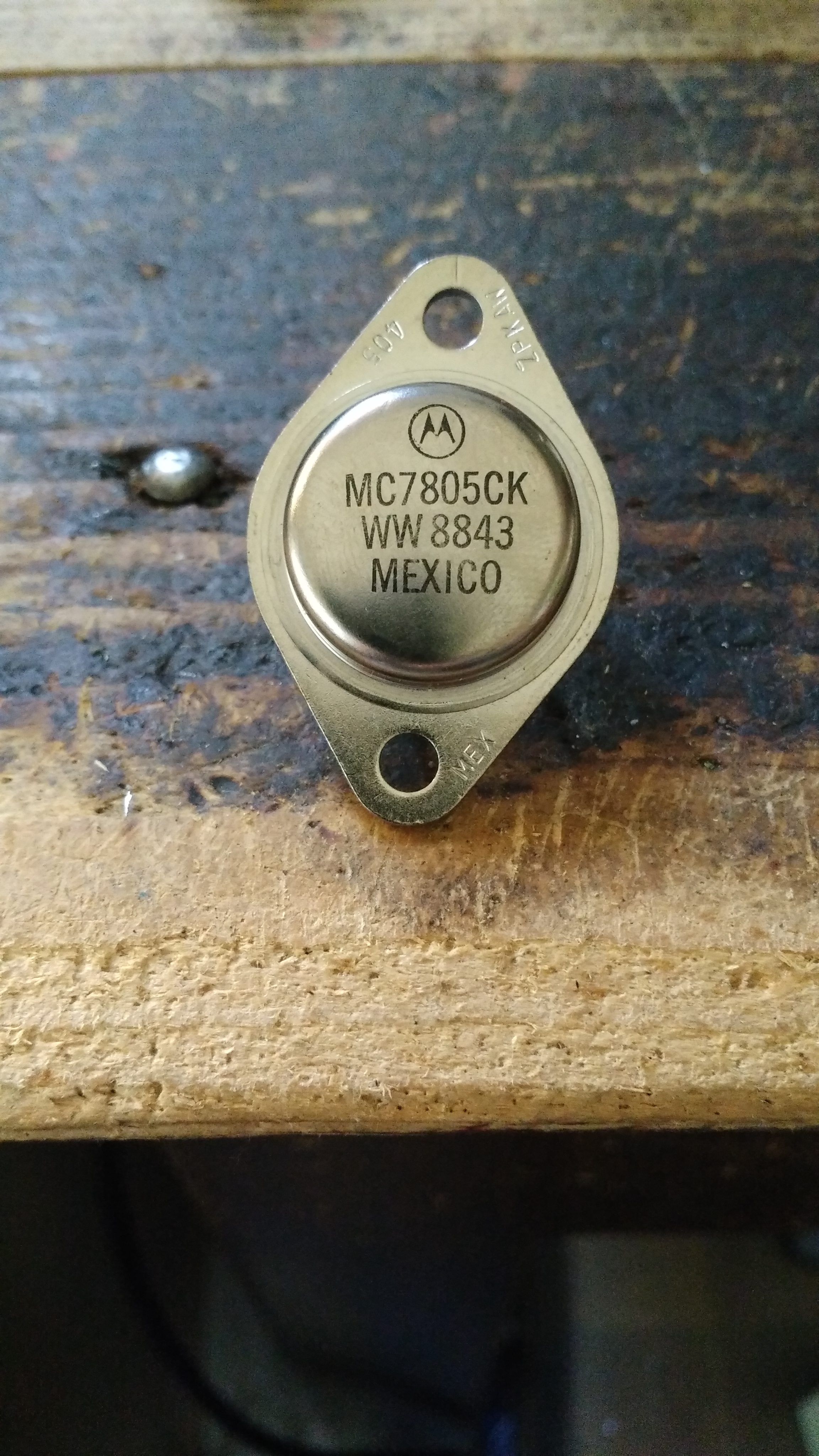
Y2203
MCU
uPD4701
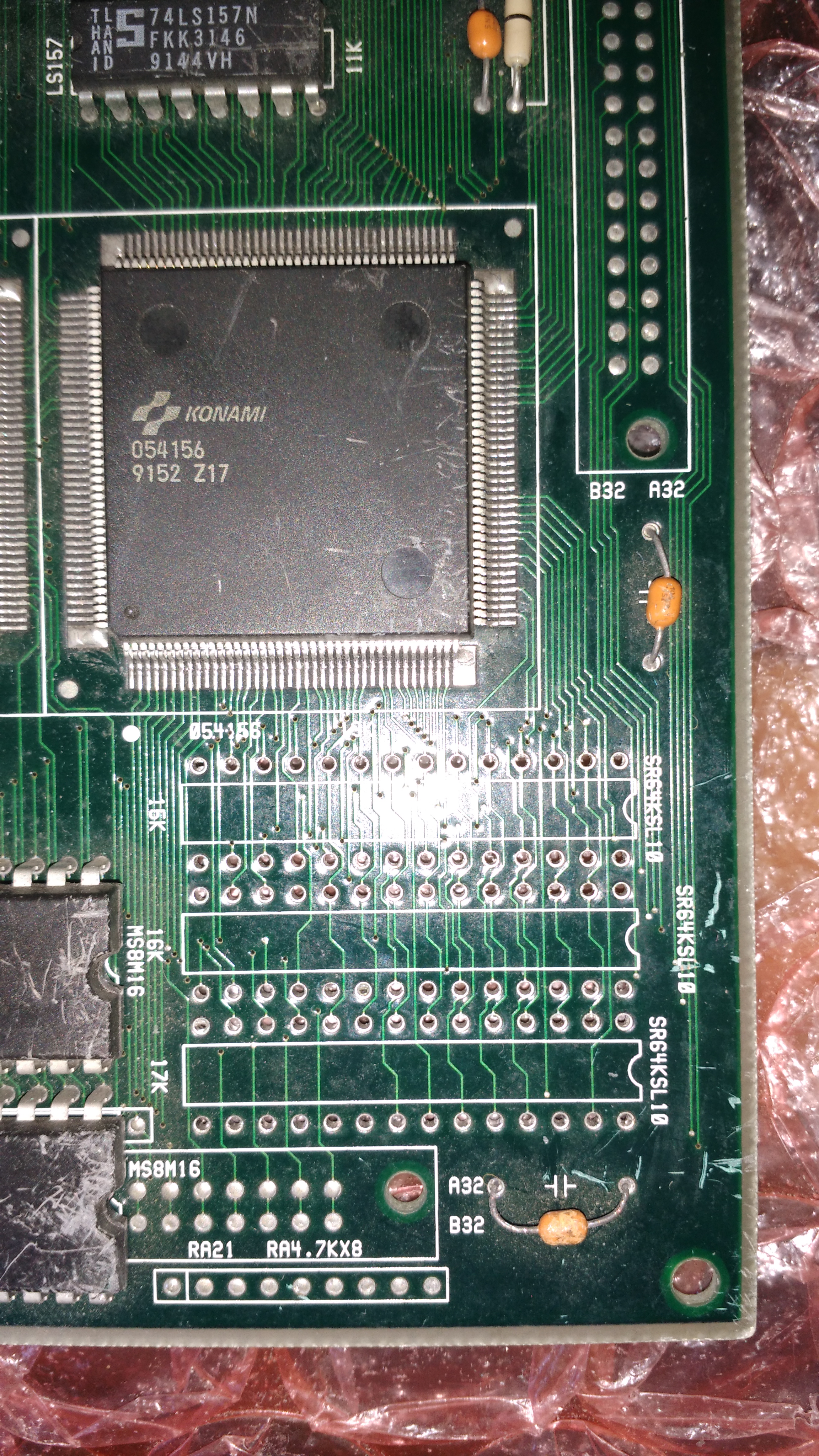
I desoldered and removed them all but I was worried now as the MCU is currently undumped and I wasn’t even sure the game would work even if I replaced all of this.
I fitted a new Z80, RAM, ROM and PAL as I had them on hand. I then set about patching both the main and sub ROM’s in order to bypass security checks and to verify the game worked. It did so I attached the Fluke 9010 to the sub CPU socket and simulated various coin and button presses by writing expected values to the shared RAM.
It was a good start and now I was assured the game would actually work I set about thinking of ways to get around the MCU being dead.
My options were:
-Replace the MCU with a modern one programmed to act similar
-Program my own 8741 from scratch
-Create a PCB to fit in the socket to make necessary connections and bypass certain checks in ROM
I started off attempting to replace it with a more modern ATMEGA MCU. I made up a small adapter PCB which would match the pinout of the 8042.
This didn’t work well at all as the ATMEGA doesn’t have dedicated chip selected lines or any of the other control lines I needed. As a result i scrapped the attempt and decided to start learning 8741 assembly.
I spent quite some time learning the ropes on this one dealing with all its limitations and pouring over the MAME source which simulates this MCU. It really was a great experience for me and I enjoyed it a lot.
Phil Bennett gave me some assistance in setting up a MAME environment to use a real MCU file rather than the simulation and I finally ended up with something that seemed to allow me to boot the game.
I went to test my first attempt but realised that I would need some kind of debounce routine for the coin up processing.
I continued working on the MCU features in the background and started to look at getting hold of the missing chips.
I needed a new Y2203. Without this I have no sound and the game also boots straight into test mode as the Y2203 also processes the DIP’s. For now I was patching this check out too.
Getting the Y2203 was fairly easy and I found one on a scrap board.
I eventually got some 8741 MCU’s for a decent price from eBay and was about ready to test for the first time
Success! Coin up was implemented and buttons were implemented too.
The sticking point was the NEC uPD4701. This handles the spinner inputs and I couldn’t find one anywhere.
Hammy was going to send me one with the next batch of things to dump but Caius came to my rescue sooner and sent me one from a Cabal PCB (thank you Caius and Hammy).
I don’t have any spinners to test controls so I hooked up an Arduino to simulate left and right movement.
From my point of view that’s this PCB fully working. Its taken me months to get to this point but its also been one of the most satisfying things I’ve done in this hobby.
There are some ‘features’ missing from my MCU replacement but I don’t think its anything disastrous. The game no longer caps at 9 credits and the tilt signal doesn’t work within the test mode. There is probably other stuff too but I can work on those if they become a problem. Once it has been tested then I will release it.