Mar 242012
 

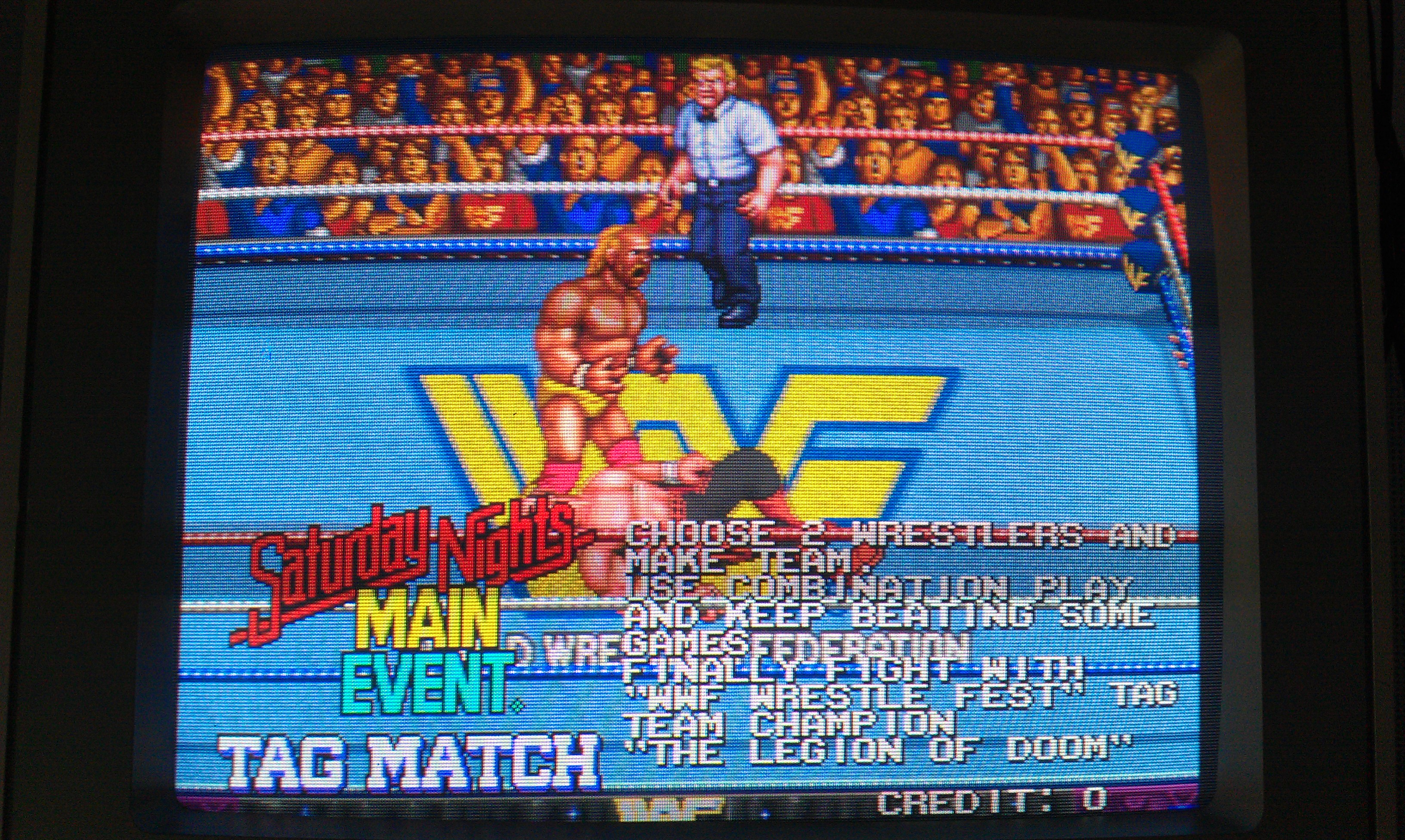
Been after a genuine board of this for a bit now and this one came along. I thought it might be in full working order but once again eBay lets me down.
This one had jailbars through all the main sprites.
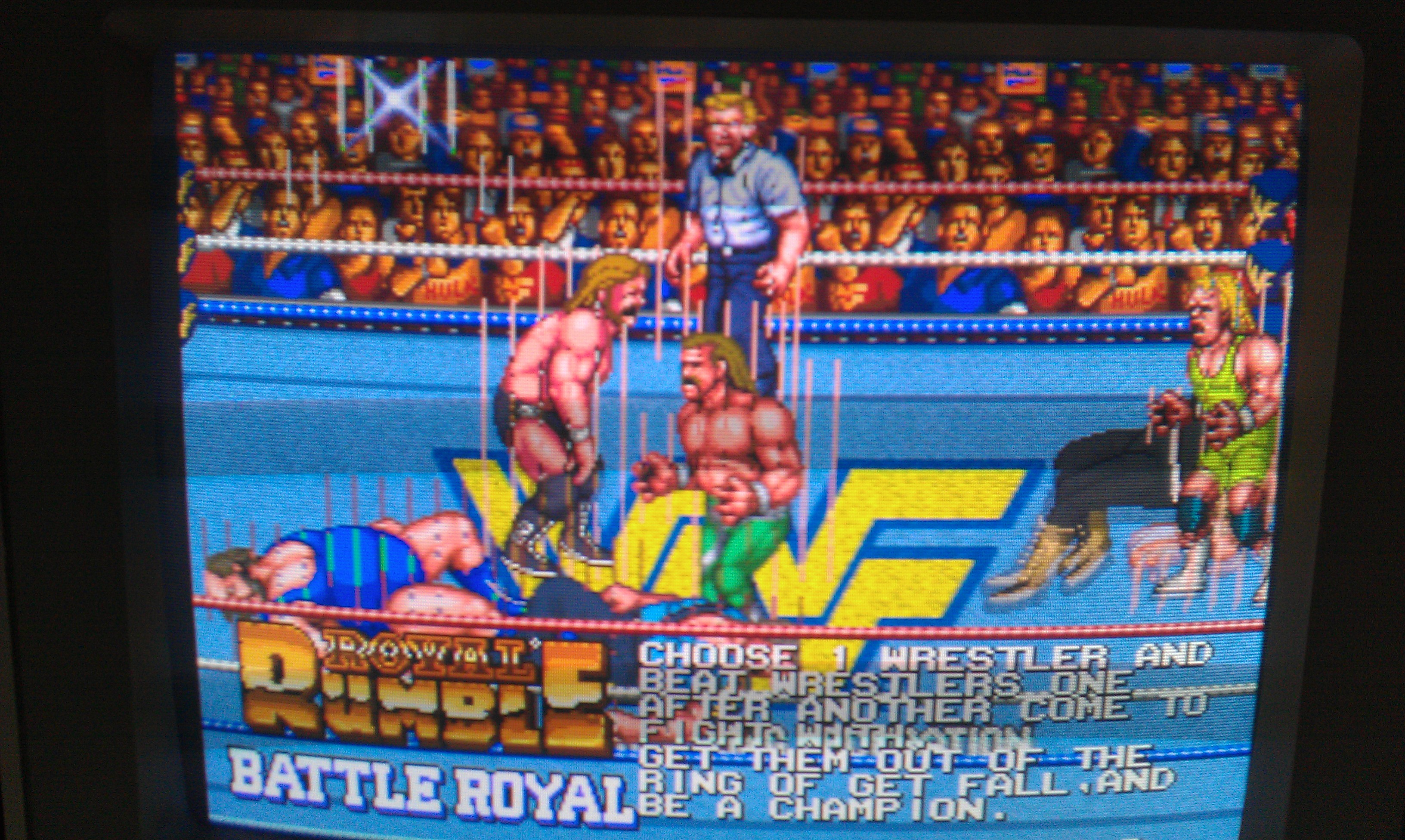
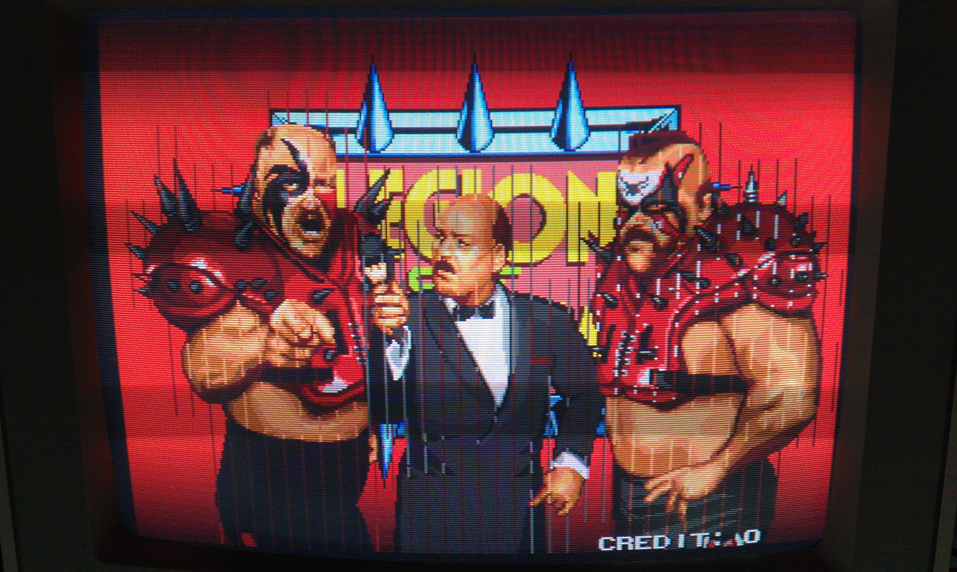
More often than not this is a bad ROM and this was ended up being just that.

In the corner of this board there is a bank of 8 MASKROMs that contain the graphics. Unfortunately none of these are in sockets and as I couldn’t really see anything hugely wrong on the scope.
This game doesn’t have a test mode nor does it carry out any RAM/ROM tests on start up so I wrote a little self test program myself in assembly that tested the sprite RAM at location 0x0c2000 – 0x0c3fff in the address map and simply would display a “P” for a pass or “F” for a fail.
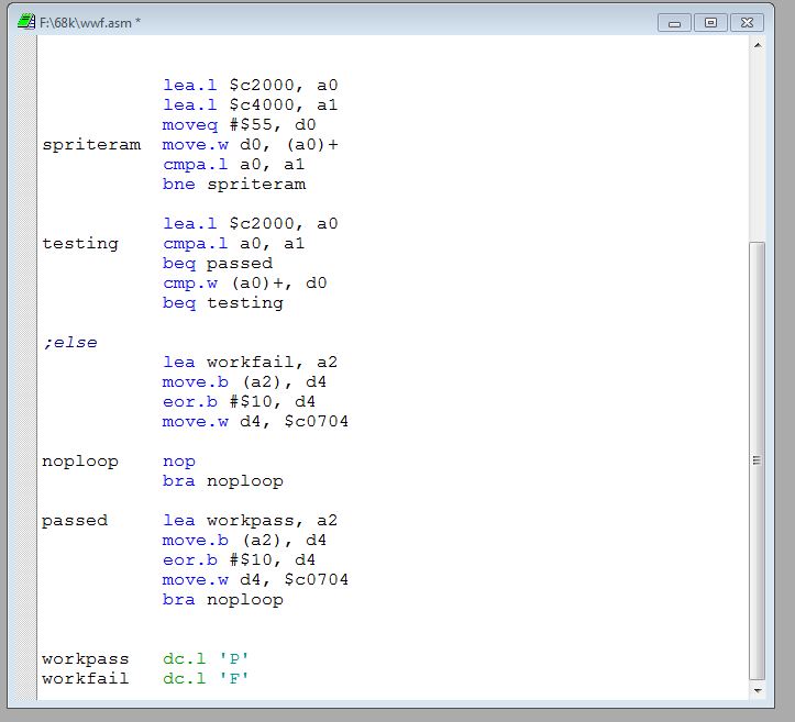
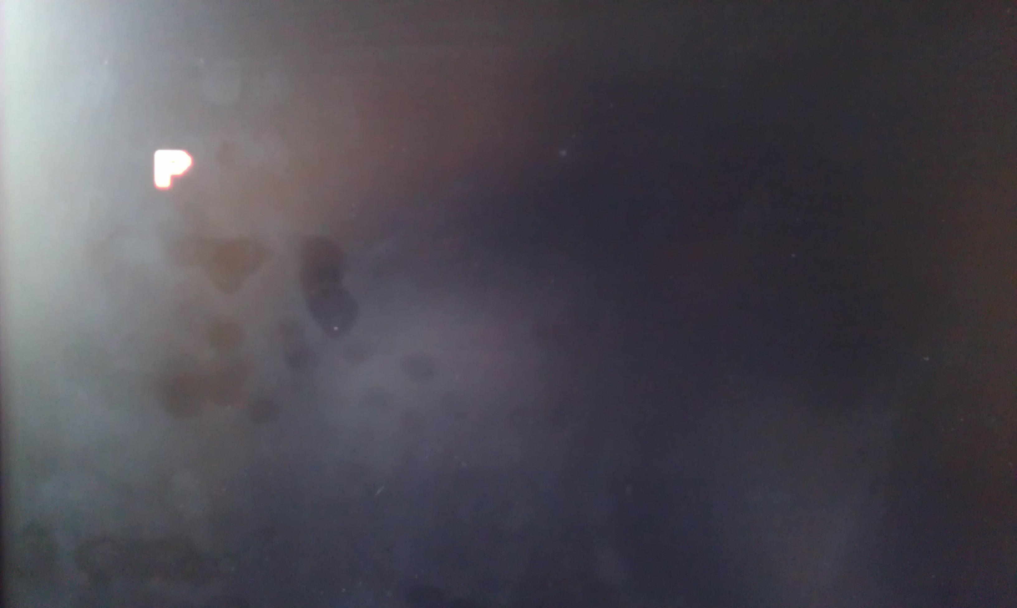
This passed no problem so my hope is for one of the ROM’s to be dodgy as opposed to one of those custom chips.
I set about desoldering them one at a time and checking along the way. After the fourth one I found my problem with a bad ROM dump.
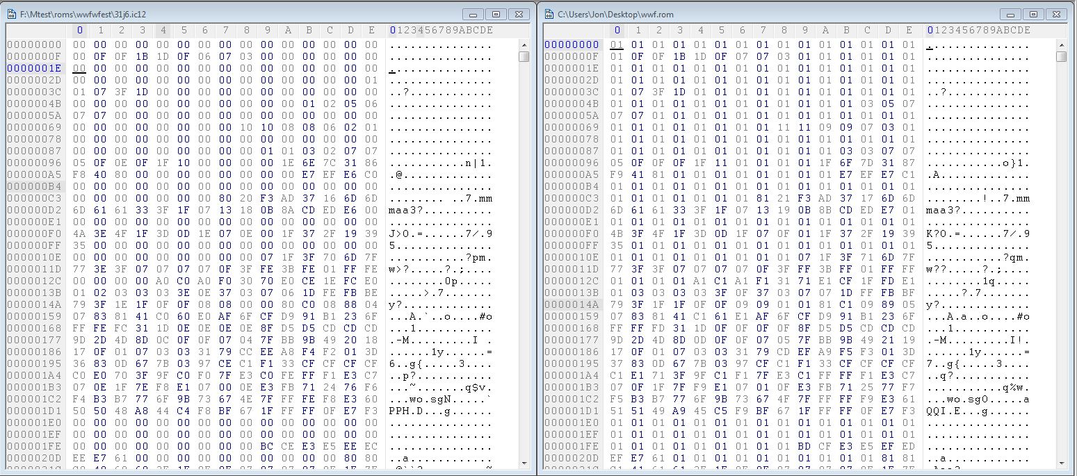
My dump is on the right and the MAME set dump is on the left. As you can see, bit 0 is stuck on.
I fitted a socket and reinstalled the ROM but with data line D0 lifted and checked it out with the scope.
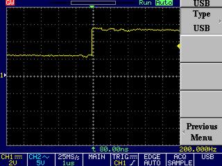
On a closer inspection it shows that the logic level isnt dropping below 2v.
The MASKROMs are pin compatible with 27C080 EPROMs of which I have none. I have ordered some so will hopefully receive it early next week

EDIT: EPROM came today, the game is now fully working
 Posted by at 5:41 pm

Another CPS1 PAL added

 PAL Updates  Comments Off on Another CPS1 PAL added
Mar 202012
 

Balázs emailed me a dump of his KD29B chip from King of Dragons.
His chip was a GAL replacement but he has tested this dump and confirmed it works.
Thanks to him for sending this.

Looking for the Strider (Japan resale) PAL if anyone has it

 Posted by at 4:19 pm

Missing CPS1 PAL dumps

 PAL Updates  Comments Off on Missing CPS1 PAL dumps
Mar 182012
 

Don’t know how I missed these 2 as Ive had the chips for ages.
They are S224B from Final Fight and DAM63B from Daimakaimura.

I know these are already in the MAME sets but I may as well add them myself for completeness.

 Posted by at 10:48 am

Some new CPS1 PAL dumps

 PAL Updates  Comments Off on Some new CPS1 PAL dumps
Mar 152012
 

Got some CPS1 stuff today. There are a couple of populated B boards and a couple of unpopulated B boards.
One of the boards is Quiz Tonosama no Yabou 2 – Zenkoku-ban which I believe is the Japanese version of Quiz and Dragons.
The PAL off this B board is labelled TN2292.

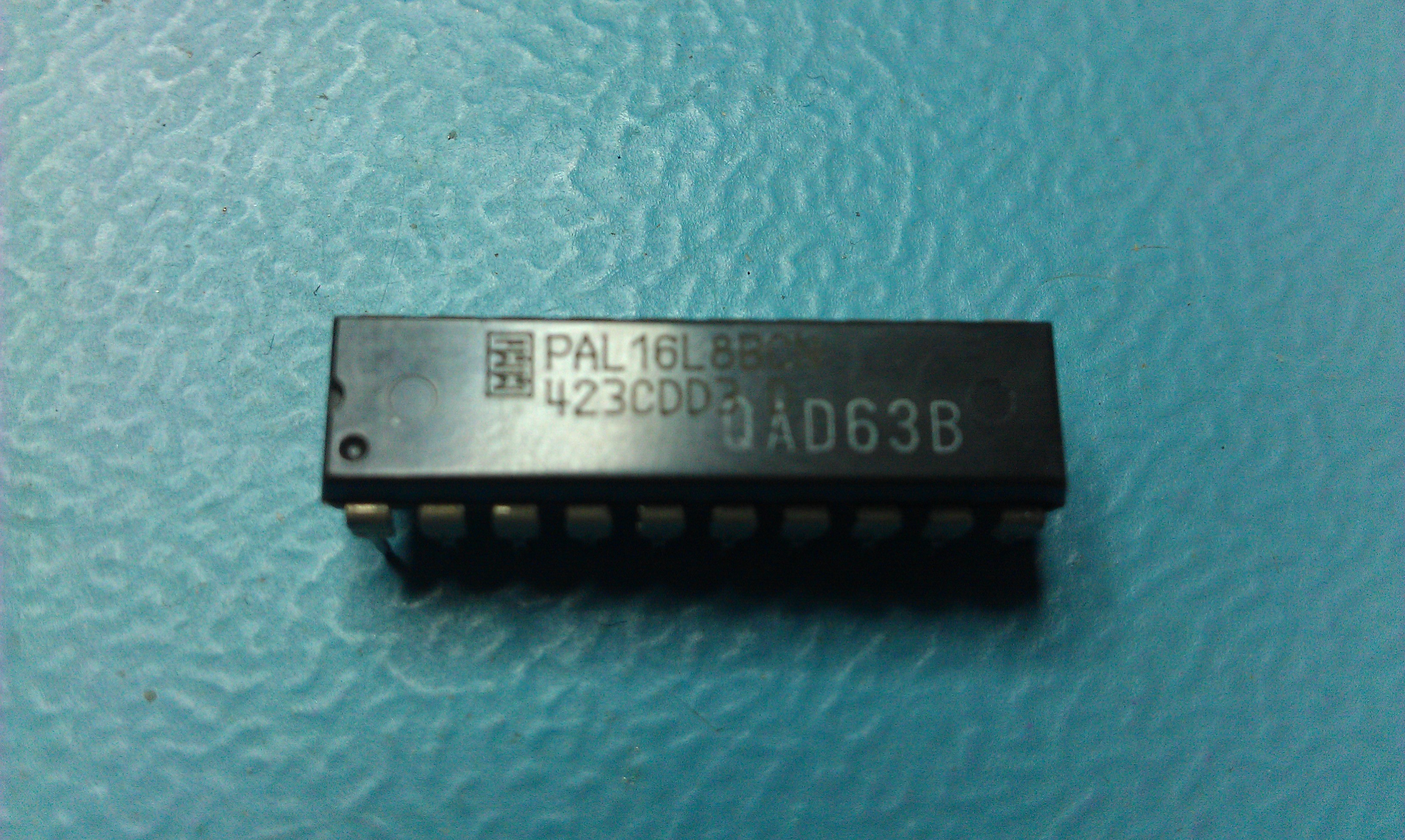
On one of the unpopulated boards was a PAL marked QAD63B which im guessing is from a Quiz and Dragons board. Ive dumped this anyway but it remains untested. I cant even find a reference to it anywhere online.

 Posted by at 7:26 pm
Mar 132012
 

Stiggy gave me an Atari 2600 he had going spare when he came round.
Ive never owned one before but its always been on my list.

The old 2600 only has RF out which is completely rubbish on modern TV’s so it was off to the internet to see what kind of mods exist.
After a short while of checking different sites I came to the conclusion that there is no decent, definative guide for my version of 2600.
My mainboard seemed to be a little different in layout than what the guides were based on.

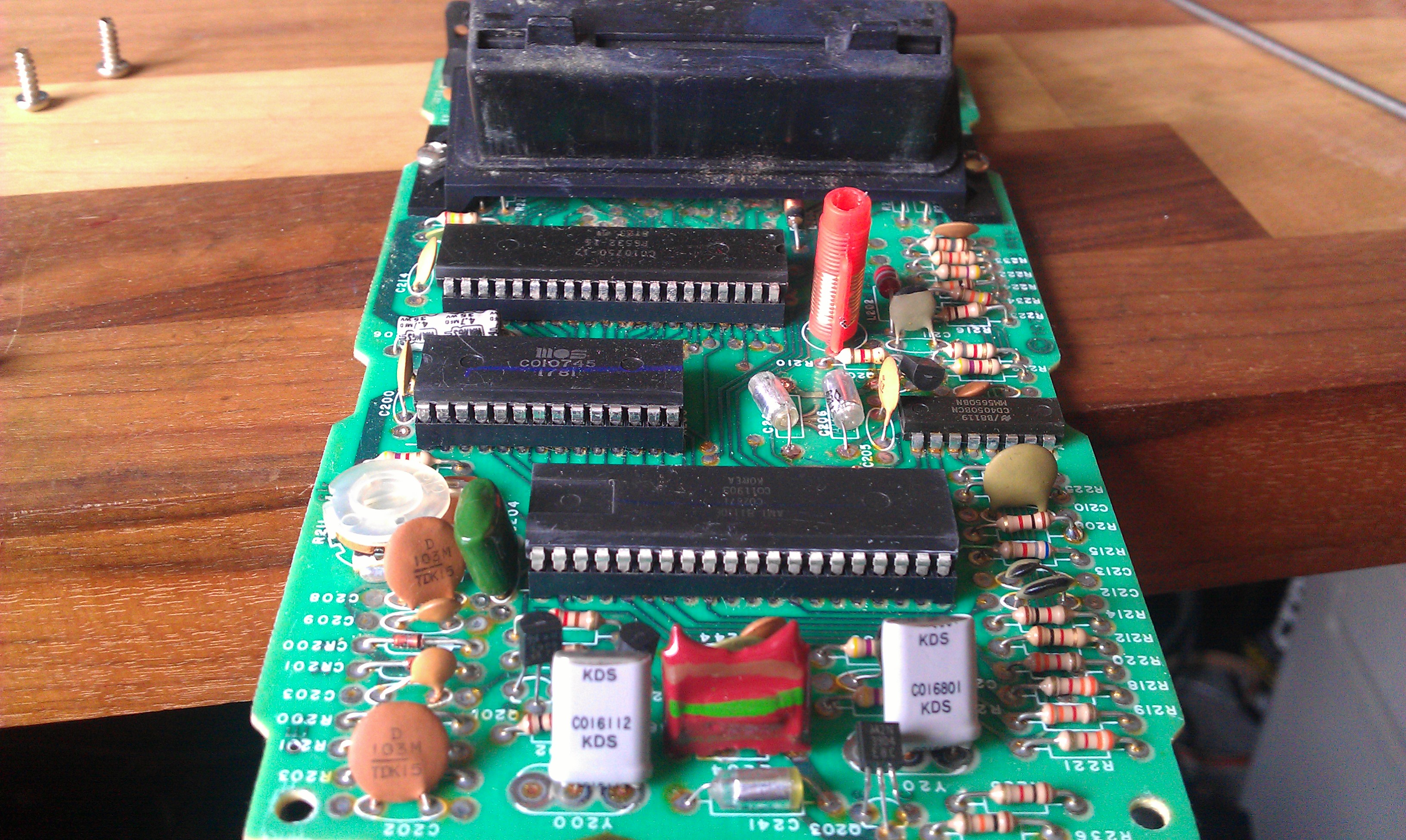
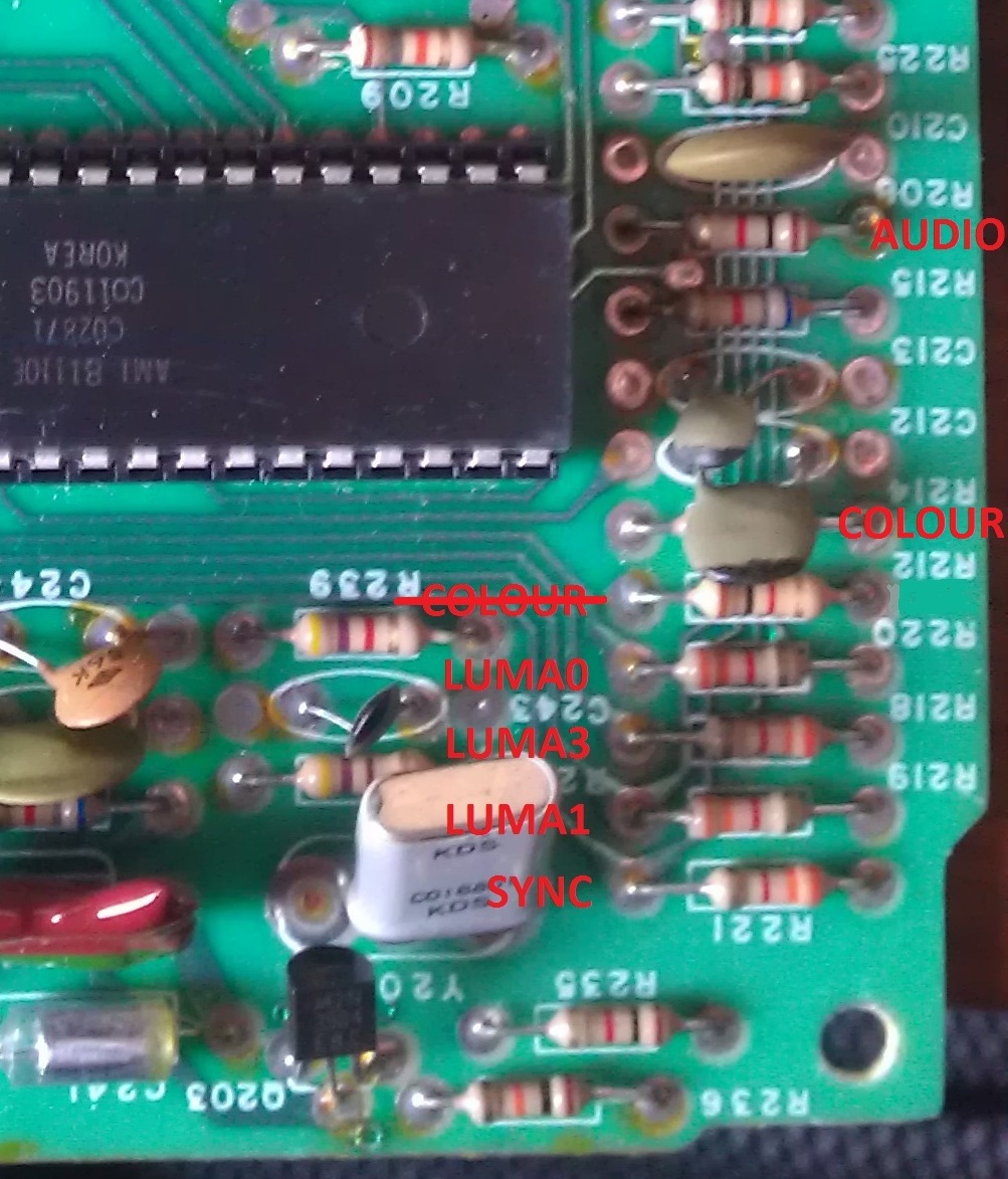
Looking at the other guides they show that the video signals all come from one IC which is standard across all the 2600 models so I traced out the SYNC, LUMA0, LUMA1, LUMA2 and COLOUR signals myself and ran some wires from the points and to the outside world.

As you will see, there is a “COLOUR” label with thats crossed out. This is because I originally followed the circuit through the resistor where I should have followed it from the resistor up to and through the capacitor above it. I ended up tapping into a +5v line by making this mistake so ended up with no signal at all.

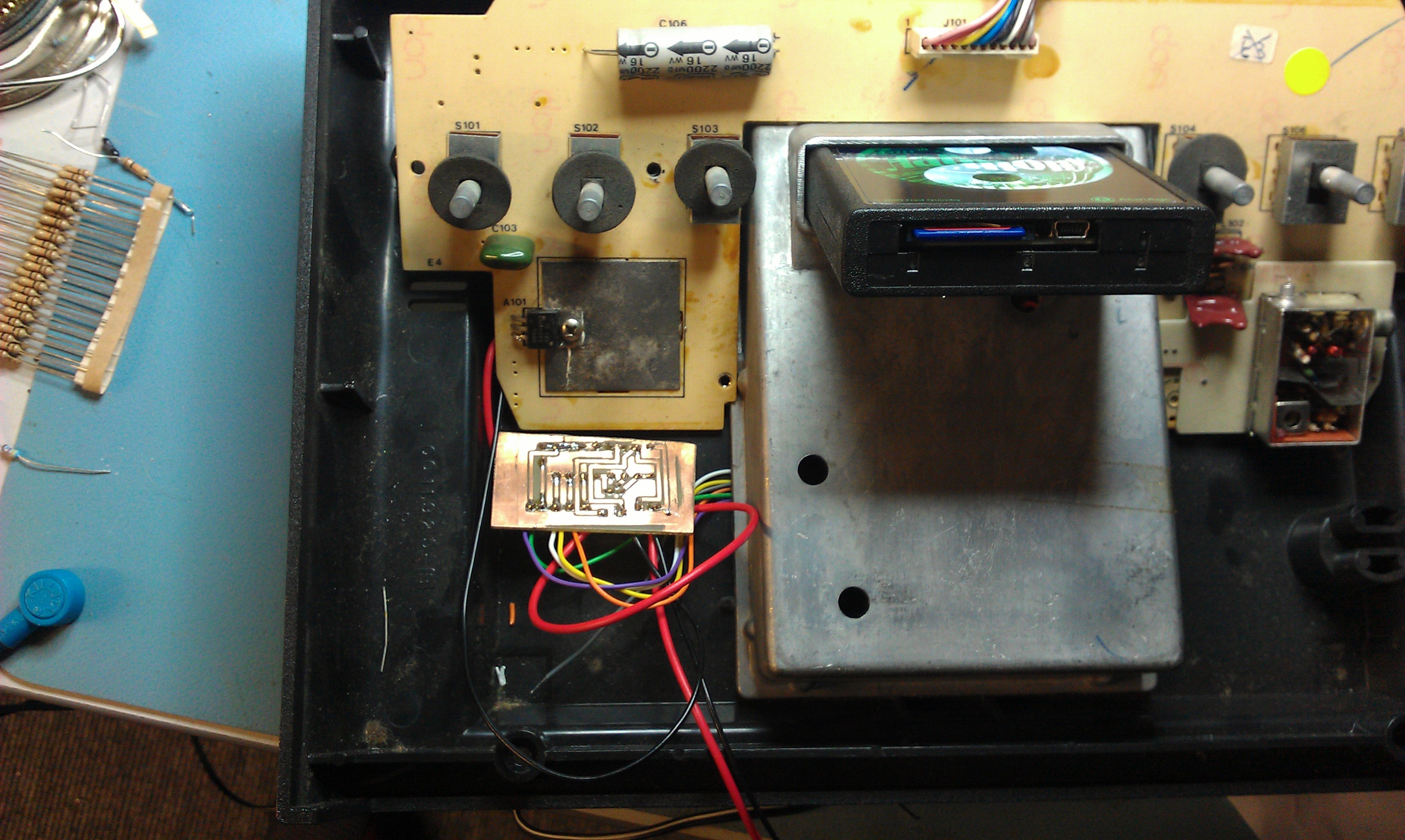
I made a quick design in EagleCAD and etched a board based on a simple transistor based amplifier running the LUMA signals through various size resistors.
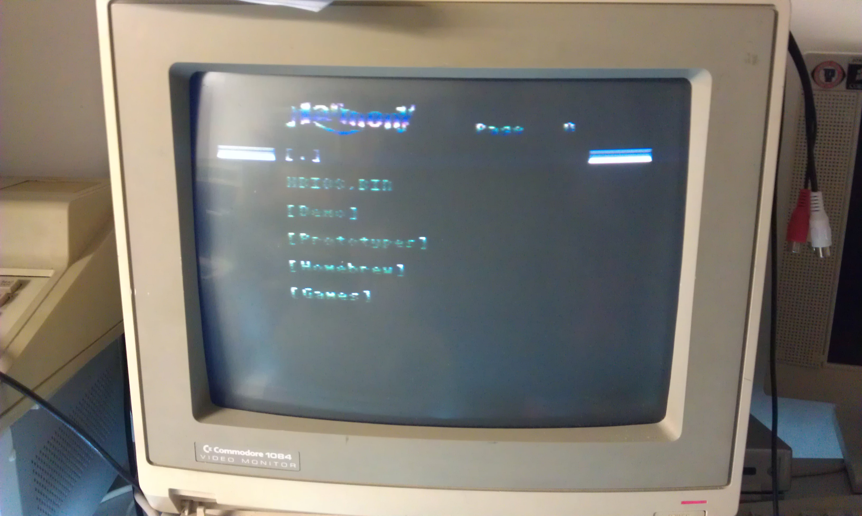
After taking my +5v from the nearby voltage regulator, fixing my mistake that I highlighted earlier and doing a test with a loaned Harmony cartridge I saw a fairly decent image on screen. Its a little dark and this can probably be changed with fine tuning some resistor values but this will be more than acceptable for me.


The pictures don’t look too impressive on the photos but they are a joy compared to RF.
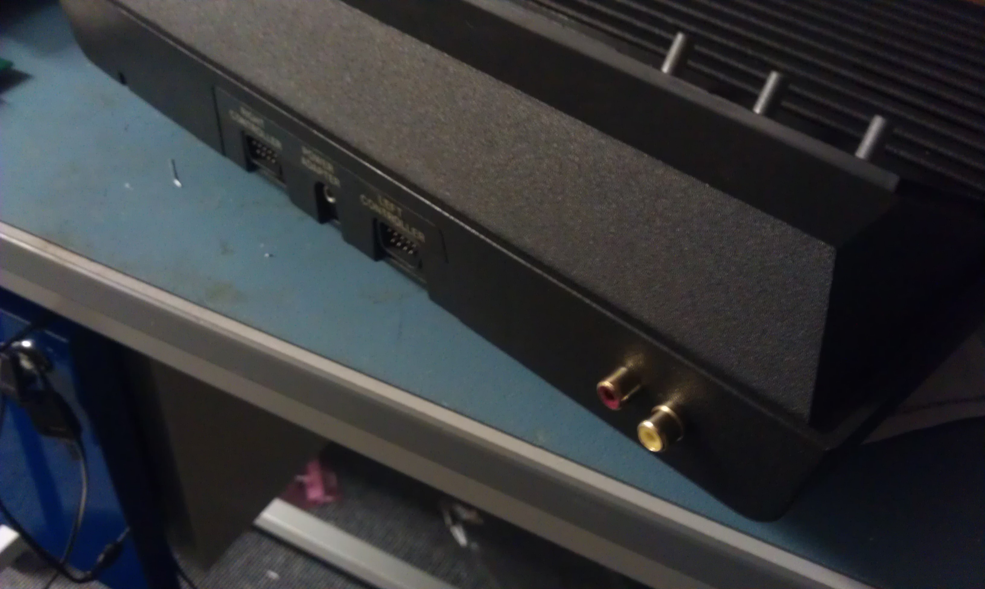
Ive yet to hook the sound up but the wire is there for it, this will be tomorrows job along with properly fitting the phono plugs.

EDIT: Sound is now hooked up and fully working. All phono sockets are fitted. What a nice mod it was.

 Posted by at 8:27 pm