Received this board from a friend which booted to a static screen
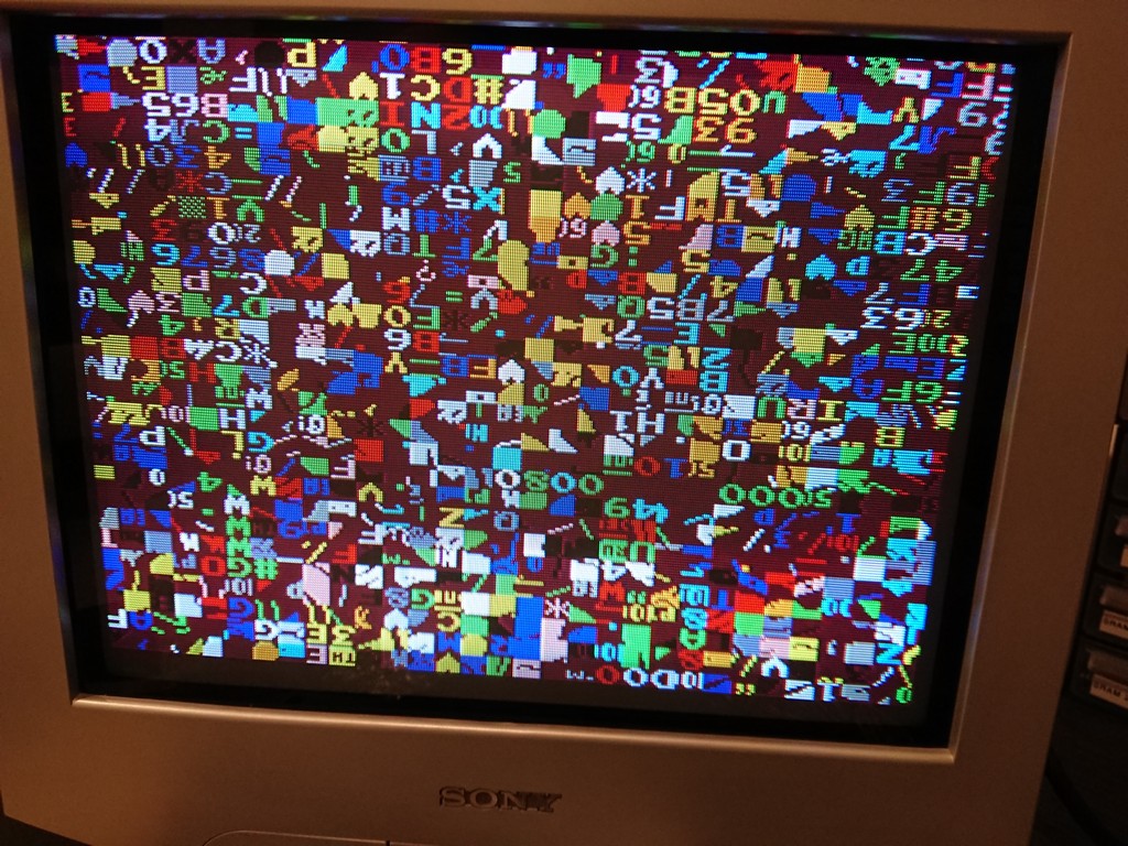
Decided to have a look immediately to the 2k work ram which was a Toshiba which is normally prone to faults.
Changed with an Hitachi 2k
And game 100% fixed with no other errors


Received this board from a friend which booted to a static screen
Decided to have a look immediately to the 2k work ram which was a Toshiba which is normally prone to faults.
Changed with an Hitachi 2k
And game 100% fixed with no other errors
Another custom IC successfully reproduced, it’s the Irem ‘KNA6032701’ , a 42 pin DIP 600mil IC used on M62 (Kung-Fu Master, Lode Runner, Spelunker and other), M75 (Vigilante) and M72 (on some type of ‘M72-B-D board) hardware
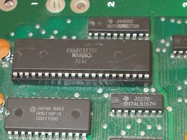
As usual I reproduced it my way by observing how it was reverse-engineered on bootleg boards obtaining in a board layout with pretty same dimensions of original part :
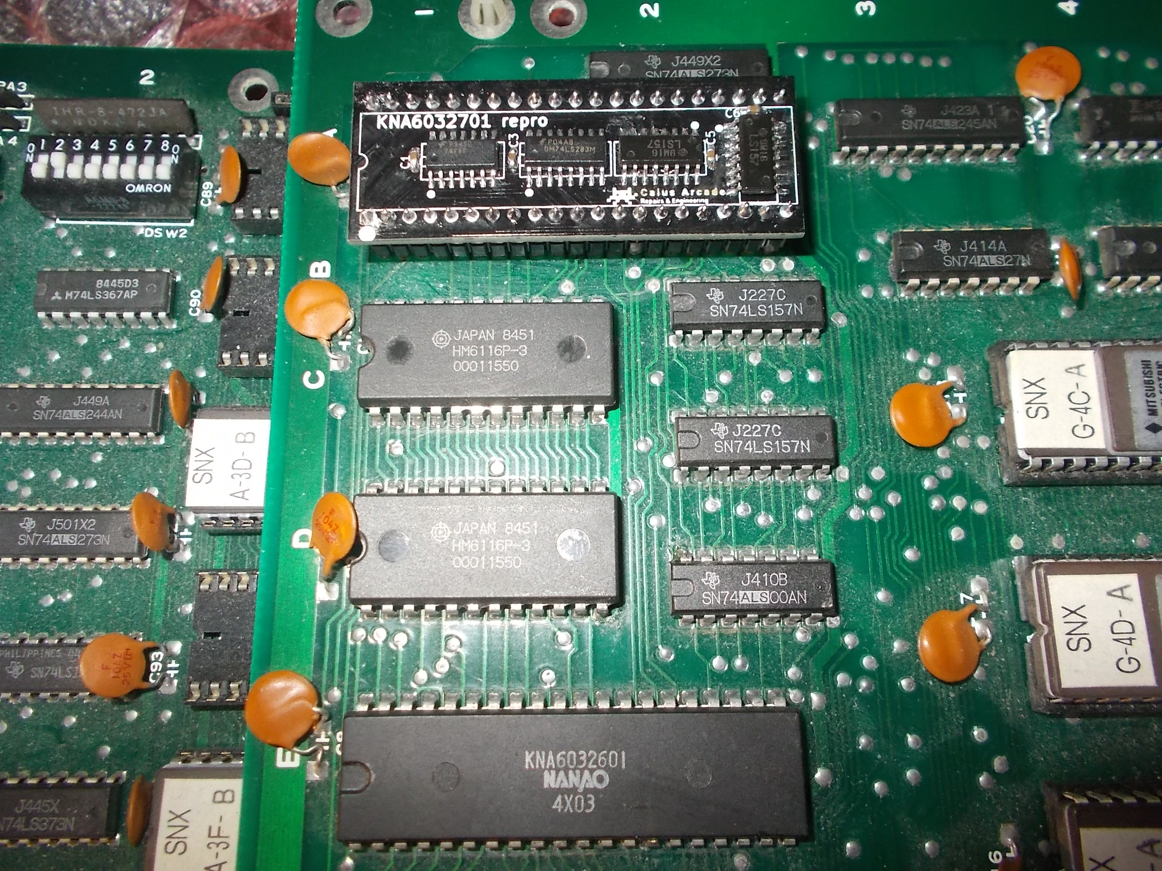
Testing on a Kung-Fu Master PCB :
Received for repair from New Zealand this The New Zealand Story PCB (sorry for the wordplay…), the one layer hardware revision :
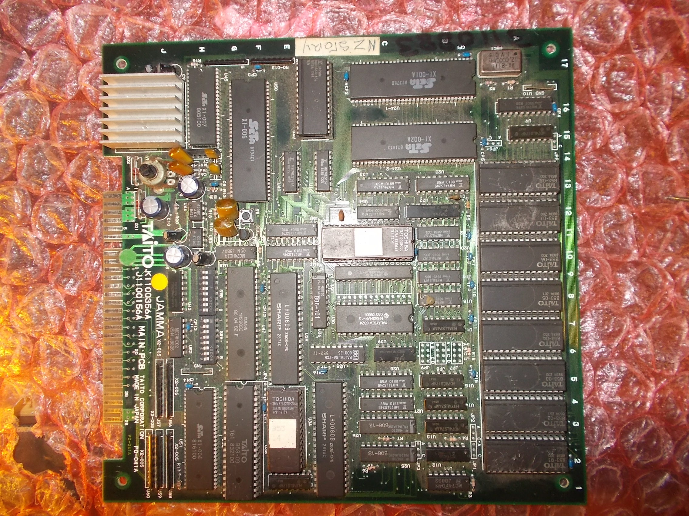
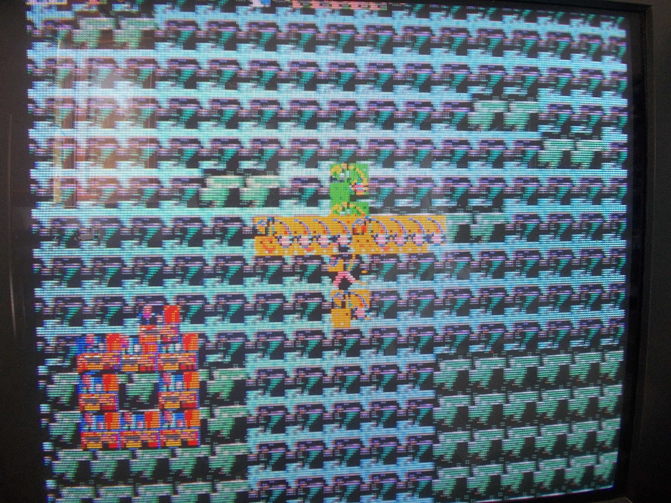
Board booted up but graphics were totally wrong :
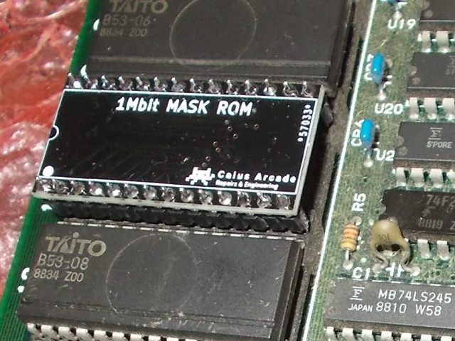
GFX data are stored in eight 28 pin 1Mbit MASK ROMs whose pinout is pretty identical to 32 pin 1Mbit non-JEDEC EPROM (extra pins apart)
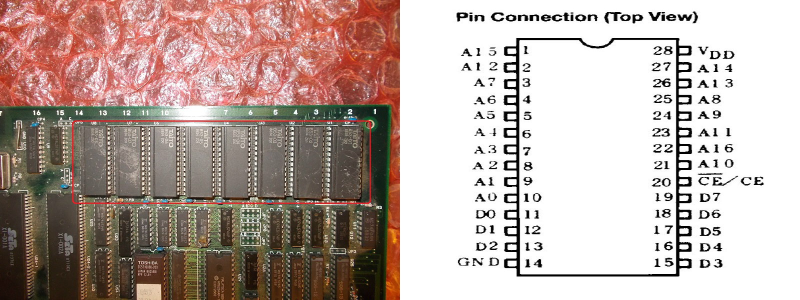
Before dumping them I used my logic probe and found stuck upper address lines (pin 12-13-14-15)
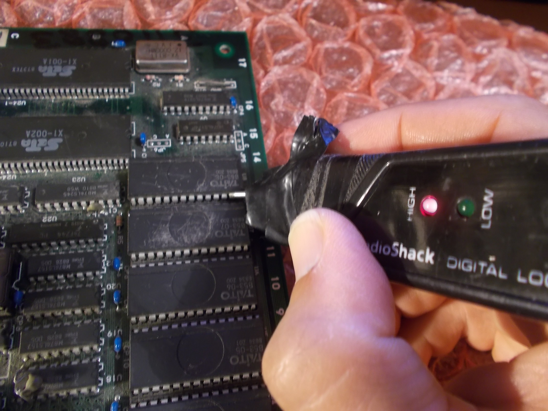
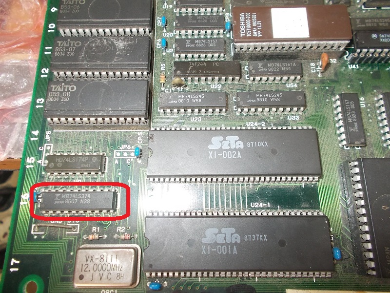
I traced the address lines back to outputs of a 74LS174 @U9 whose inputs were floating, these came from a Fujitsu 74LS374 @U41:
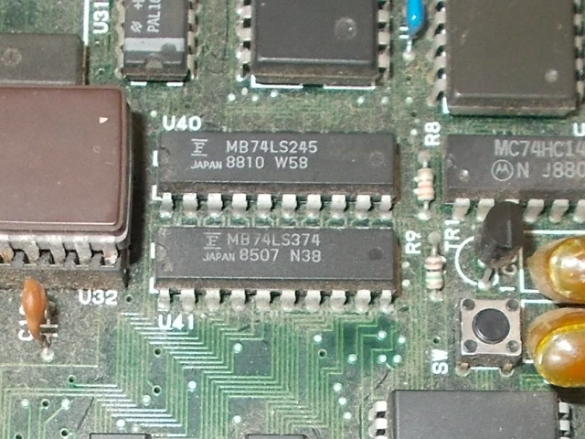
Inputs of it were toggling but all outputs were stuck at undefined voltage level of 1.48V, this is the typical way of failure of Fujitsu TTLs :
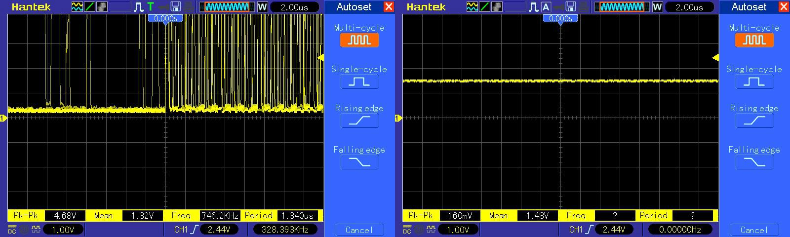
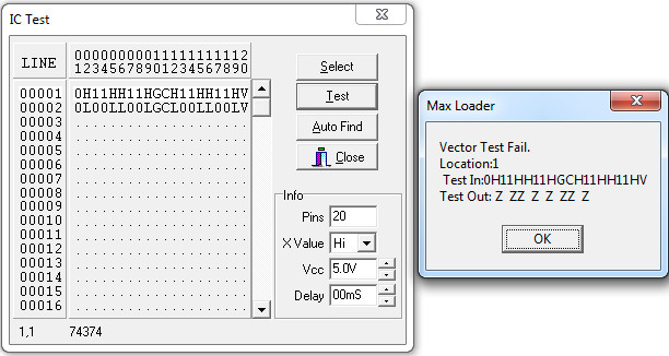
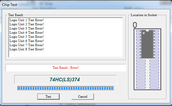
The chip failed the out-of-circuit testing, all outputs were indeed in ‘Z’ (or high-impedance if you prefer) state :
Once replaced the IC the graphics were restored but I noticed some corruption on title screen :
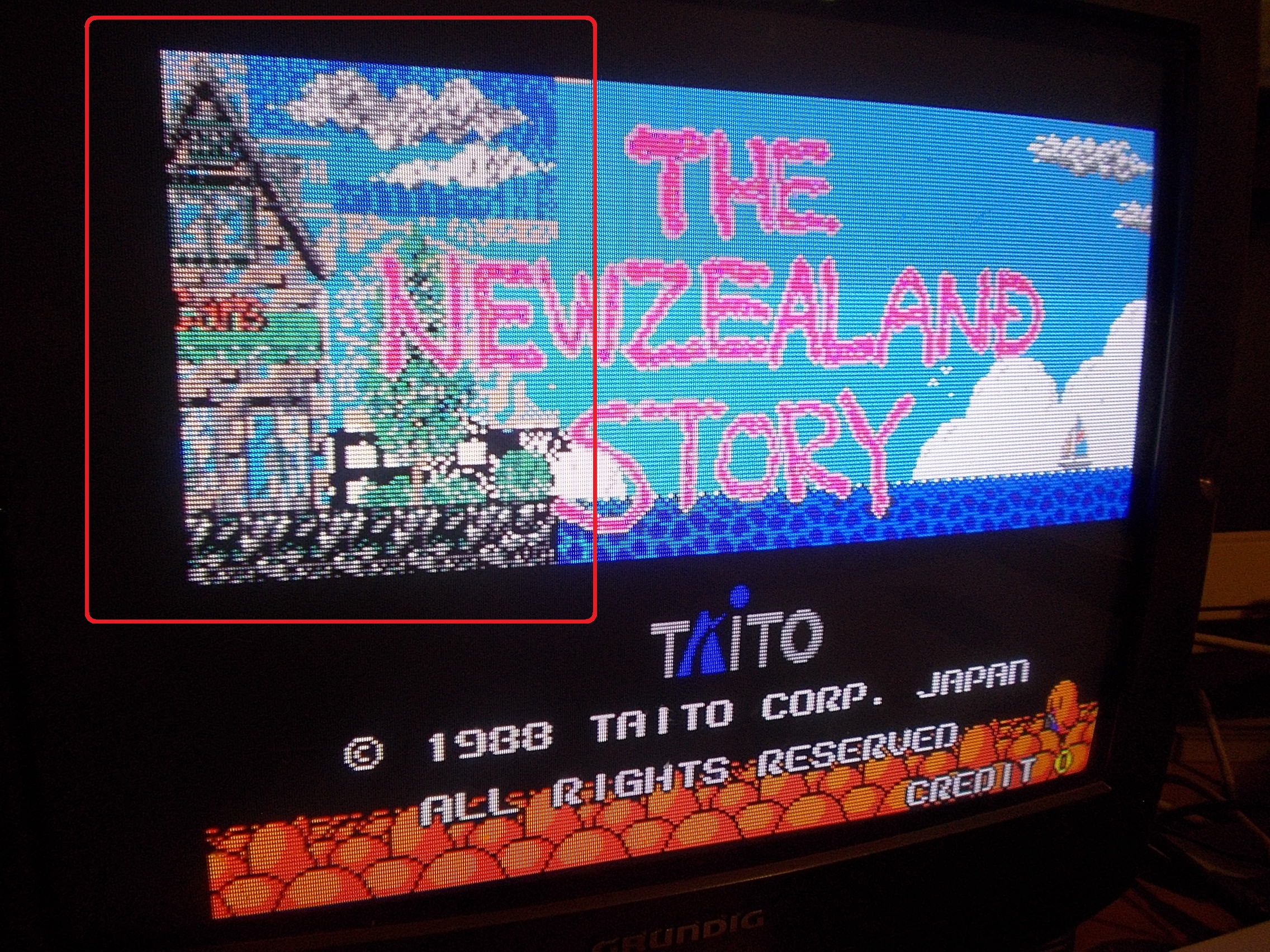
I dumped the 1Mbit MASK ROMs and my programmer complained about the one @U7 :

This was a good chance to use one of my adapters I designed some time ago for replacing the 28 pin 1Mbit MASK ROMs with a TSSOP Flash ROM
But suddenly during power cycling the graphics went bad again :
I quickly pinpointed the fault to another 74LS374 @U10 with floating outputs, another Fujitsu one obviously :
Chip totally failed the out-of-circuit testing:
Graphics were now perfect so I started a game but controls didn’t work, the main character of both players moved by itself:
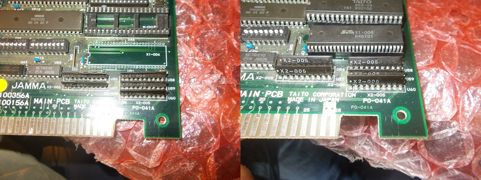
Looking at hardware I figured out the I/O circuit.The inputs from JAMMA connector go to some custom resistor arrays marked ‘X2-005’ and then signals are routed to a 52 pin SDIP custom chip marked ‘X1-004’ that handles them :
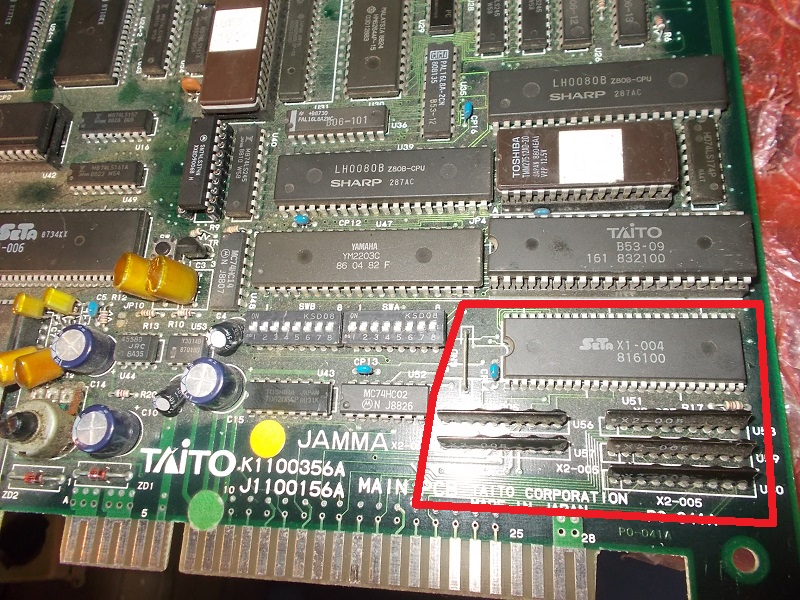
Resistor arrays did their job by pulling-up the signals and then routing them to the custom so most likely the ‘X1-004’ was bad.I played the card of replacing it but I had to struggle before finding a good spare as it seems this custom is quite prone to failure.I tried two donor parts but they were faulty until I caught the good one:
This fixed the controls and board completely.Repair accomplished.
The site has now been switched to use SSL. Hopefully this works for others and not just myself.
Thanks
Some time ago Team Europe has had success in resetting the security fuse on 8751 MCU’s.
See these posts
Post 1
Post 2
Post 3
While looking for something else among my own hoard of stuff I came across an old Choplifter PCB that has been used over the years for parts but the MCU was still present.
Inspired by the work of Team Europe I decided to give it a go myself.
Removing the cap was a bit tricky because I don’t really have the tools required for the task. I ended up using a small file and making a lip so I could fit a screwdriver under it and pry the lid off.
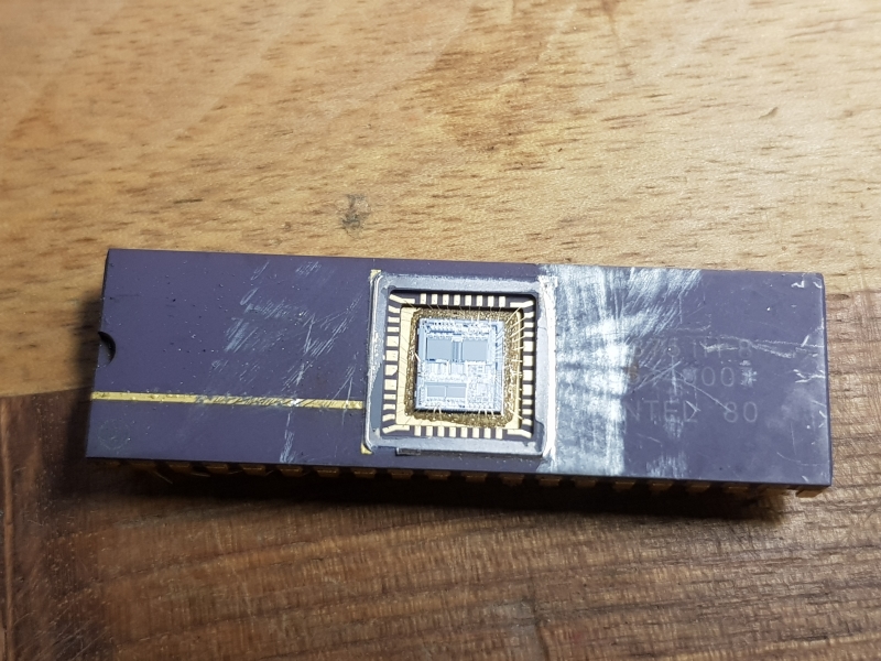
Adding some nail varnish generously donated by my daughter and we have this familiar sight.
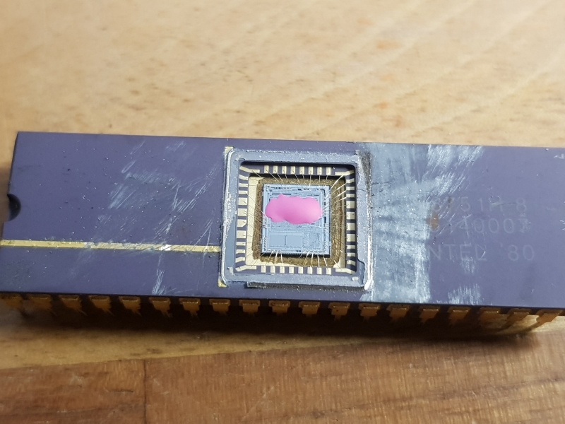
I threw it in the UV eraser for 15 minutes and tried reading.
I got data back but was it good?
Comparing to the one currently in MAME I had 1 byte different at address 0x100.
Now, looking at the MAME source we can see that it applies some software patches.
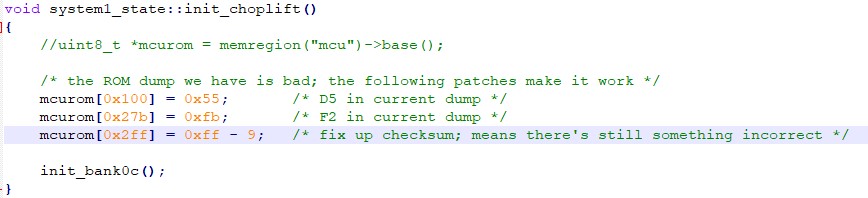
The byte at address 0x100 is indeed on of the patched areas.
Not sure why address 0x27b is also patched. Without this one applied there is no need to compensate by patching address 0x2ff.
Anyway I removed these patches from MAME and booted with my dump and all seems to work just fine. Hopefully the MAME team will agree its a good dump and add it too.
Thanks to Team Europe