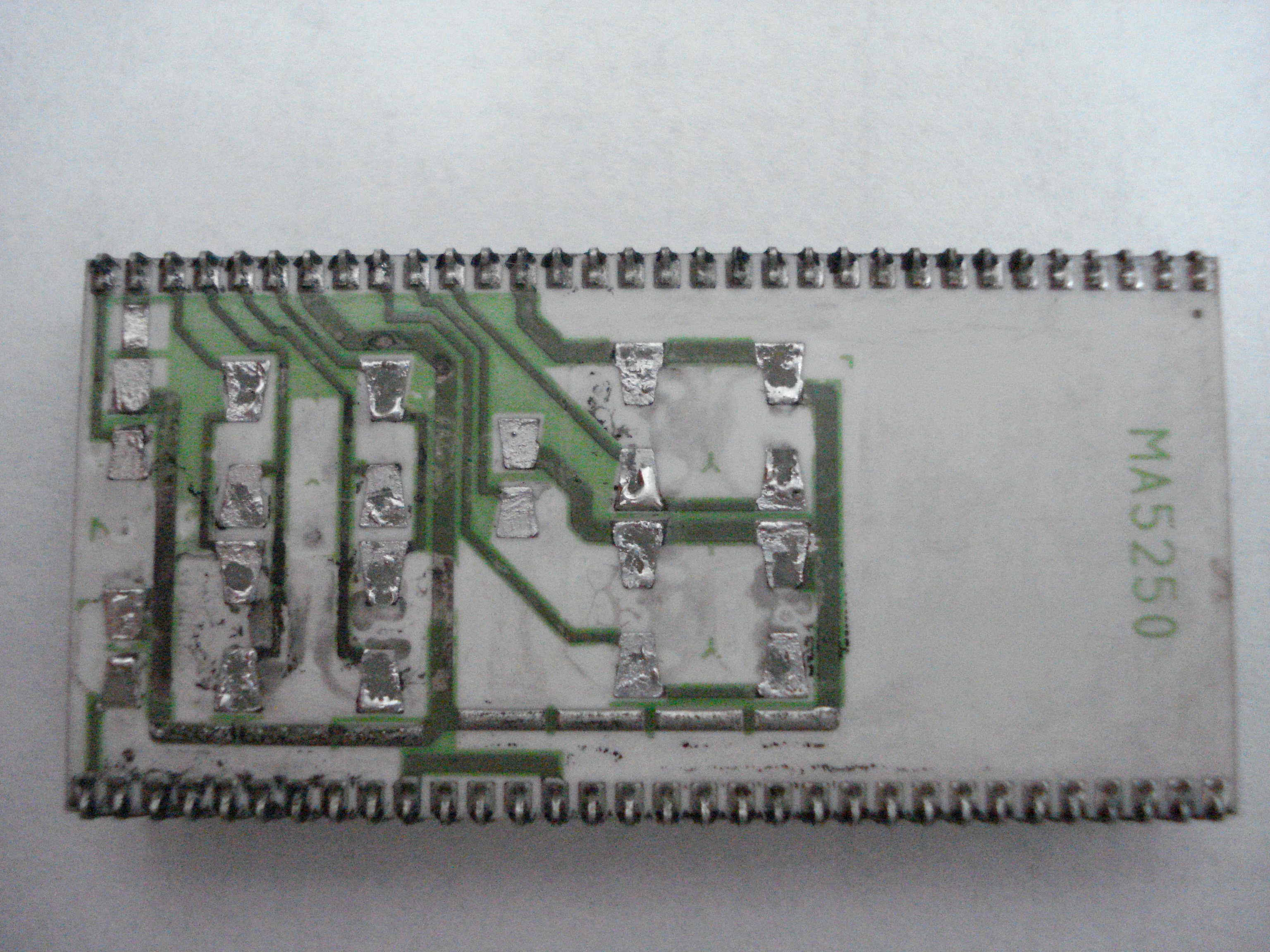
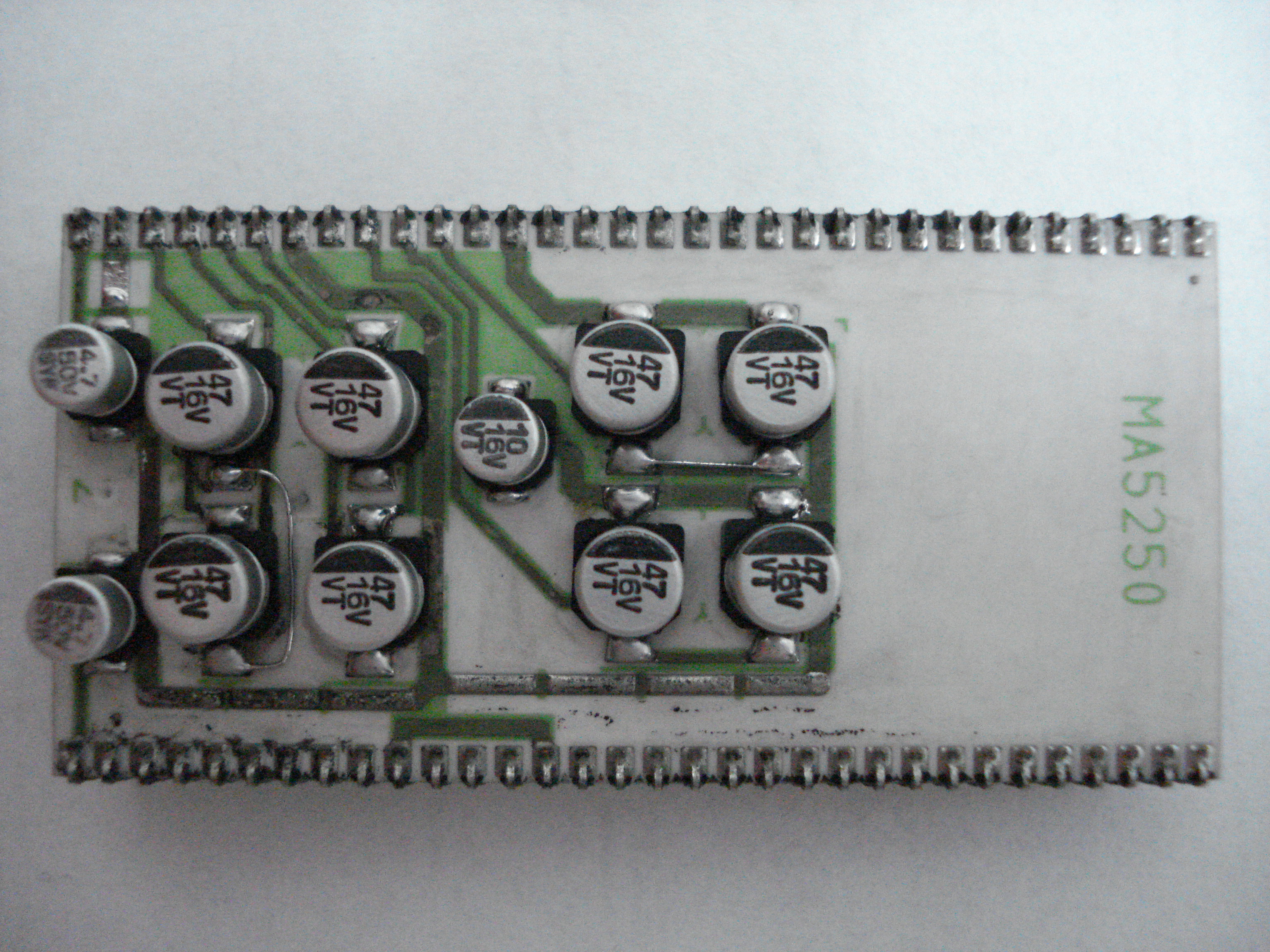
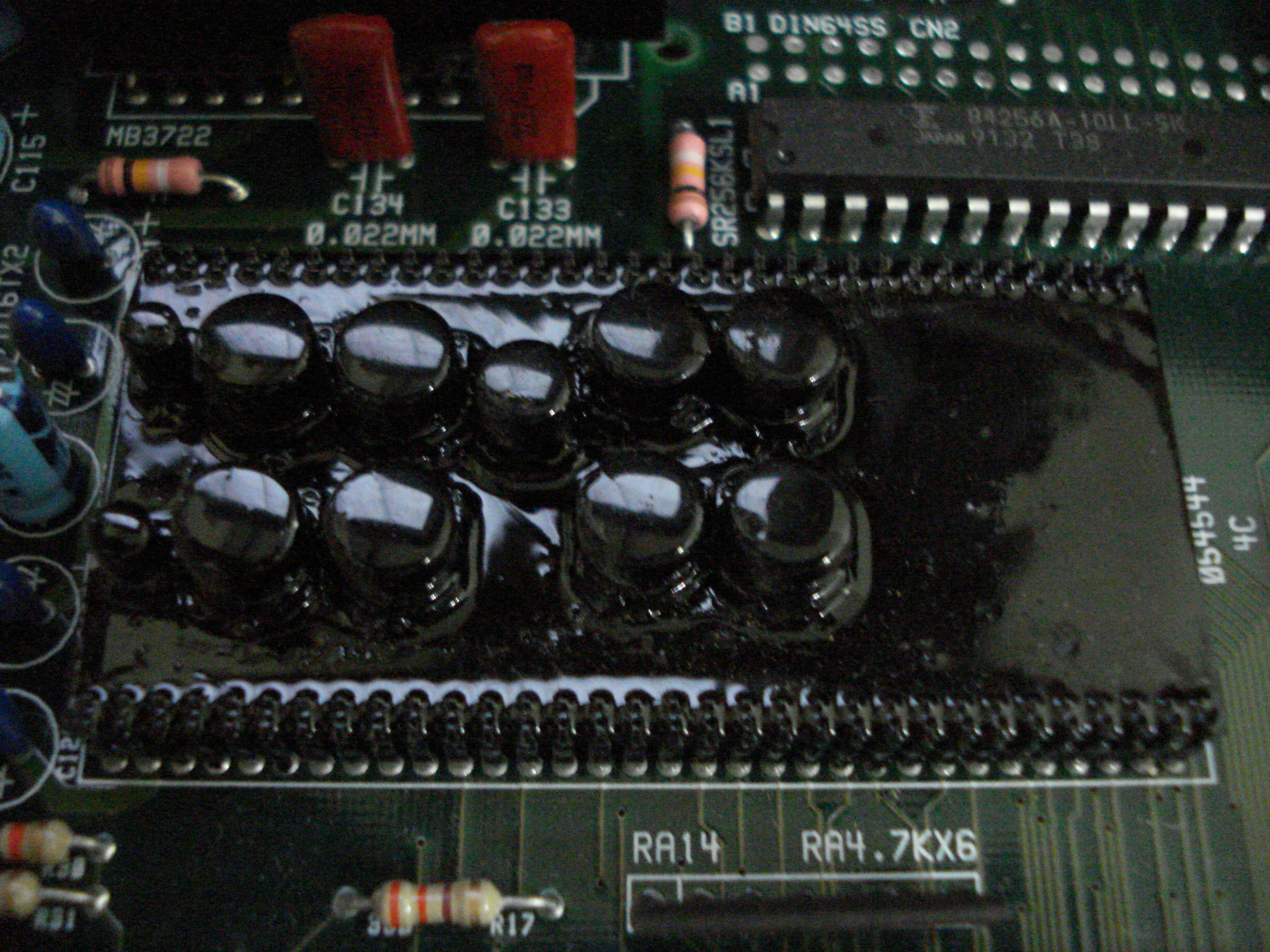
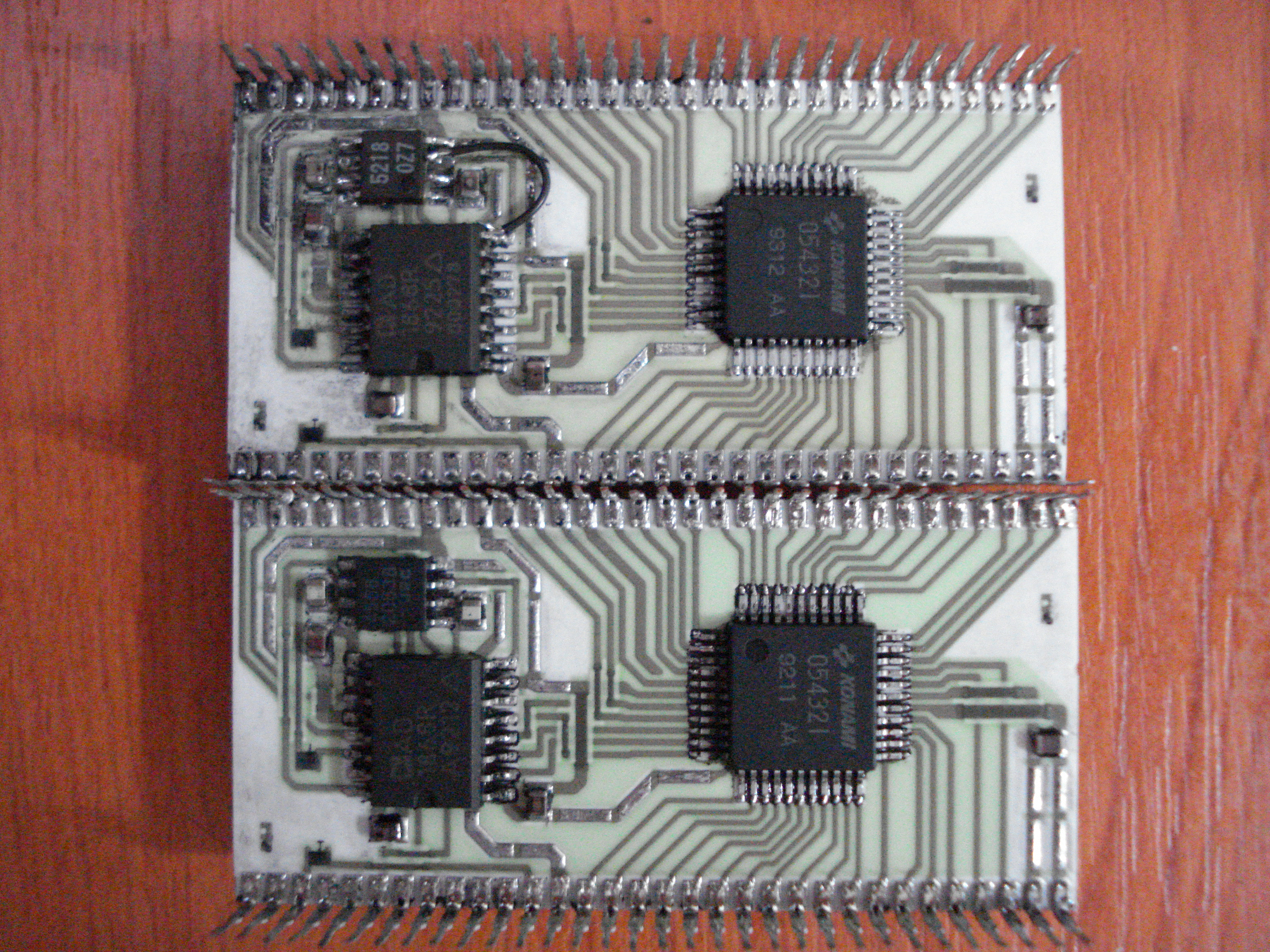
Some days ago Dragos sent us some pictures of his Konami hybrid sound modules reworking.As most of you already know, this customs are used in many Konami arcade games.Specifically the ‘054986A’ is used on Lethal Enforcers, G.I. Joe, Metamorphic Force, Run & Gun, Premiere Soccer, Bucky O’ Hare, Violent Storm, Monster Maulers, Martial Champion, Mystic Warriors, Gaiapolis and Wild West C.O.W. Boys of Moo Mesa while the ‘054544’ is present on X-men and Xexex.A common fault on these customs concerns the SMT electrolytic capacitors that after some time start to leak ‘eating’ traces of the module.What Dragos did was to literally ‘undress’ the modules by removing the black paint using this paint stripper (that you can find in your country under a different name) revealing in this way all the traces and connections on top and bottom layer.Needless to say that this is really useful for everyone who wants to troubleshoot the modules.But, here are the pictures for a better understanding.Let’s start with the ‘054544’:

A nice black repaint is what it takes after a recap…
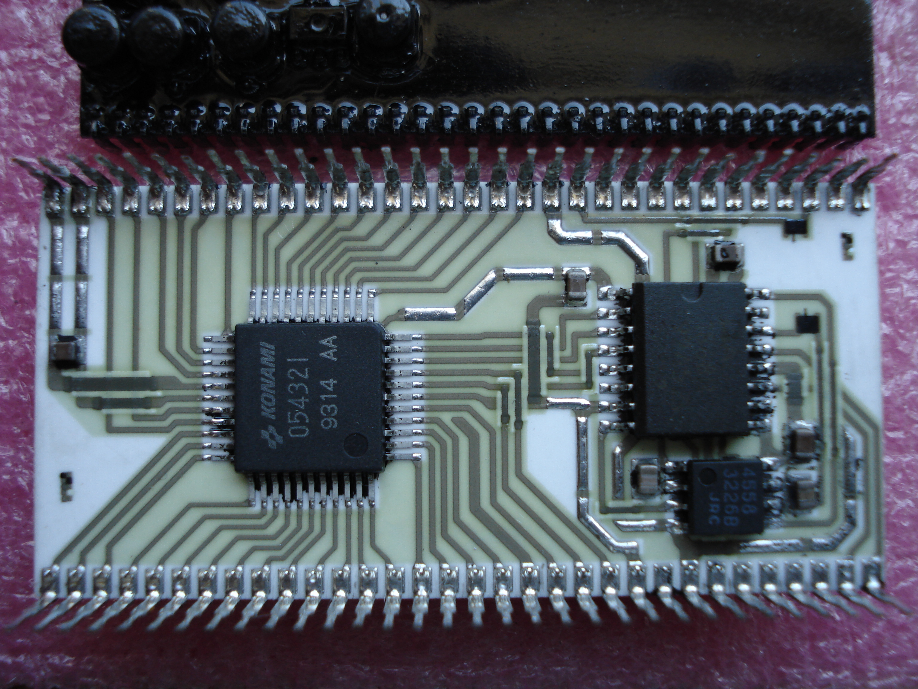
Here is below the ‘054986A’ in all its glory:
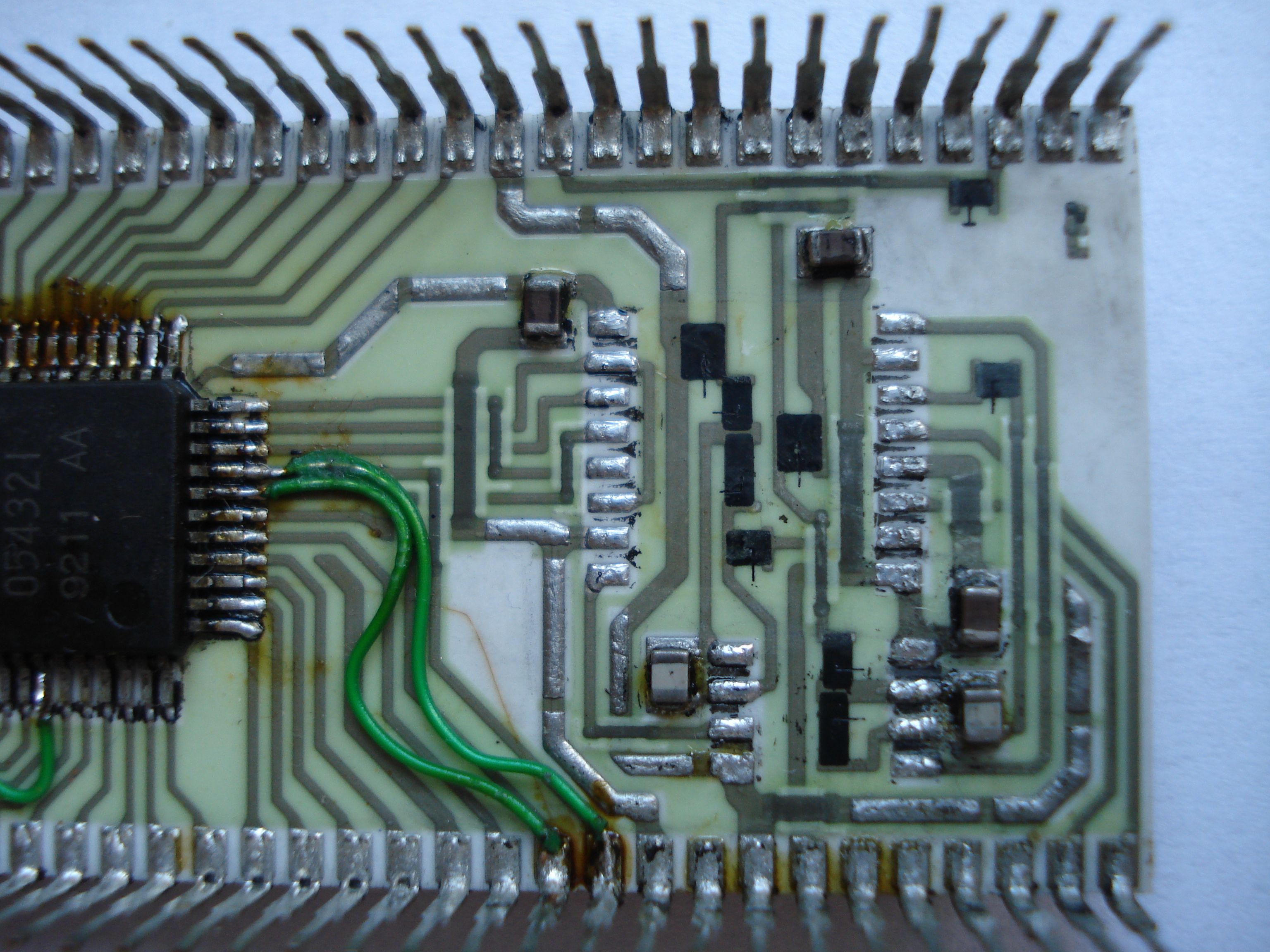
Above, a close up of jumper wires needed to patch some broken connections
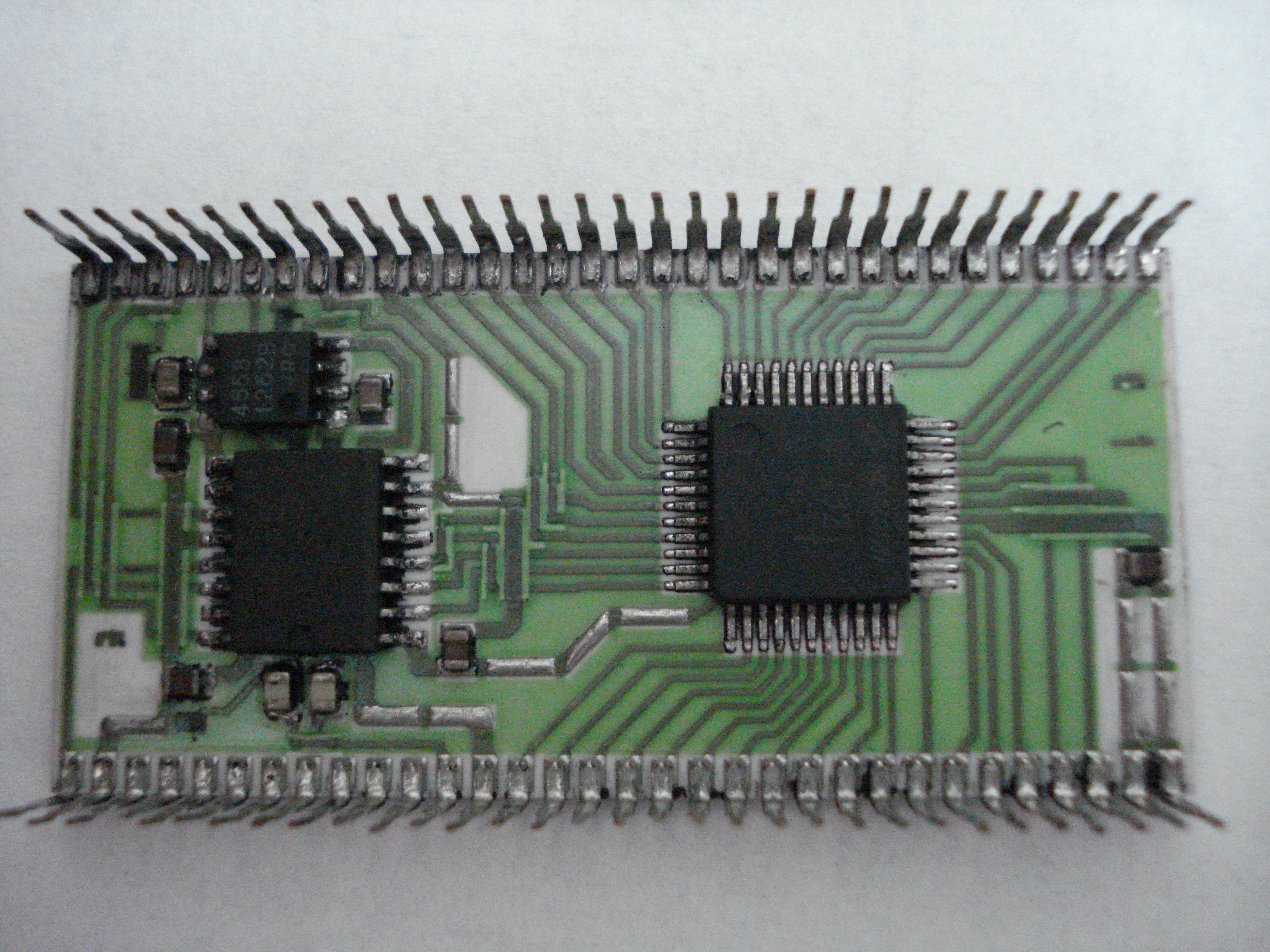
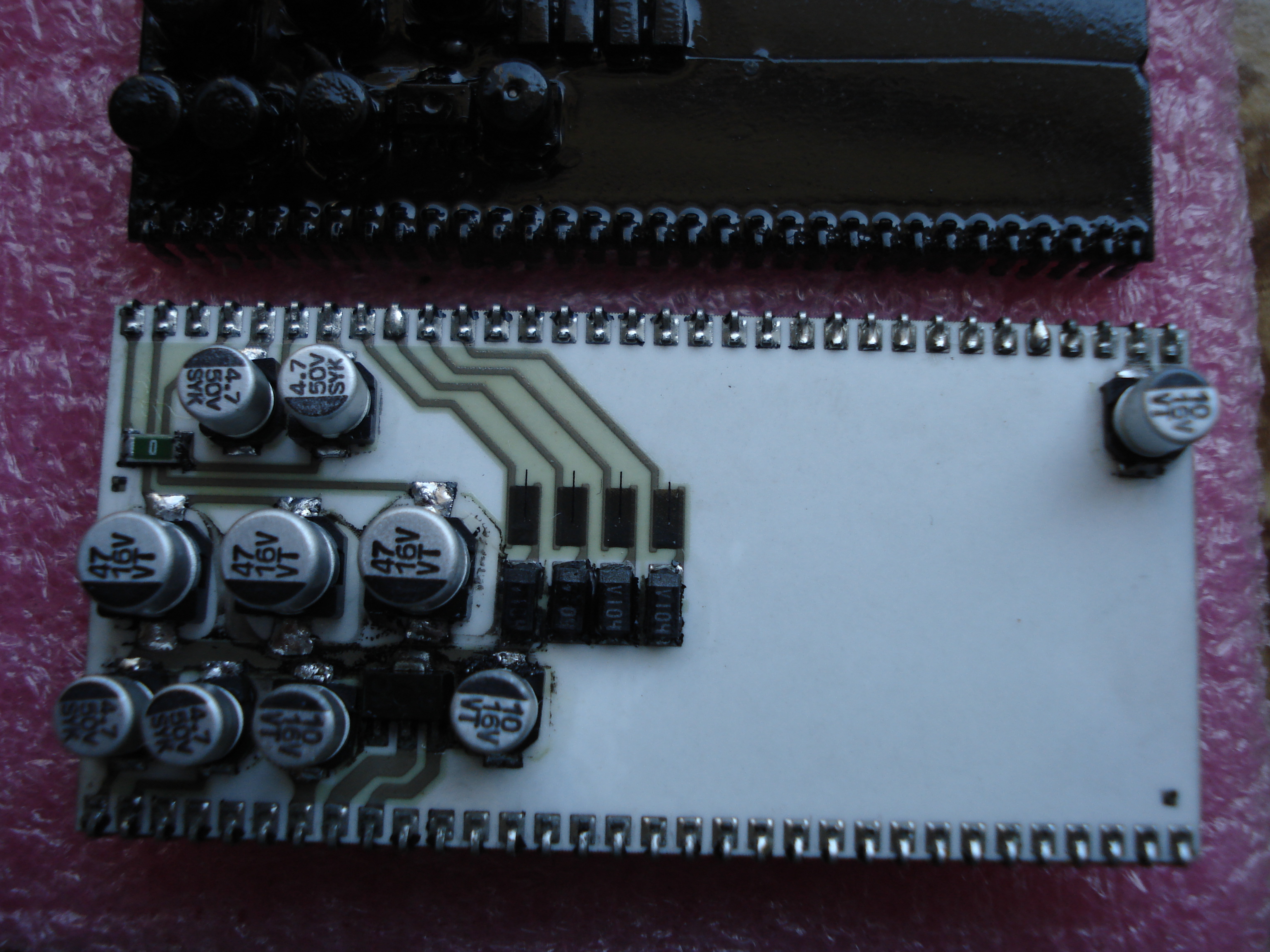
In the picture above you can see the ‘054986A’ top layer exposed.The small IC on the bottom left between the two 10uF 16V capacitors is a 78L05 voltage regulator (SOT-89 package) which powers the 4558 OP-AMP and the AD1868 DAC on the underneath of the module
Now Konami hybrid sound modules have no more secrets!Thanks again to Dragos.