Space Invaders (Taito) 3-Layer repair log #1

 PCB Repair Logs  Comments Off on Space Invaders (Taito) 3-Layer repair log #1
Dec 102015
 

I was recently given a Taito 3-Layer Space Invaders boardset by a friend to look over.  The problem was that it was not running, completely dead with a clicking sound coming from speaker (sounds like watchdog barking to me).

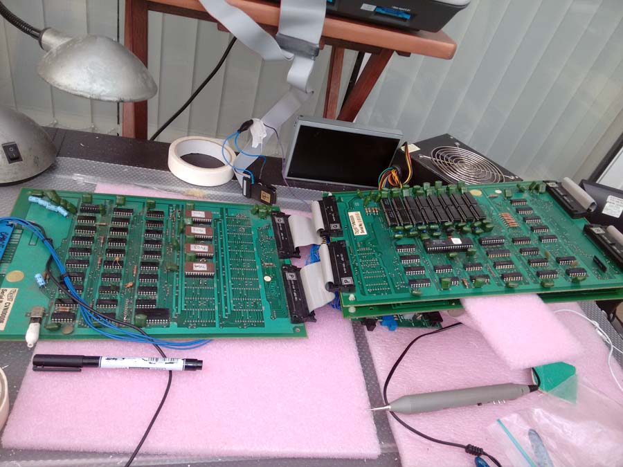
I powered up the PCB stack on the bench and checked the status of the 8080 CPU.  I could see right away from probing pin 19 (SYNC) that the clock circuit was not running.

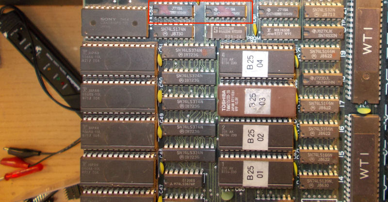
On the ROM board, I could see that the crystal was intact, so I checked the 74S04 (IC1) which I was sure was drives the clock next to the crystal.  I found that most of the pins were floating.  Replaced it and I now have a clock (note to myself, 74HC04 will not work), watchdog no longer barking but still no display.

ace_si_1

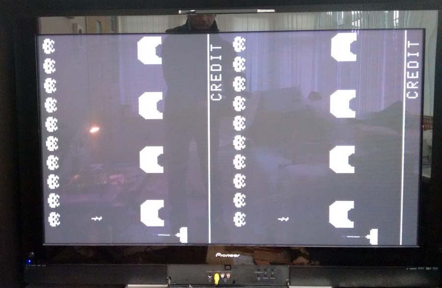
On further probing, found a bad 74161 counter at location IC6 with pins 11 to 15 stuck HI.  Replaced this and I now have a display, but it appears to be doubled up;

ace_si_3

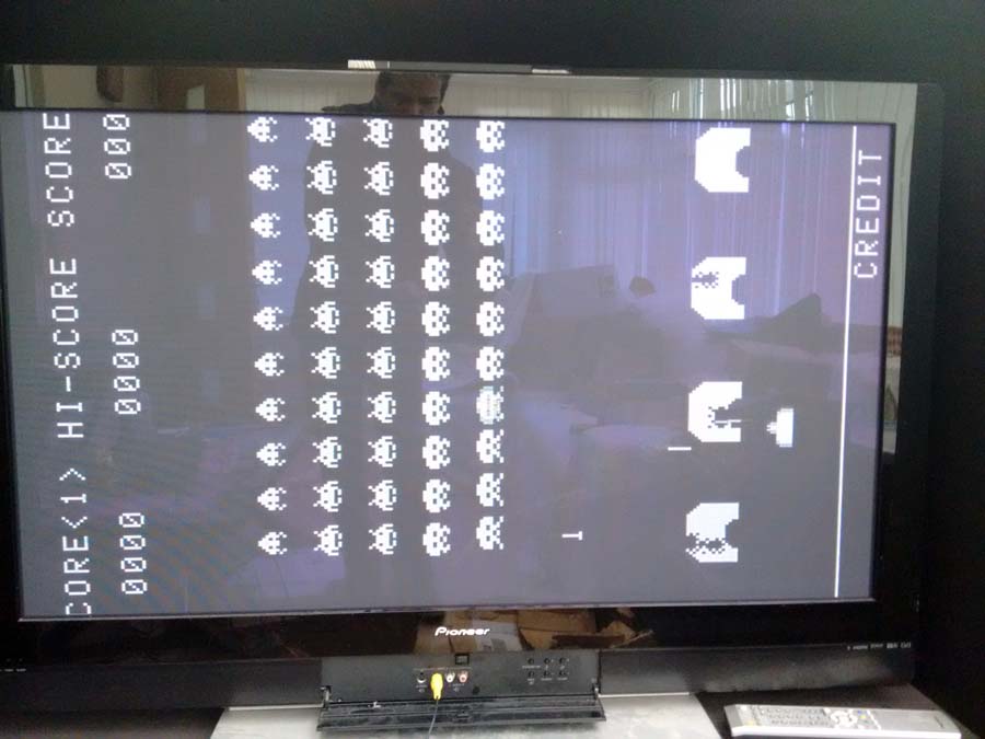
Eventually located the problem to IC28 which is a 74LS83, pins 2, 6 & 9 were stuck LO.  Replacing this restored the display;

ace_si_2

Note, I am using the composite input on my Plasma TV, as the PCB is composite only and not RGB.

Space Invaders live to invade another day!

Dec 102015
 

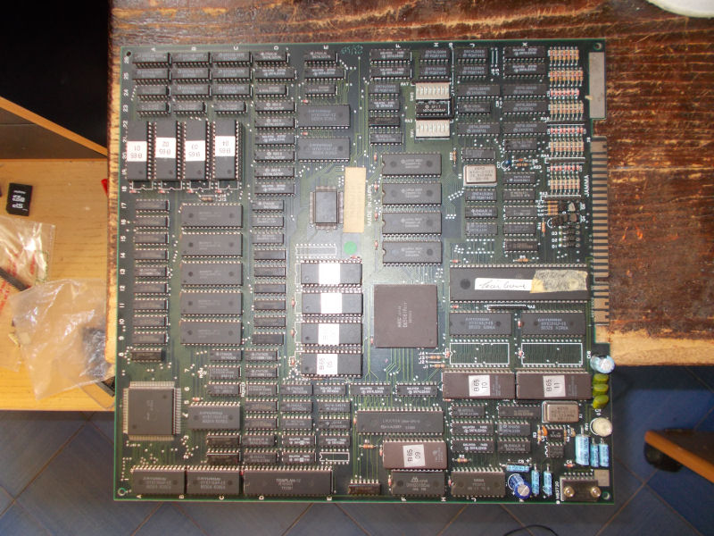
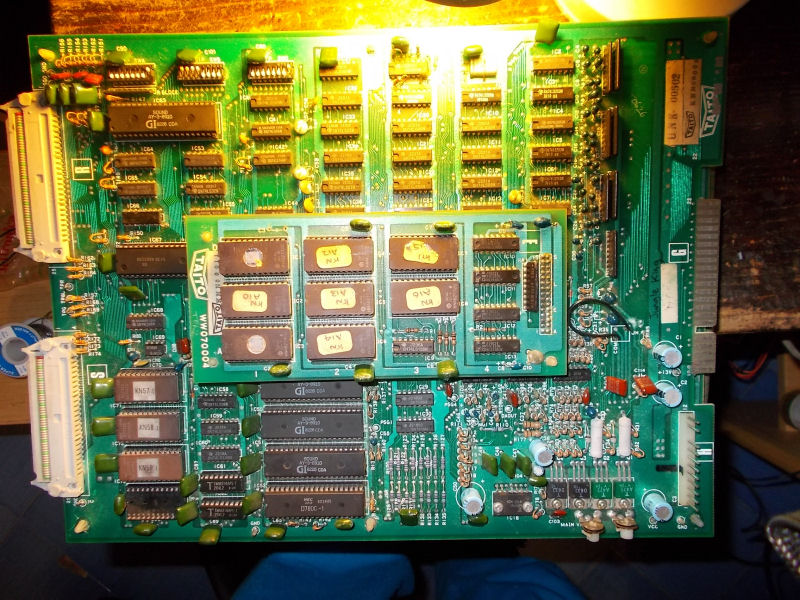
I have this Tatsujin PCB in my collection :

Tatsujin_PCB

Some days ago I wanted to play it on my Astro City so, before rotating vertically the monitor, I tested the board on a supergun.Game was running absolutely fine but I noticed some wavy lines on screen as it was some kind of interference/noise:

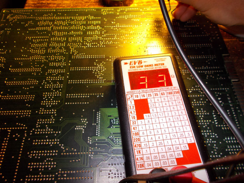
I remembered I had same issue on some boards in the past and fault was due an electrolityc capacitor with increased ESR (the role of a capacitor is to block the DC filtering the AC ).So, with my ESR meter I went to test in-circuit the electrolytic capacitors and I came across a 470uF 16V one @C1 (the one that filters the +12V for the audio amplifier) with a high ESR :

bad_470uF16V@C1

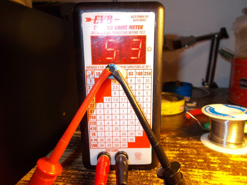
You can see from ESR chart that a typical value for a 470Uf 16V electrolytic capacitor should be 0.2 Ohm while I measured 33 Ohm.So I desoldered and measured it out-of-circuit having confirm it was really bad (53 Ohm measured):

470uF16V@C1_out_or_circuit

With a good capacitor fitted no more wavy lines and finally I could enjoy this cool shoot ’em up on my Astro City.

 Posted by at 2:24 pm
Dec 082015
 

I bought this faulty original Jungle King PCB from a JAMMA+ forums user last year but I never had time to look at :

Jungle King_PCB

The game itself is a classic, I remember I was used to play it during my childhood in arcade rooms and on home computer.So, I decided to fix it once and for all.Time to build the needed JAMMA adapter (board use a separate connector for power) and I got this scenario on first boot:

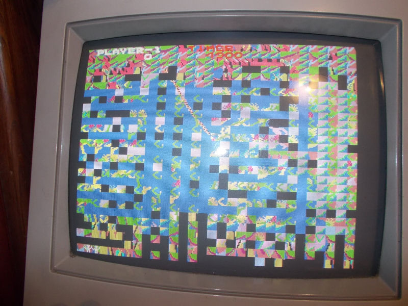
issue

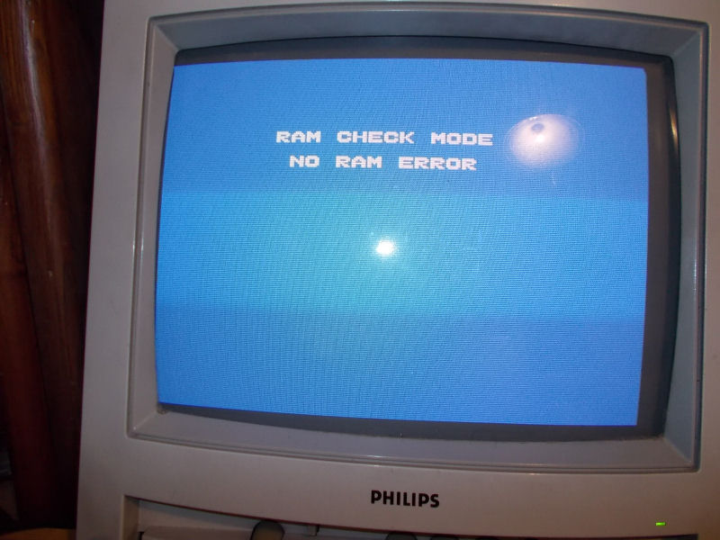
All the sprites were intact but background graphics were all messed up.The RAM test reported no problem :

RAM_test

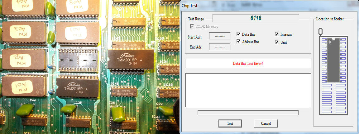
But, since all the RAMs on CPU and VIDEO board were already socketed, I want to test the chips out of circuit anyway and I found a bad 2016 @IC56 on CPU board:

TMM2016@IC56

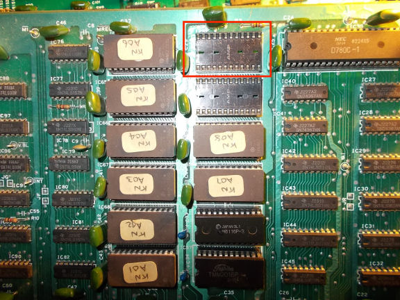
With a good RAM fitted, the graphics were perfect now but the background music was absent, I could hear only the sound FXs.After some research I found that the CPU board was missing a ROM @IC52:

missing_ROM@IC52

This ROM is, indeed, responsible of the music and only few games on same Taito SJ hardware have it so probably my board was a conversion from another game which didn’t use it (Elevator Action seem to be the common donor board).Anyway, antoher great classic preserved!


 Posted by at 11:34 pm

Wardner repair log

 PCB Repair Logs  Comments Off on Wardner repair log
Dec 062015
 

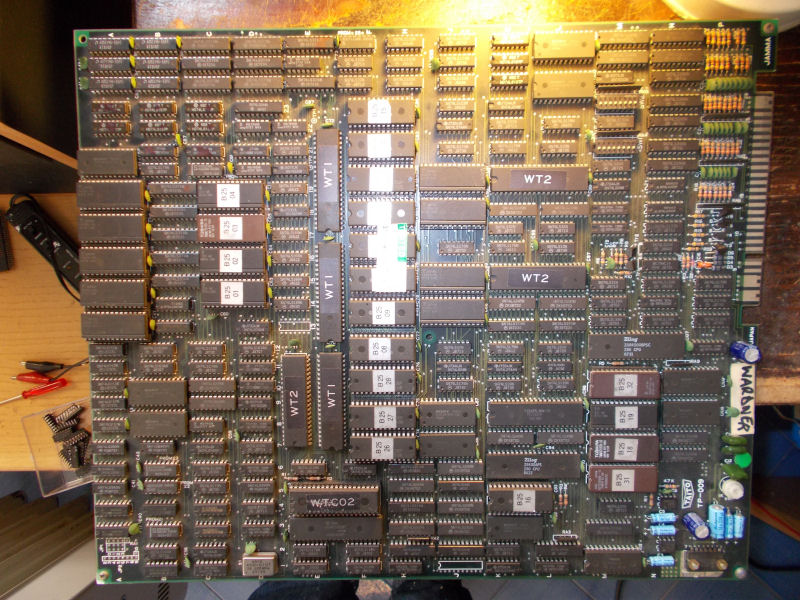
I got this Wardner PCB for a repair from my friend Zoran:

Wardner_PCB

Gameplay was fine except for some minor sprites glitch in form of some sparkling dots:

sprites_issue_

Studying a bit the hardware, I could figure out where the sprites circuitry lied:

sprite_circuitry

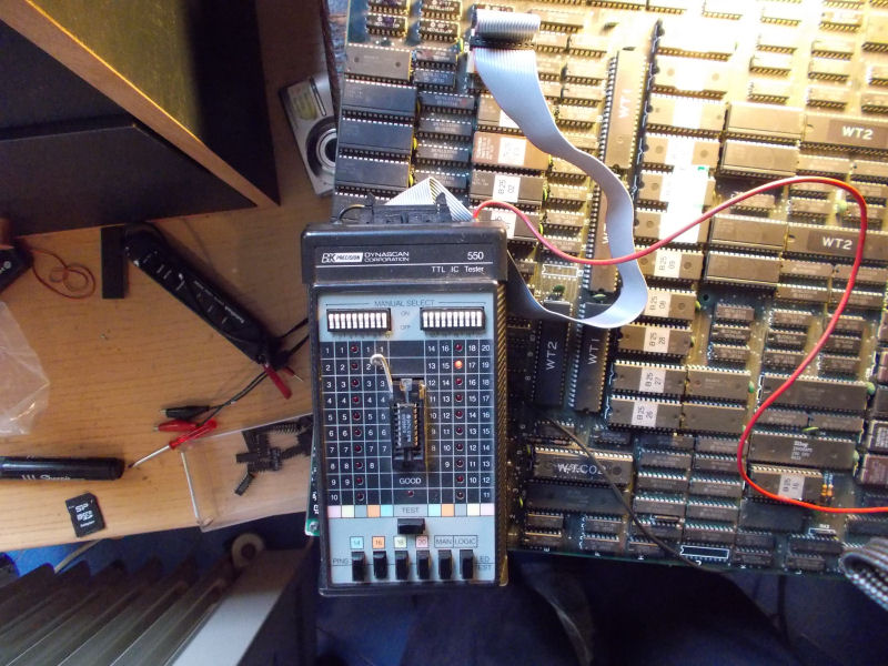
The four EPROMs were dumped good, the six 2148 RAM were fine as well.But when I probe the three 74ALS169 with my BK550 logic comparator I got trouble on pin15 of the ones @B21 an C21:

74ASL169@B21_@_faultyC21

74ASL169@B21_@C21_compare

I desoldered them but they tested fine in all my programmer.I replaced them anyway and this cleared the sprites issue.Job done.

 Posted by at 10:56 pm
Dec 042015
 

Another Rainbow Islands PCB to repair.

This, like the previous repair (#7) showed a solid white screen, however, if left alone for about 30 seconds I would get the following displayed;

IMAG0151ri

I found a bad object/sprite 2018 (6116) RAM at location IC50, so this was replaced with a fresh 2018 RAM.

The PCB was now working 100%, and put on the shelf.   That was not the end of it though.

The next day, the PCB was dead again, just showing another solid white screen.  Probing around PCB at the logic, eventually I came back to the object RAM and found that another had failed at location IC51.  This was then replaced, and the PCB sprang back to life but now with issues.  Colours were missing or wrong on the display.

You can just see from my blurry picture that the RAINBOW PROJECT screen is all wrong, no blue background and the colours are missing.  Only the first two letters on each row have a colour (green and grey);

RI_20_B

Here, interestingly, the 1UP and 2UP are white, should be green (1UP) and blue (2UP).  Also, the HIGH SCORE and TAITO logo should be red.  The Rainbow Islands logo looks intact, but the colours are solid and not rotating like they should;

RI_17_B

The MAP screen has not escaped either, most of the colours are gone;

RI_18_B

The actual game has suffered too.  It’s hard to tell, but everything is there and perfectly formed, just missing colour so either appears corrupted or simply missing;

RI_19_B

Not even the TEST CARD escaped;

RI_16_B

I have already ruled out the TC0070 RGB SIP module as being the cause as the colours are there, just not in the right places.

While I was probing around the board, things got worse, now the sprites have broken up;

RI_21_B

Eventually, the PCB stopped running again and I got this message on the display;

RI_5_B

Another failed object/sprite 2018 (6116) RAM, this time at location IC50.

RI_7_B

So this was replaced and I now got this display;

RI_4_B

At first glance I thought it was still the same message, OBJECT RAM ERROR, but then noticed this time it was COLOR RAM ERROR.

So, I replaced the bad colour 2018 (6116) RAM at location IC70 and the PCB was running again, with the sprites now intact again.

RI_6_B

At this stage, I was becoming a bit frustrated with the failing RAM, so I bit the bullet and just replaced them all so I can concentrate on the colour problem;

RI_3_B

RI_11_B

It was a good move because now at least the PCB was running stable.

I was starting to get a bit fed up looking for the colour problem, and Caius very kindly offered me some help.  Infact, he was a massive help and told me exactly where to look for the problem.

With help from Caius, eventually I found that pin 15 of the 74LS157 at IC36 was floating (using my logic probe).  This is the IC’s enable line, and it should have been tied to VCC (through the orange disc 104 capacitor).

It was then I notice the burned/damaged trace going to the orange disc 104 capacitor;

RI_2_B

Very odd place to find a damaged trace, certainly not very accessible.  I had no idea how it was damaged until Caius mentioned it has happened to him also.  Like Caius said, I must have accidently fried the trace by short-circuiting it during my in-circuit testing.

I do recall the PC PSU for my Supergun shutting down due to a short when I was probing the PCB.

So, using kynar wire I patched the damaged trace from underneath;

RI_12_B

The game’s display was now 100% restored;

RI_13_B

RI_14_B

RI_9_B

RI_15_B

Massive thanks to Caius, whom without I would not have solved this and just given up.