There has been a fair bit of discussion going on in the background recently about how is best to dump ROM’s from a PCB.
This has mainly been centered around dumping with the intent of submitting them for inclusion into MAME but this still applies if you are dumping for your own reasons too.
Obviously the first thing that you need is an EPROM programmer of some kind. The selection available is massive and not really a topic this post will delve into too much.
I myself have 3 programmers available to use.
My main workhorse is a Dataman 48pro2. Its been fantastic ever since I bought it and the support is top notch too. The downside of this programmer is the cost.
My second programmer is a cheap generic Chinese programmer. The software is not too great and the English translation isn’t all that great either but it does the job nicely when my main programmer complains about voltages being out of spec or whatever.
My last programmer is a Needham EMP-20 (actually have two of these). I was given these from a local company that was having a clear out of their old unused equipment. They are really good but their downside is they are parallel port only and the software is DOS based. Apart from that they both work well.
So how do we dump ROM’s?
At first glance we think it isn’t much more than removing an EPROM from a PCB, fitting it into the programmer socket, selecting the correct device and clicking ‘READ’ in the software.
A lot of the time this is fine but how do we do our best to know that the dump was good? What if one of those old thin crusty legs on the EPROM doesn’t make a good connection throughout the read?
The result of the read under these circumstances will be, quite simply put, a useless dump of that EPROM.
Lets look at this a bit more. Say you are dumping with the view of submitting to MAME. You dump the ROM(s), bundle it up in a zip file and send it off.
Then one of the developers takes the time to add it to the source code and do some testing. Now lets say the game doesn’t work or some of the graphics are messed up.
In some circumstances, say for instance the game was a prototype or something, that developer or developers starts looking for errors either in ROM dumps or the emulation itself. Before you know it he/she has invested a few hours of their time.
The other scenario. You dump the EPROM for your own purposes. Some days, weeks, months or years down the line you need to program yourself a new EPROM because the old one has died or suffered from bitrot. You program it up and fit it but it doesn’t work. Is there something else wrong with your PCB? But what if you just didn’t dump it correctly in the first place and you never realised. You never made the dump public so any potential testers out there couldn’t even do the testing on your behalf and notify you. Congratulations, you’ve now got a useless piece of electronics on your hands.
Either way your dump was bad but we could have potentially avoided this whole mess by carrying out some really easy checks. Lets look at it.
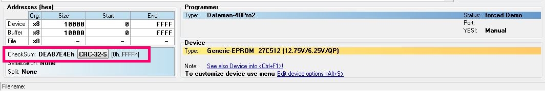
When dumping a ROM we want to be extra sure that every time we read the device we get the same data. Every programmer I’ve ever used will display a checksum of the data dumped (although YMMV) like this.

If you read the device a second time and the checksum is different from the first time then we clearly have an issue but what if it’s the same every time? The data could still be bad so let’s try physically removing the device from the programmer and reinserting it then trying to read it again. Is the checksum still the same? If not then we are probably going to need to investigate further. If they are the same then how about we remove and reseat one more time just to be sure. This may sound like a waste of time but the reality of it is it only takes a few seconds for older EPROM’s to be read out and it could potentially save everyone a lot headache further down the line.
So now we have dumped the ROM (three times) and we are happy that no matter what we do or how we position it in our programmers we get the same dump each and every time. What next?
In the case of an arcade PCB let see if the dump we have compares to anything already dumped and included in MAME.
For this you will need the latest version of MAME available from MAMEDEV
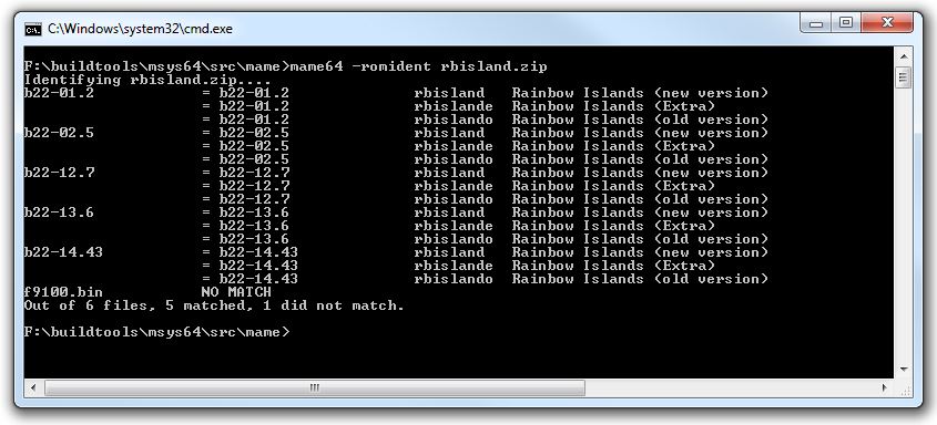
Open a command prompt at the directory where you unzipped/installed MAME and type ‘mame -romident [YOUR-ZIPPED-FILES-LOCATION]’. If you use the 64bit version then type ‘mame64 -romident [YOUR-ZIPPED-FILES-LOCATION]’ instead.
Here is an example using the rbisland romset. I’ve added a random binary file to show what happens when an undumped file is found.

What this shows is each individual file within the .zip file and the filename associated with each other romset.
The “9100.bin” file is the undumped file and you can see it shows “NO MATCH”. This means that the file is unknown to MAME.
If they are all matched then nothing more needs to be done. If they aren’t a match though then we could be looking at something undumped OR we could still be looking at a bad dump.
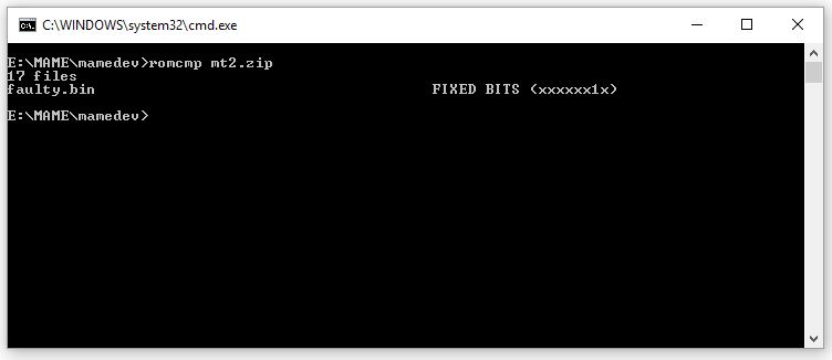
Included in the MAME package is a tool called ‘ROMCMP.EXE’. This is another command line utility that performs a variety of checks on your files. For example it will tell you if the dump is all 0xFF bytes or if the top and bottom half of the dump are the same. It can also be used to compare your files against the files currently in MAME to see how much of the data matches.
To use this tool we need our file or files in a .ZIP file.
For this example I( have used the Major Title 2 romset ZIP file and have added an extra binary file which I hand made but made bit 1 (second bit) stuck on using a hex editor.

The output is simple enough to see. It shows that bit 1 is always ‘1’.
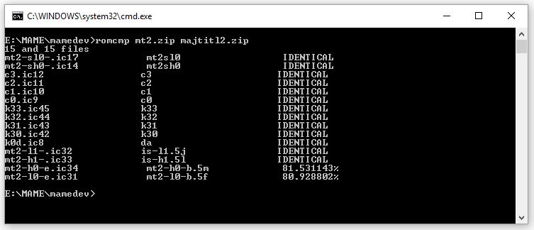
If you have dumped what you believe is a new ROM set then you can use ROMCMP to compare against an existing set.
Here I used two different sets of Major Title 2 to demonstrate.

You can see most files are identical but there are two that aren’t quite the same (these two are the main program ROM’s for Major Title 2). You can also see that they are both over 80% the same as each other. This is a good sign for a different revision of the same game especially as we have already done the previous checks on the ROM’s to confirm their validity as much as possible.
There may be other steps that people like to do on their ROM dumps but the above will give people, whether its yourself or an emulator developer trying to support it, a fighting chance.