Jul 242015
 

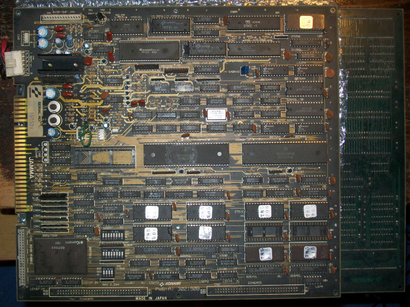
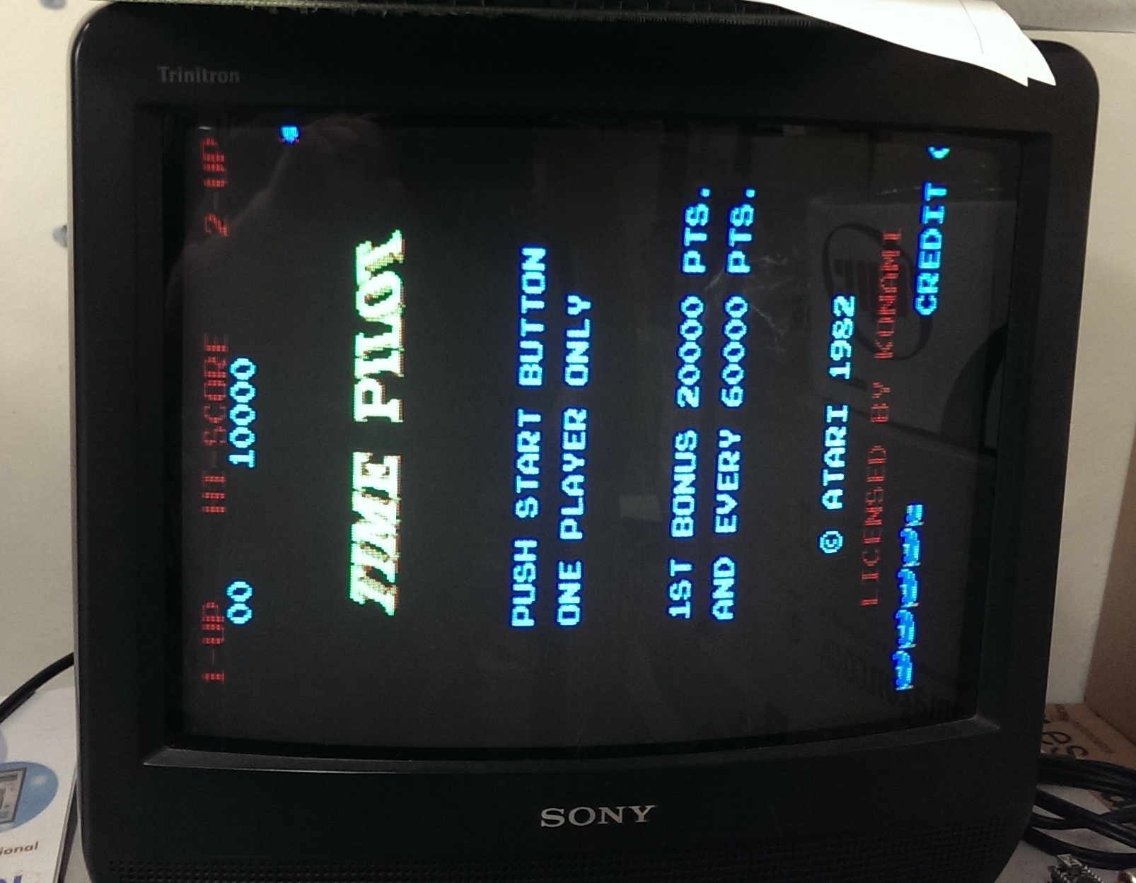
Got Muddymusic’s Time Pilot on the bench this time.
This game gave me the run around for a lot longer than I anticipated due to reasons I don’t really understand. Maybe someone can help me understand why.

So the game was meant to have two faults. The first was the RIGHT control didnt work. The second was the sound did not work.
Straight away I ran into problems. I could not get this board to sync with any of the 3 screens I have on my test rig, it also wouldnt sync properly in my Astro City cab.
I have recently bought a couple of those mini cabs and one was stripped out at the time so I used the monitor from that and the board seemed to sync up just fine.
IMAG1396

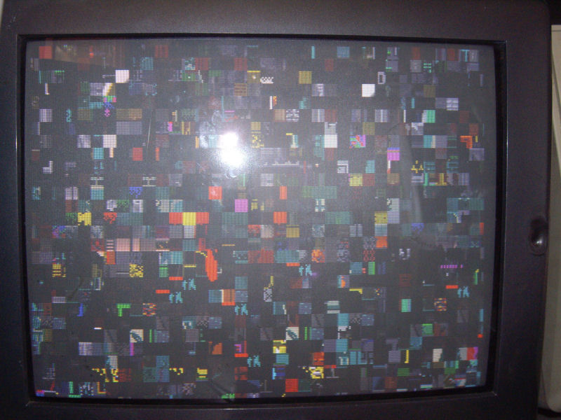
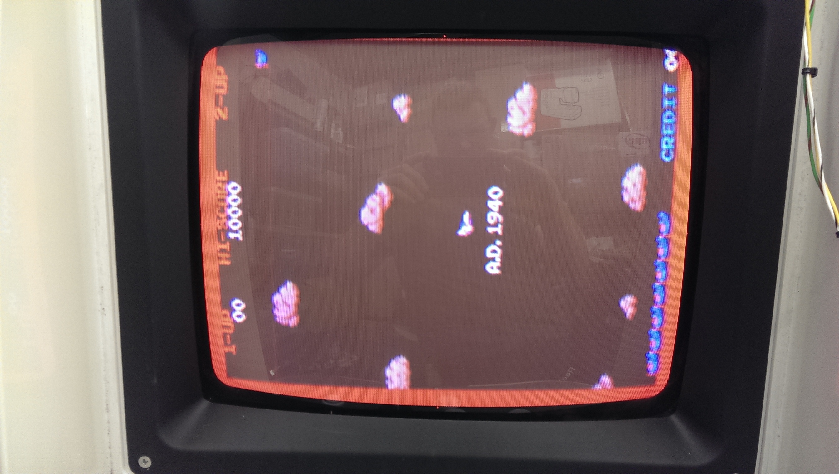
There was that big red border around but I recall having the same thing on a Circus Charlie board I fixed so thought nothing of it.
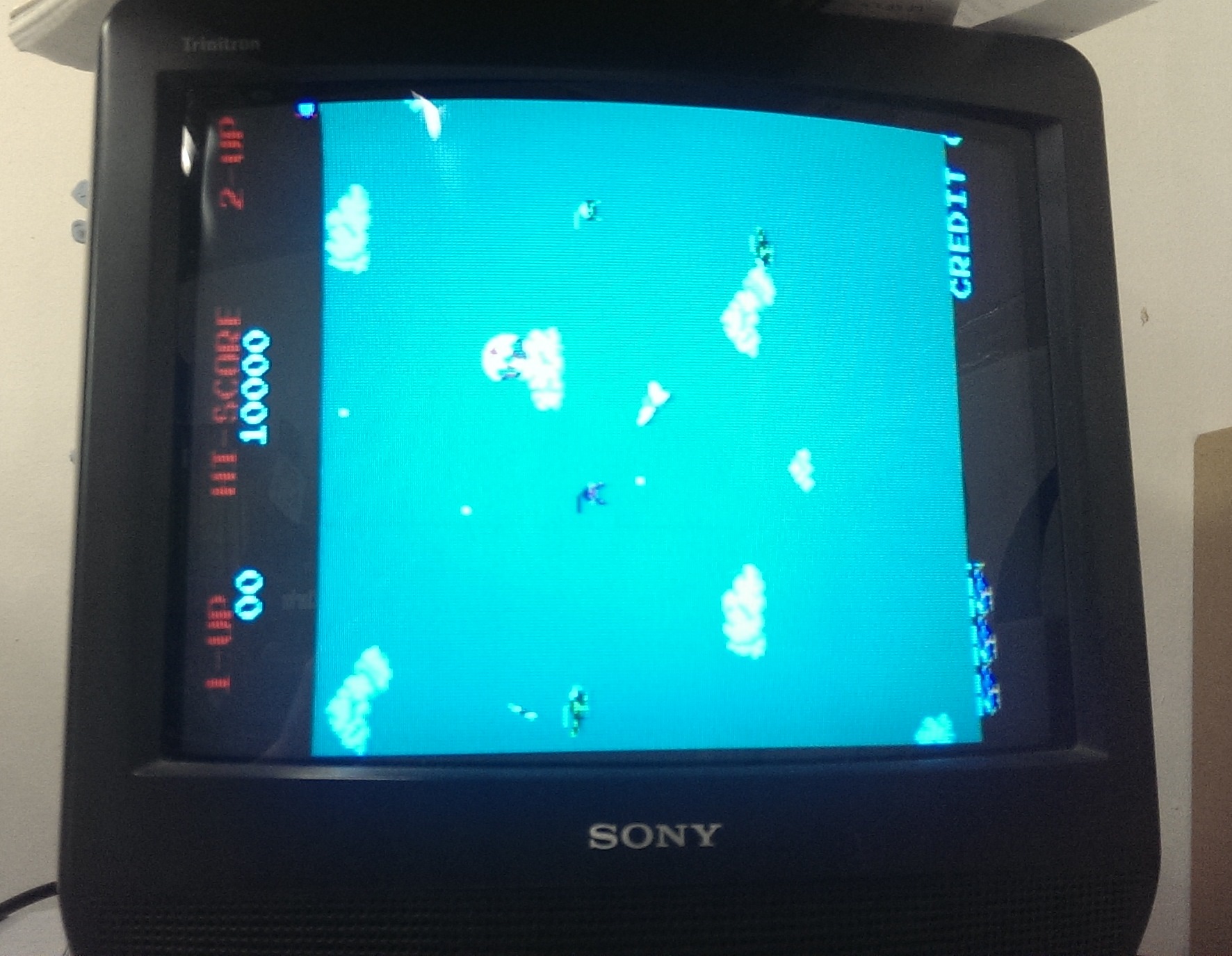
Playing the game led me to think the background colours were missing.
IMAG1399

I spent about 3 days going right through the schematics and running tests with the Fluke 9010 to figure out what was wrong. I couldn’t understand it. Muddy claimed that the background colours were present before he sent it off.

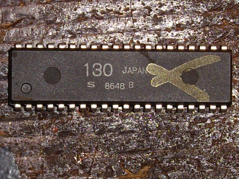
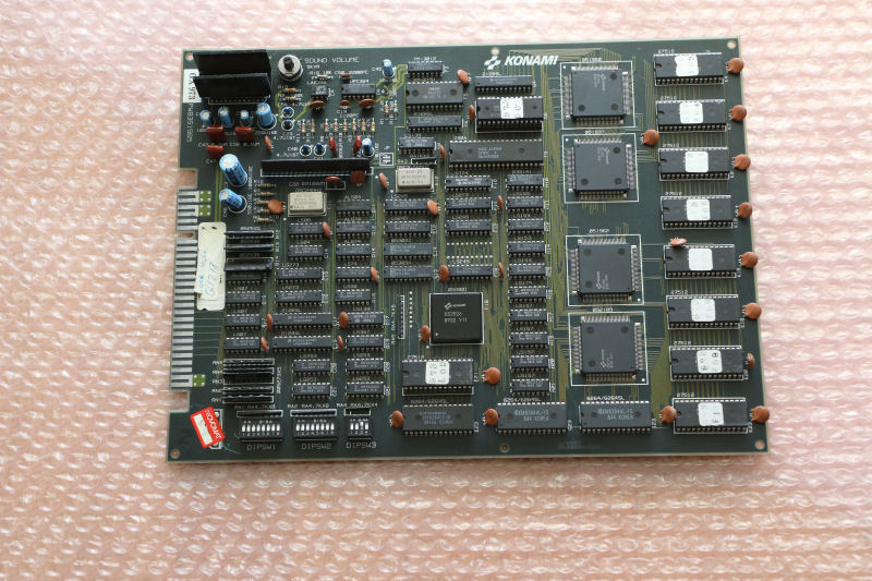
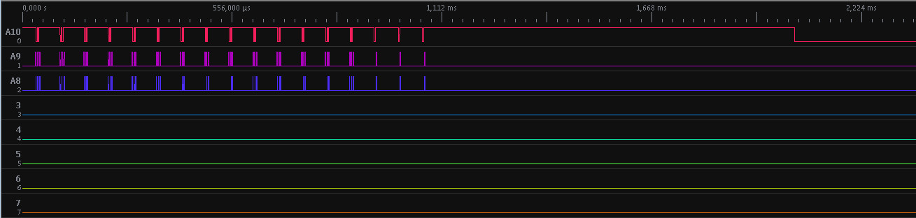
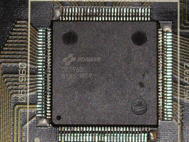
As I started doing more and more testing I started to get new faults with the sprites. I needed to figure out which chips were the sprite RAM’s so I reversed the ‘custom’ chip known as K526. In reality this chip is an 82s153. I dumped the chip and reversed it into equations

Pin 1 = MREQ
Pin 2 = RFSH
Pin 3 = A15
Pin 4 = A14
Pin 5 = A13
Pin 6 = A12
Pin 7 = A10
Pin 8 = F4

0xb400 (spriteram2)
/o12 = /MREQ & RFSH & A15 & /A14 & A13 & A12 & A10 & /F4

0xb000 (spriteram1)
/o13 = /MREQ & RFSH & A15 & /A14 & A13 & A12 & /A10 & /F4

0xa000 (main ram. covers color ram and video ram too)
/o14 = /MREQ & RFSH & A15 & /A14 & A13 & /A12 & /F4

0x8000 (Goes to pin 12 of 501 custom and also F3.)
/o15 = /MREQ & RFSH & A15

0x6000 (enable for unpopulated ROM socket, H5)
/o16 = /MREQ & RFSH & /A15 & A14 & A13

0x4000 (ROM H4)
/o17 = /MREQ & RFSH & /A15 & A14 & /A13

0x2000 (ROM H3)
/o18 = /MREQ & RFSH & /A15 & /A14 & A13

0x0 (ROM H2)
/o19 = /MREQ & RFSH & /A15 & /A14 & /A13

I figured out that the 4 x 2114 chips at D7 – D9 were the sprite RAM. 3 out of 4 had failed one by one so I ordered some up and replaced them when I got them.
All the sprites were back but still no background colours.
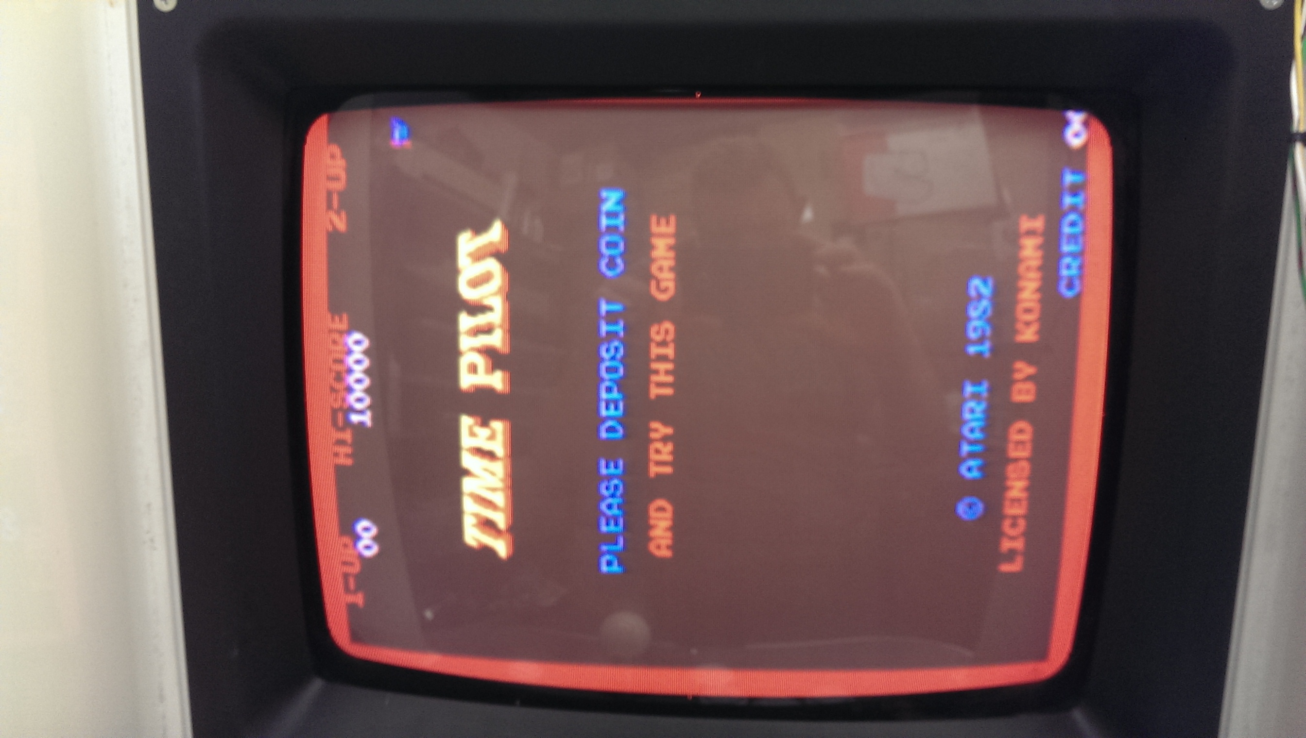
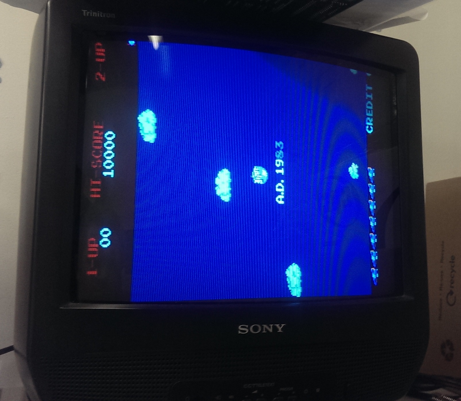
In a desperate attempt I wired the RGB-S straight into a scart connector to try a different TV. This is what I got.
IMAG1417

The backgrounds were there all along but for some reason my other monitor wouldnt display them. I know the monitor works fine with my other games but why I did this I have no idea. If anyone knows or has any theories I would love to hear why.

On with the repair.
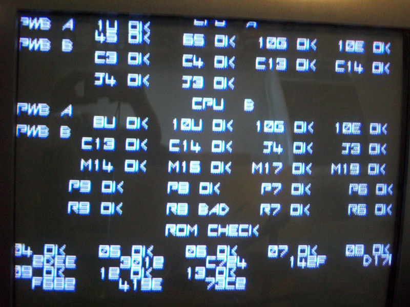
As you may already know this board gave me the opportunity to test Shoestring’s diagnostic ROM. After a few teething problems we got it working and I was able to test the player inputs. To my surprise they all worked fine and testing in game confirmed this. No idea why it didnt work for Muddy but it works now.
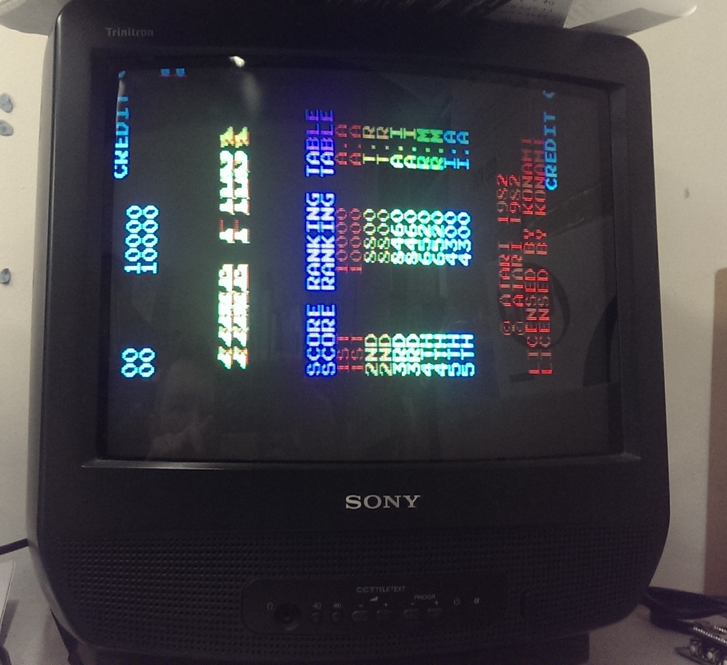
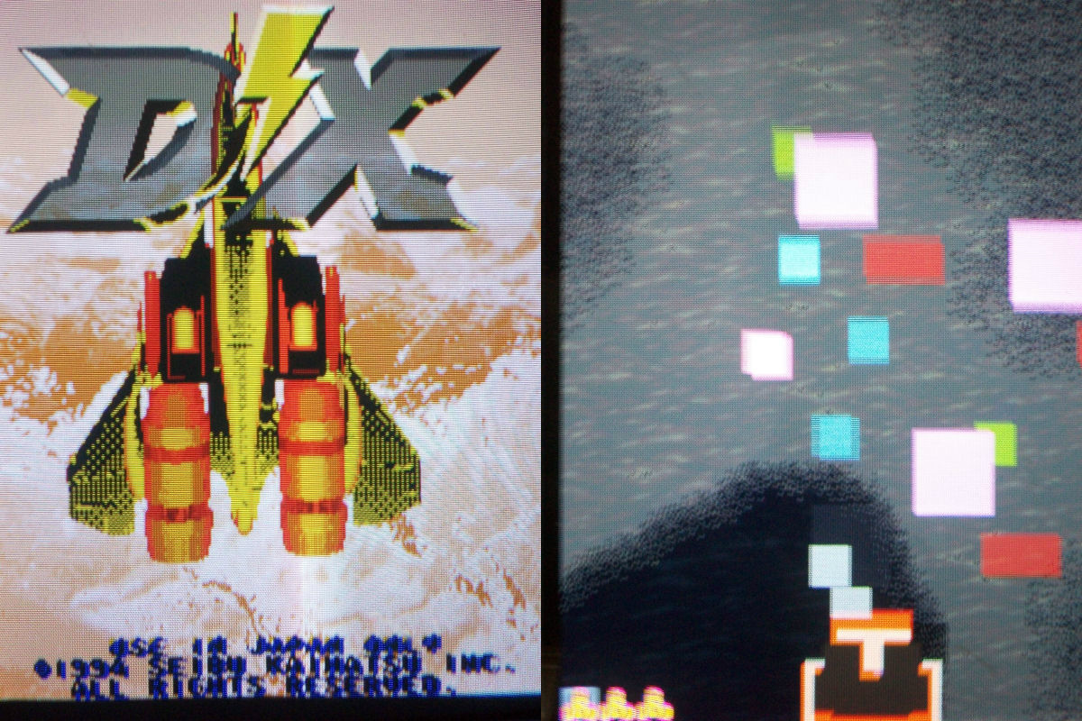
After getting the game up and running with background I noticed the main ship sprite was no longer a ship (see picture above).
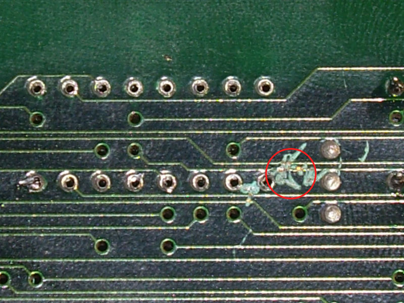
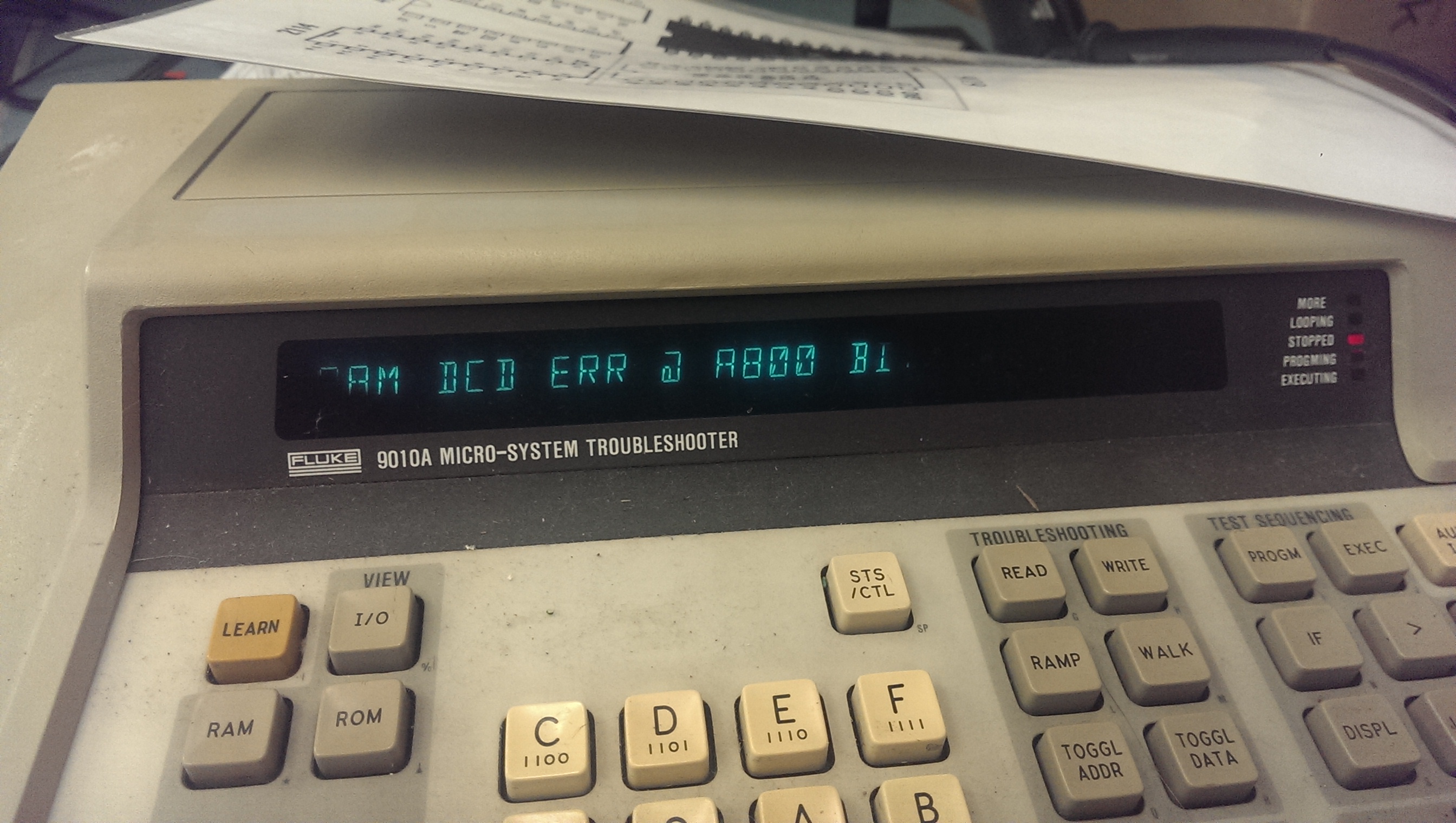
Lightly flexing the boards fixed the problem but then the board stopped working. The Fluke was already plugged in and running test gave me a DCD error.
IMAG1418

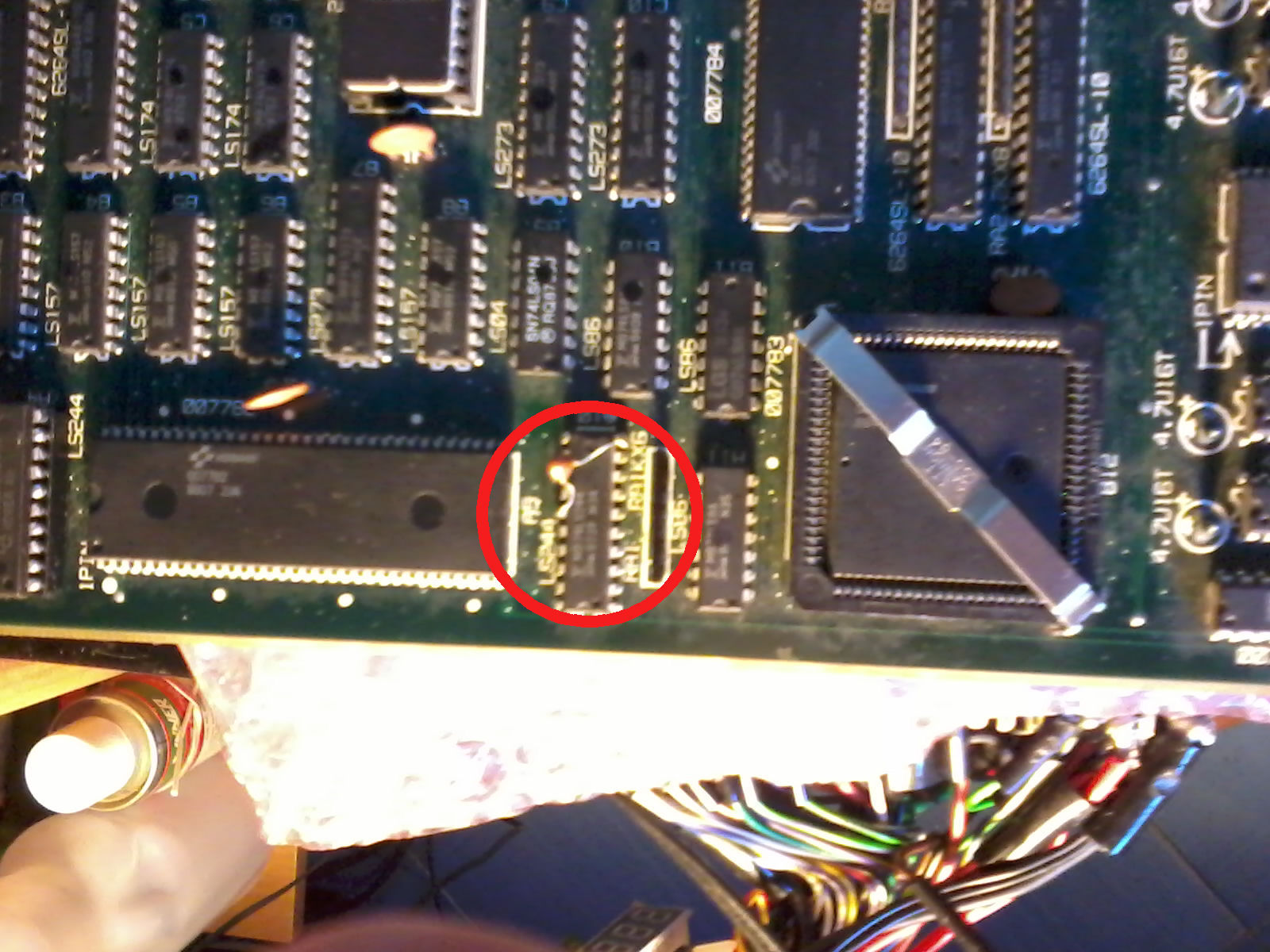
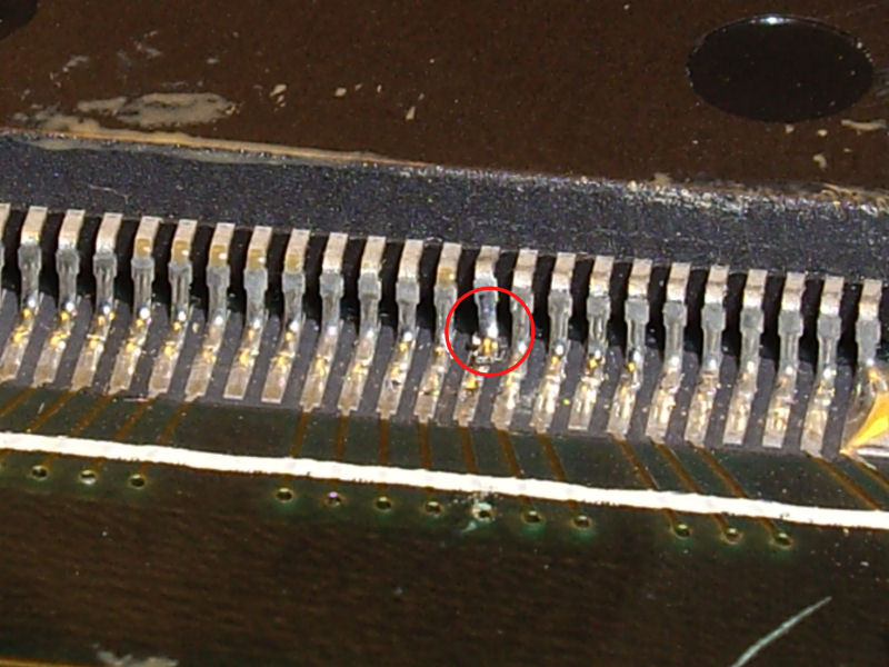
This error means there was a problem with the RAM addressing/decoding. This issue is normally missed by POST routines as they simply write a value to an address and read it back comparing it. The Fluke doesnt do this. It writes specific values to specific addresses so if there are any addressing issues it can tell. My issue ended up being caused by me. There was a tiny flake of loose solder bridging two address lines on the main RAM. Removing this made the game boot again but now I had another issue.
IMAG1423

The graphics were now doubled up.
This was easy to find and ended up being a dodgy socket on the 082 custom chip at location F5. I replaced the socket and now everything was good again.

With that all done it was on to the sound.
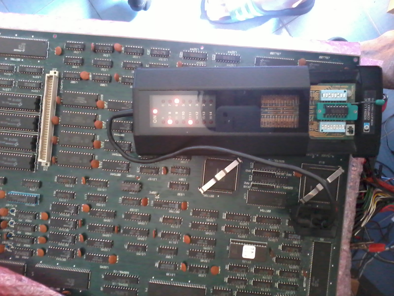
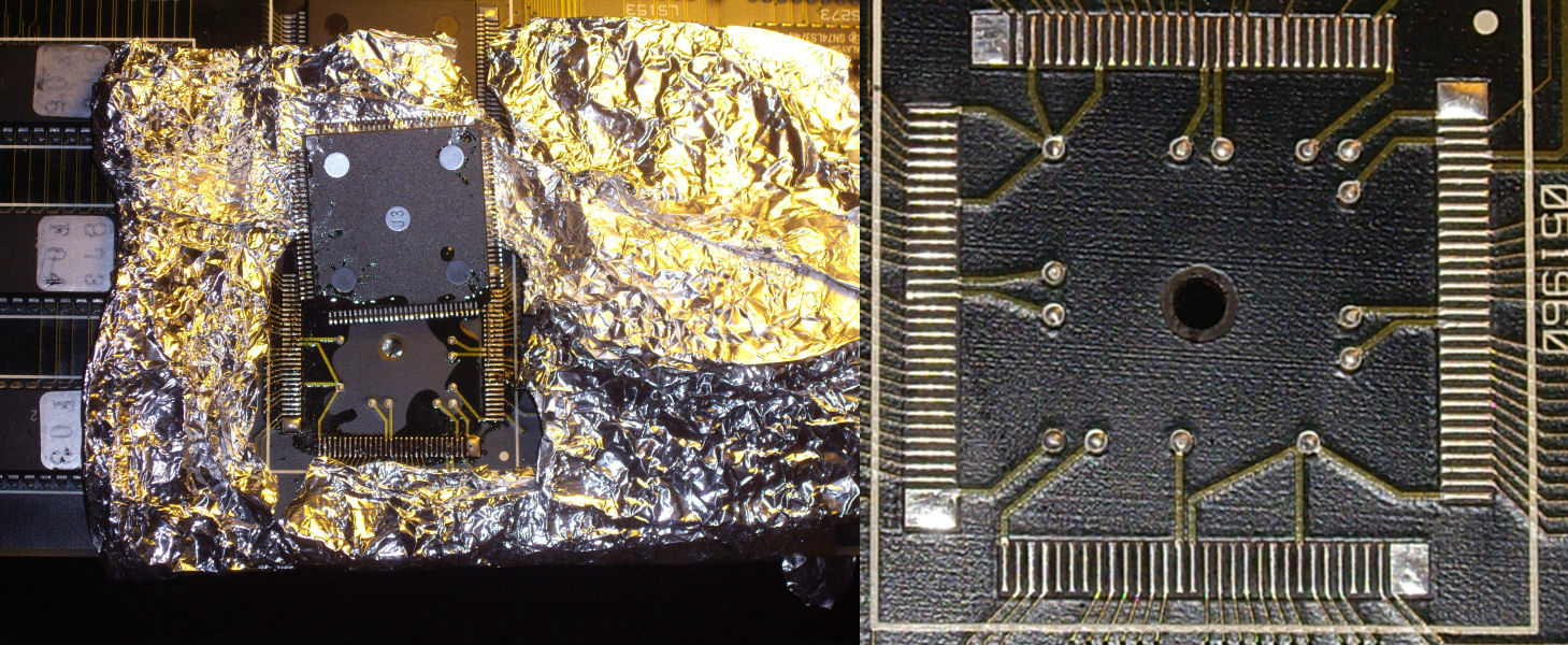
I was getting a little tired of looking at this board so after a few preliminary checks I just desoldered the Z80 and fitted the Fluke.
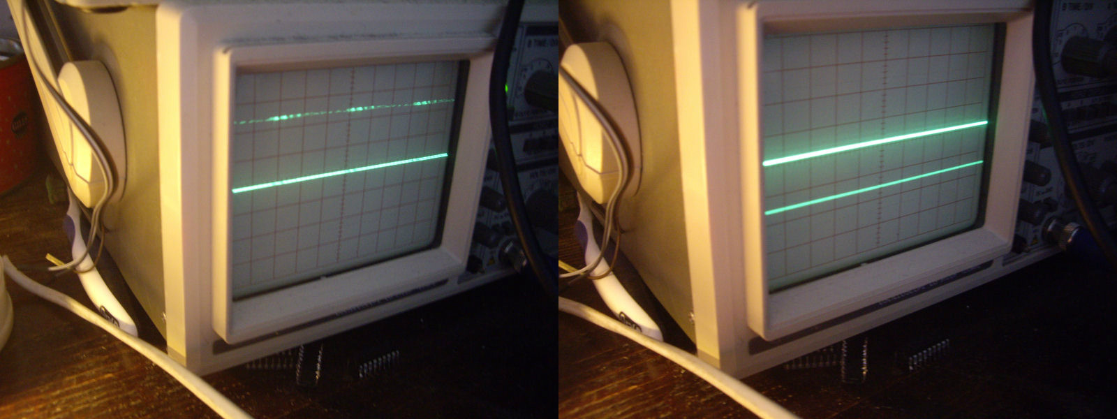
BUS CHECK showed bit 0 and bit 1 were stuck LOW. I wrote 0x55 to a point in RAM and read it back, I got 0x50.
I then wrote 0xAA to the same point and read it back, I got 0xA0.
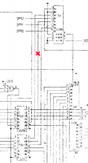
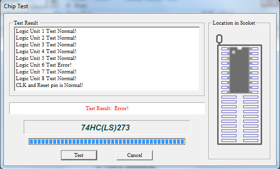
Looking at the schematics I pinpointed the offending RAM chip to the 2114 at B7.
Replacing this game me back the sound.

On the final test the sprites died again!!
I replaced the last 2114 RAM chip on the main board and this is now 100%
IMAG1429

IMAG1426

 Posted by at 9:14 pm

Block Hole repair log

 PCB Repair Logs, Repair Logs  Comments Off on Block Hole repair log
Jul 142015
 

Got this Konami Block Hole (export version of Quarth) from my friend ‘mastercello’ :

Block_Hole_PCB

Board was marked with “sprite issue” and indeed it’s what I got once fired it up:

sprites_issue

Some sprites (like main ship, see the above picture) were garbled and totally wrong.There are eight 27256 EPROMs containing all the sprites so I went to probe them with a logic probe and I found that the common address line A10 (PIN21) of four of them was not prperly toggling compared to the healthy lines A9 and A8 for example.This was confirmed also by my logic analyzer:

A10_address_lines_analysing

I was able to trace this faulty address line back to the sprites generator ASIC marked ‘051960’:

051960_ASIC

So my suspects was that this ASIC would address the four sprite ROMS wrongly due its weakened address line.To confirm this I lifted the involved pin:

051960_lifted_pin

and its behaviour was the same as before when connected to sprite ROMs (on the left the an healthy address line, on the right the faulty A10)  :

address_lines_comparing

At this point, I was pretty sure the ASIC ‘051960’ was faulty in this address line so I played the card of replacing it:

051960_replacing__

And I was right, this restored graphics completely.Board 100% fixed.

fixed

 Posted by at 10:16 pm

Raiden DX repair log

 PCB Repair Logs, Repair Logs  Comments Off on Raiden DX repair log
Jul 102015
 

Another board from my friend ‘mastercello’ and another quick fix.

We have on the bench a Raiden DX (Seibu Kaihatsu) PCB in  good shape:

Raiden DX_PCB

Board booted but colors were wrong and sprites colored blocks:

issue

This Seibu hardware doesn’t use many components since most of logic has been condensed in some custom ASICs which have mostly graphics functions so I focused on them.Like I usually did I probed the tightness of each pin with a small needle and found some lifted pins of the one stamped  ‘SEI252 SB05-106’ (QFP208 package).

SEI252

A simple reflow did the trick and fixed graphics completely.

fixed


 Posted by at 10:47 pm

Out Zone repair log #1

 PCB Repair Logs, Repair Logs  Comments Off on Out Zone repair log #1
Jul 102015
 

This repair log is proof that we must always start from the simpliest things!

Another faulty board from my friend ‘mastercello’, this time an original Toaplan Out Zone :

Out Zone_PCB

He told me that it worked once and then nothing.Actually when I first powered it up I got this :

The screen with the wavy lines is common on all the Toaplan PCBs which run on similar hardware.It means that the system is being intialized but it should last until the CPU starts to properly execute code.In my case this screen was permanent so there had to be a problem in the main code execution.First thing I did was to check CLOCK, /RESET and /HALT lines of 68000 main CPU, they were fine.Then I dumped the two 27C010 programs ROMs and got from my programmer a warning about a poor contact on pin 17 (which is a DATA output) of the one labeled ‘TP018_08’:

poor_contact_PIN17

A closer inspection of the device revealed many oxidixed pins.A bit of fine sandpapering is what the EPROM device needed and enough to fix the board completely.

fixed

 Posted by at 1:48 pm

Donpachi repair log #1

 PCB Repair Logs, Repair Logs  Comments Off on Donpachi repair log #1
Jul 102015
 

My friend ‘mastercello’ sent me this Donpachi PCB for a repair:

Donpachi_PCB

The board was in good shape but had a GFX issue where background layer was partially missing with lines across it:

layer_issue_

Studying the hardware and with help of MAME I could identify the devices containing the data of the two background layers, they are two 42PIN 8 Mbit MASK ROM @U54 and U57.Probing them with a logic probe I found that the one @U54 has all its data lines stuck LOW or HIGH, also the two control lines /CE and /OE were stuck LOW though they were properly connected to a near ASIC which generates these signals.Obviously this was totally abnormal.As confirmation of my theory I was able to reproduce ths issue in MAME using a dummy ROM file of the background layer data instead of a good one:

MAME_reproduced_issue_

This was enough to convince me to desolder the MASK ROM and read it in my programmer resulting in an empty dump.Direct replacement for this 8 Mbit 42PIN MASK ROM is a 27C800 EPROM though the silkscreening under the chip sais ’23C16000′:Fitted a freshly programmed device restored graphics completely.

U54_replacement

fixed


 Posted by at 8:35 am