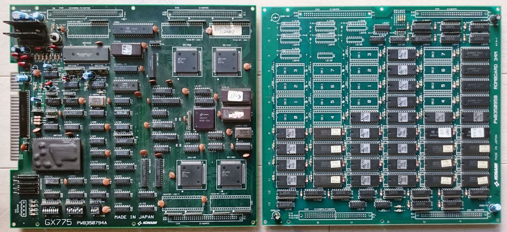
I bought a dead Rastan PCB for a fair price on a forum.
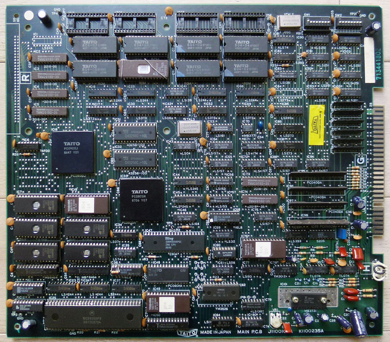
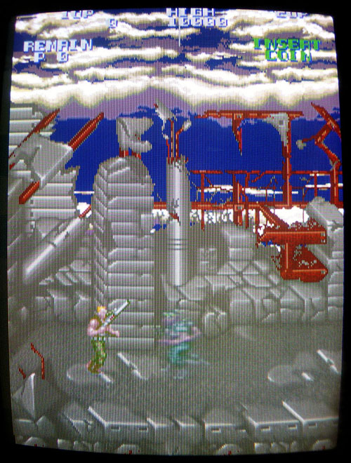
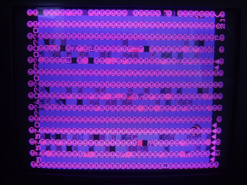
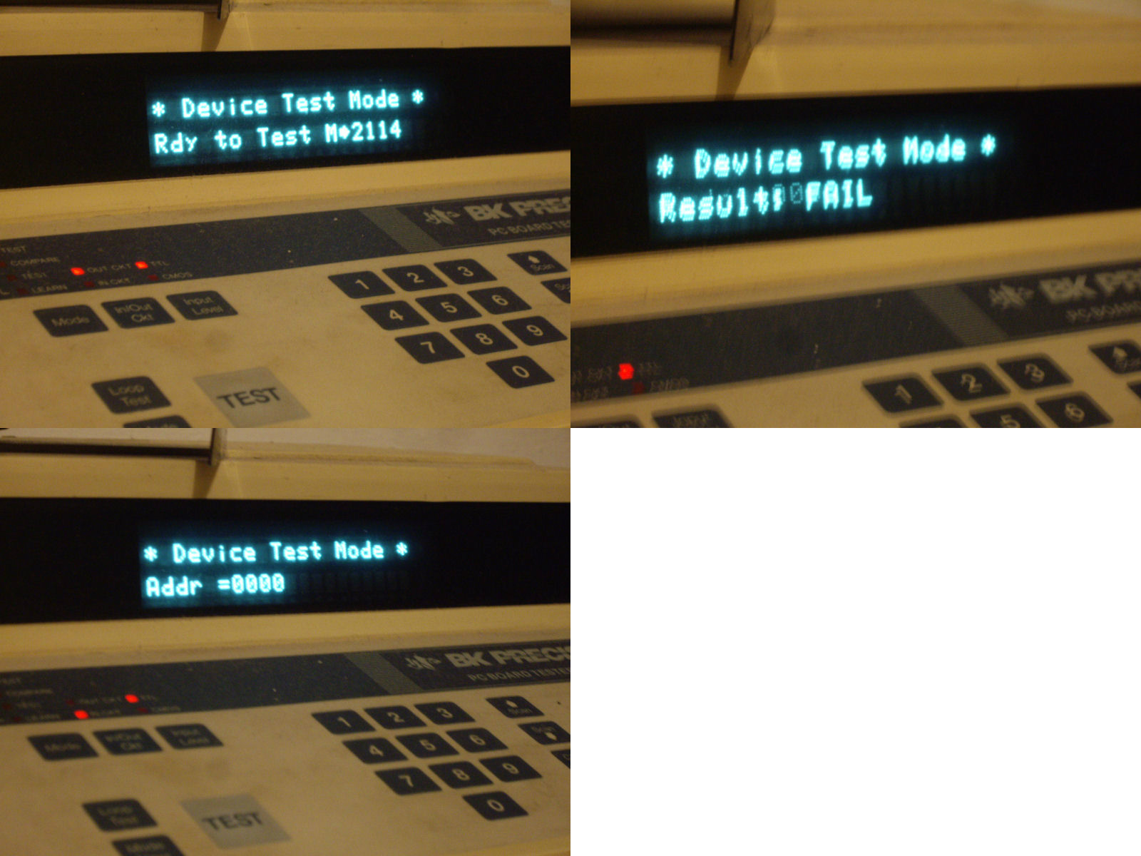
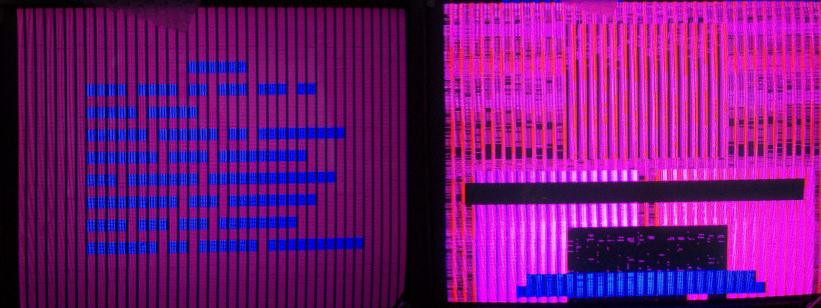
All I got was a screen with garbled graphics on boot:

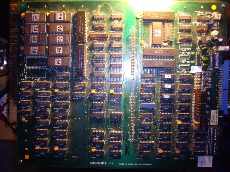
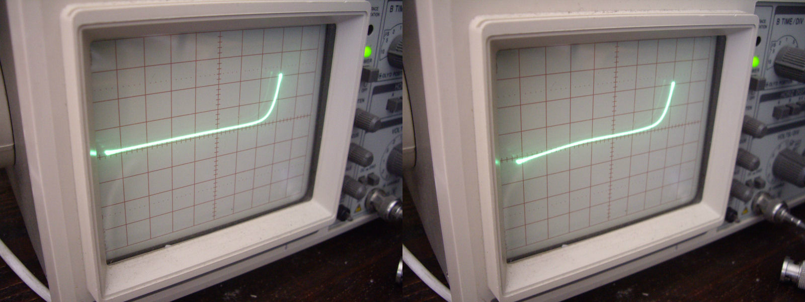
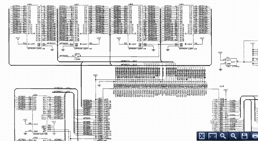
Luckily, schematics are available online for this board. Anyway, I spent hours with my scope trying to find why there was no activity at all in the CPU area. I desoldered the two RAMs and the 68000 (all were tested OK as well as the ROMs).
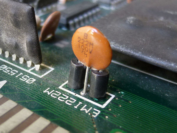
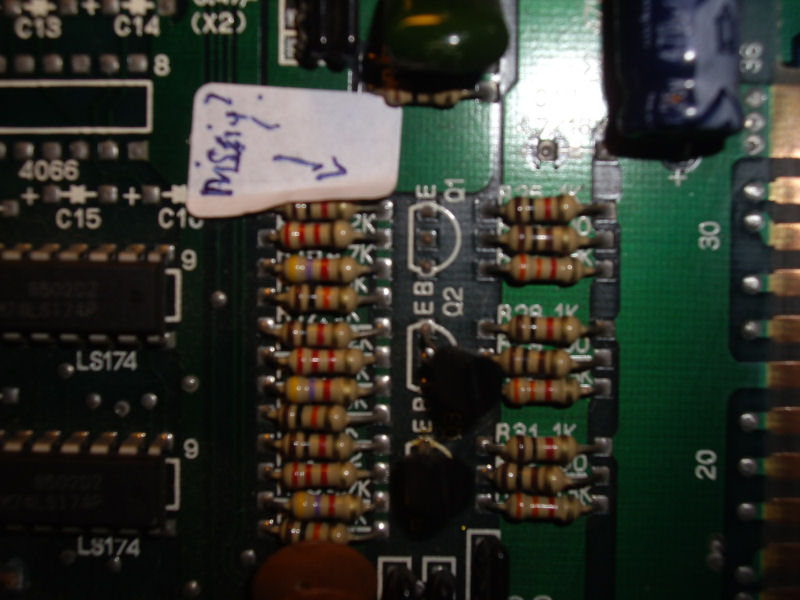
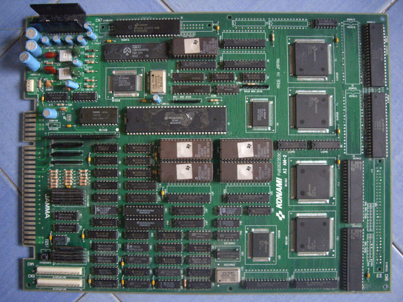
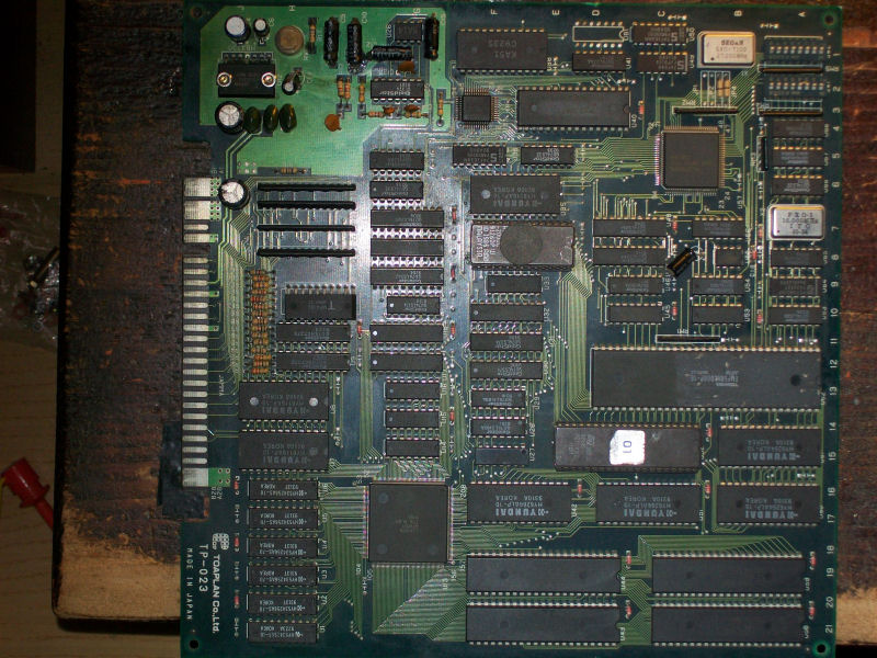
Next, I desoldered the 2 PALs that are involved in the address decoding (labeled B04-09 @ IC11 and B04-10 @ IC12) in order to check them and finally discovered that B04-10 was slightly cracked (it is the one at the bottom-left corner of the board, you could figure it was heavily bended there) and, with no surprise, it couldn’t be read on my programmer. See the crack in the middle of the chip, it was unnoticeable before removal:
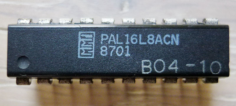
Fortunately, PALs for this game are available on JAMMArcade.net so I took a blank GAL and burned the equivalent file but then got a black screen… Ok, that was my fault as the file was an untested dump from a PAL16L8 and needed to be converted to GAL16V8 in order to work properly. I did the conversion with PALTOGAL.EXE, reburned it then the game booted !
Great… But my enthusiasm quickly stopped as I noticed some issues:
1) The game sometimes crashed then rebooted, it happened 1/3 times when I started a game.
2) There was no sound (I could sometimes randomly hear a voice looping then fading away).
3) A few sprites were garbled.
It turned out that both issues 1) and 2) were related to a defective sound RAM chip @ IC50.
System11 reports the exact same problem on one of his Rastan repair logs (corrupted sound with main CPU crashing randomly due to a defective sound RAM).
This was not easy to troubleshoot because that RAM @ IC50 had seemingly “normal” pulsing signals on every pins and piggybacking didn’t worked at first. After reading that repair log from System11, I tried again piggybacking and that time it worked ! (well, it partially worked and not all the time)
So I’ve replaced the chip and got it working fine with sound and no freezes !
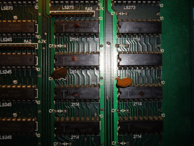
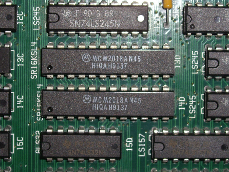
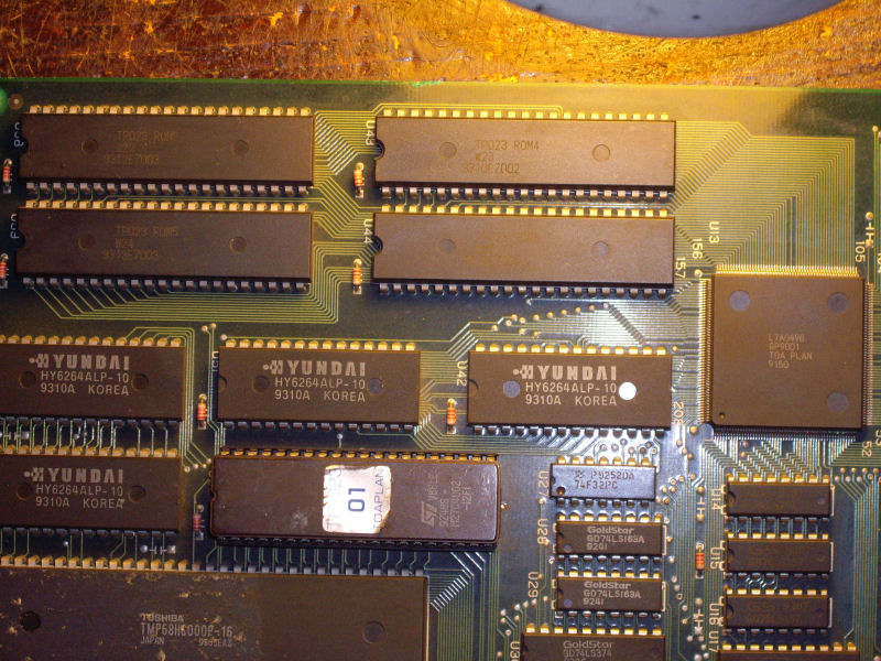
Only the issue 3) was remaining. The fault was most probably due to one of the gfx mask ROMs @ IC28 (1Mbit into a 28pins chip) that was replaced by an hacked 27C010 1Mbit 32pins EPROM. I could see things changing when touching a couple of pins on the EPROM. Here is a picture of it:
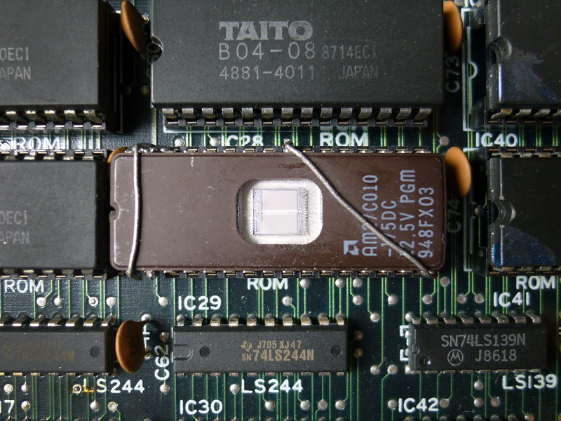
I could replace this bad looking hacked EPROM with a blank TC531000, LH531000 or a HN62331 mask ROM as they seems to have the exact same specs and size than the original mask ROM but it seems nearly impossible to find these chips nowadays.
After comparing the pinouts between 1Mbit 32pins EPROM and 1Mbit 28pins MASK ROM I found what was missing on that hack: pin #2 (A16) of the EPROM was not going anywhere and it should be connected to pin #22 on the socket. I soldered a thin wire on the EPROM and plugged it underneath the chip on the socket.
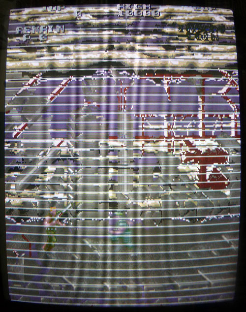
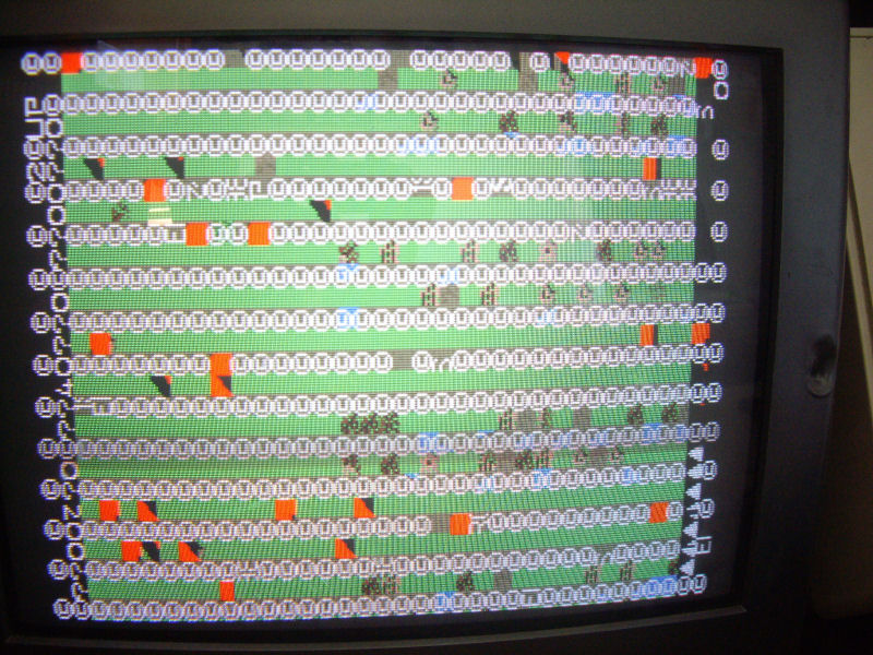
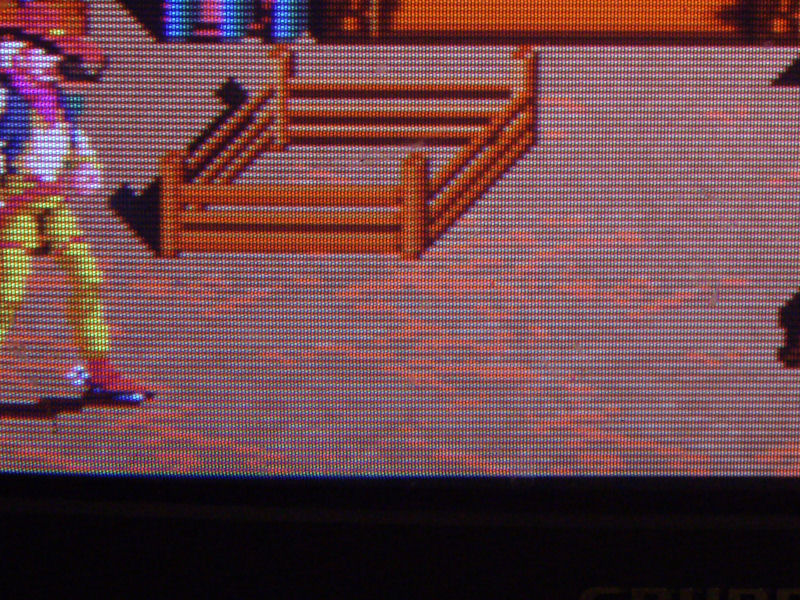
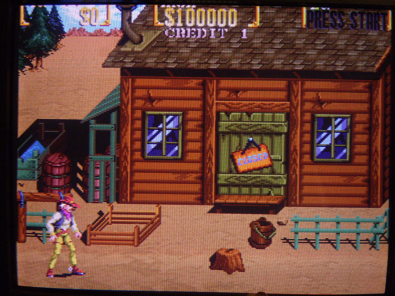
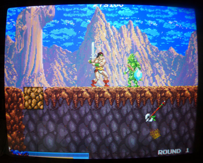
Plugged back the chip and the gfx were then fully fixed ! (as an example, this axe on the bottom-right corner was garbled before):
Alright, BUT… After playing the game for a few minutes, I noticed when dying that Rastan’s voice was suddenly cut and looped 3 times along with his jumping voice. If I had to replace what I heard with words that would make: DYING/cut/JUMPING/DYING/cut/JUMPING/DYING/cut.
Well, that sounded weird so a verification in the emulator confirmed that was not normal.
The test mode features a sound test so I compared all the voices between my board and the game in MAME and there was 3 voices replaced by this looping sound of Rastan’s dying/jumping.
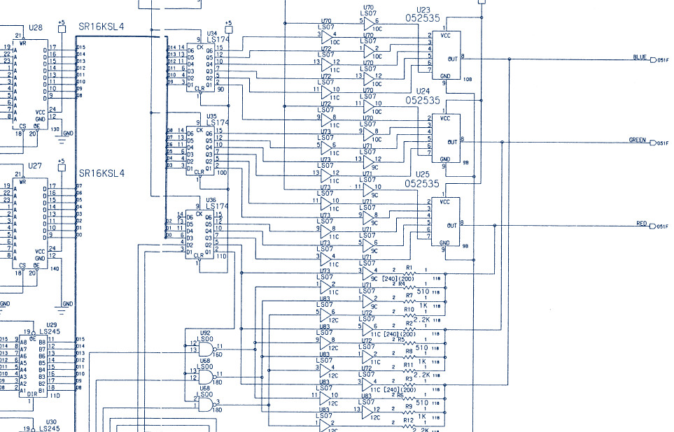
Alright, had to look back at the schematics…
This was (most probably) related to the voice generating part which is pretty small fortunately as it involves only a few TTLs as well as the Z80, one EPROM and one M5205 (ADPCM sound generator).
Sound ROMs were tested OK and every address and data lines looked fine.
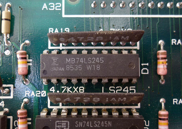
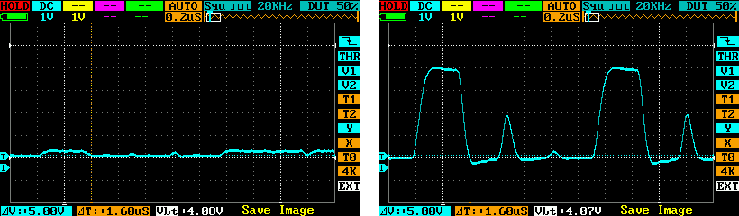
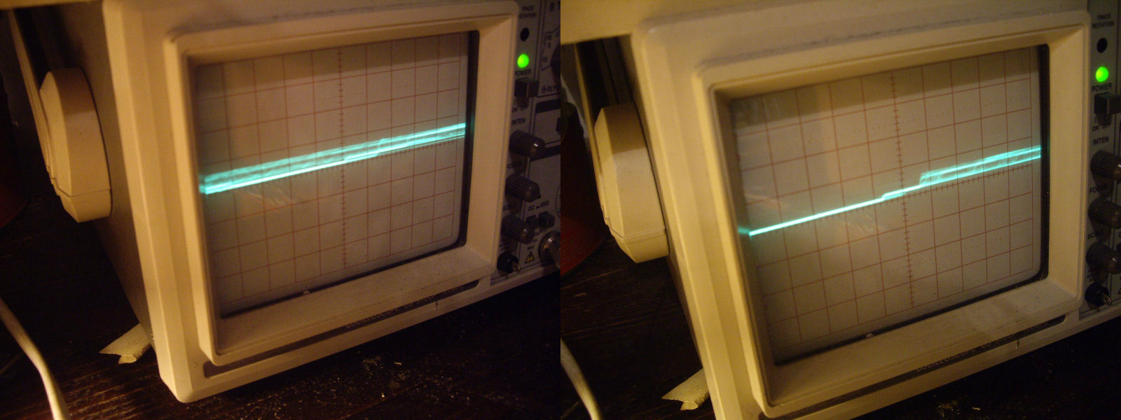
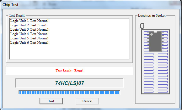
Checking the related TTLs with the scope, I noticed there was no pulsing signals on every of the 5 outputs of the 74LS193 @ IC60 while its inputs were pulsing. This chip is a counter and it is partially doing the link between the sound data bus and the voice address bus. There is another 74LS193 @ IC77 doing the same work for other address/data lines and outputs were pulsing when I pushed the button to generate one of Rastan’s voice in the sound test.
Piggybacking the chip at IC60 made the voices working fine with no weird loop. Also the other voices in the sound test were back. Replaced the chip and finally have now a perfectly working Rastan. (well, played it a few hours and it runs perfectly !)
Thanks to Porchy and Caius for their help on the PAL and hacked EPROM.