I thought this repair was the perfect opportunity to show you how to correctly servicing the ‘infamous’ Konami ‘054986A’ custom audio module (obviously this is valid also for the ‘054544’ one).Follow this guide at your own risk.I’m not responsible for any kind of damage!
Let’s start.
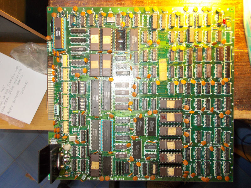
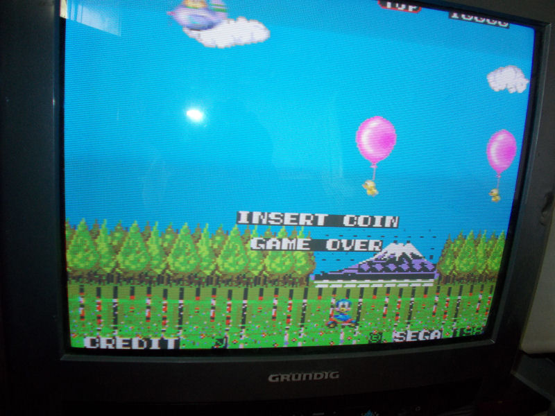
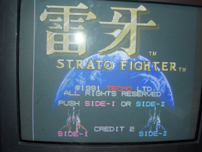
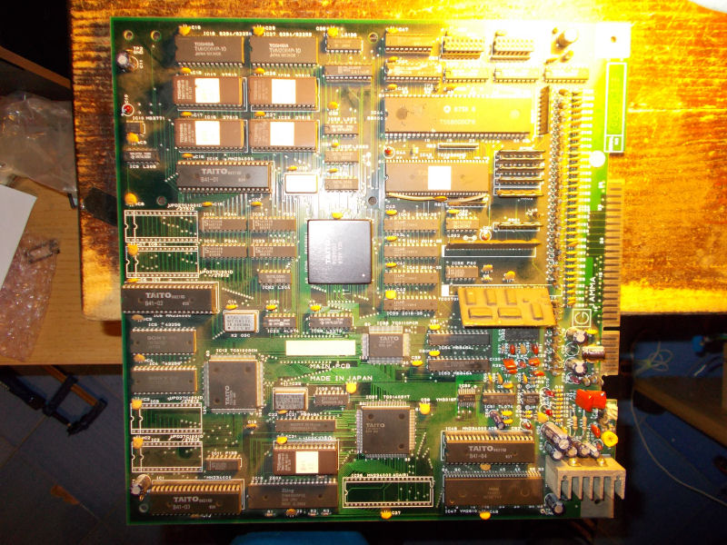
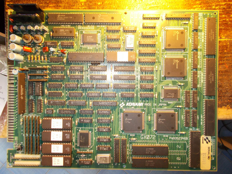
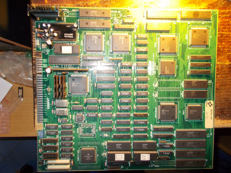
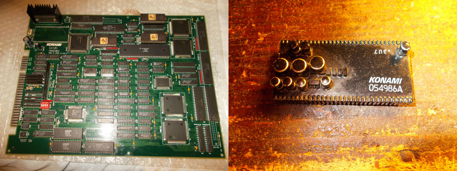
I got from my friend ‘supermik’ this Mystic Warriors PCB:
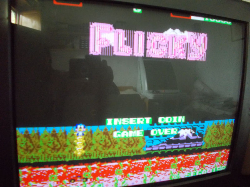
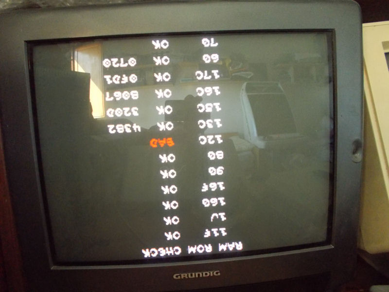
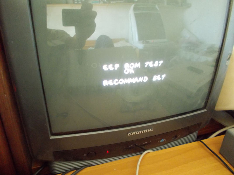
Board played fine but had an orrible sound output, very loud and distorted:
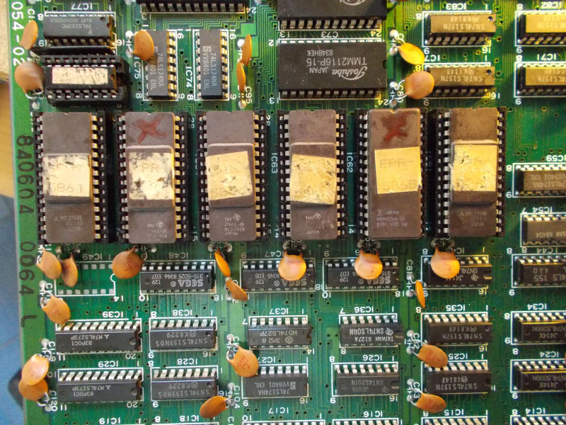
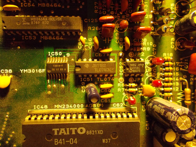
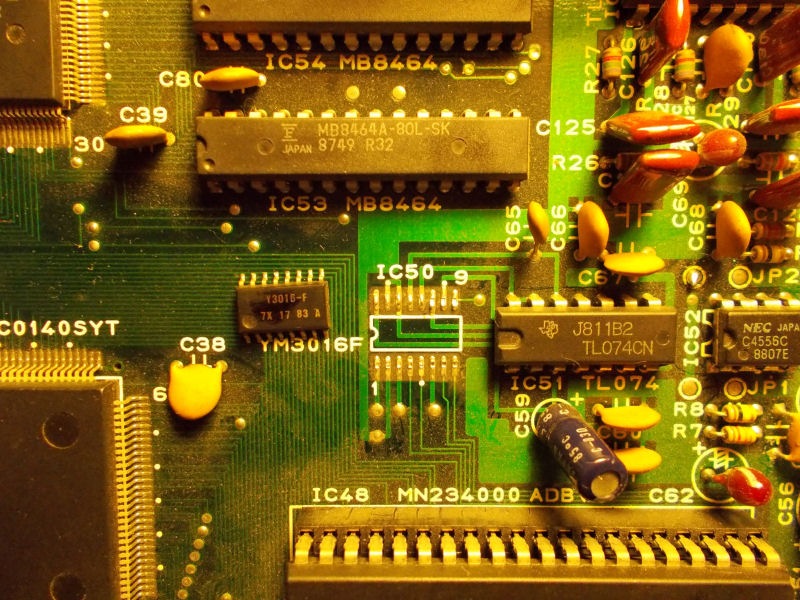
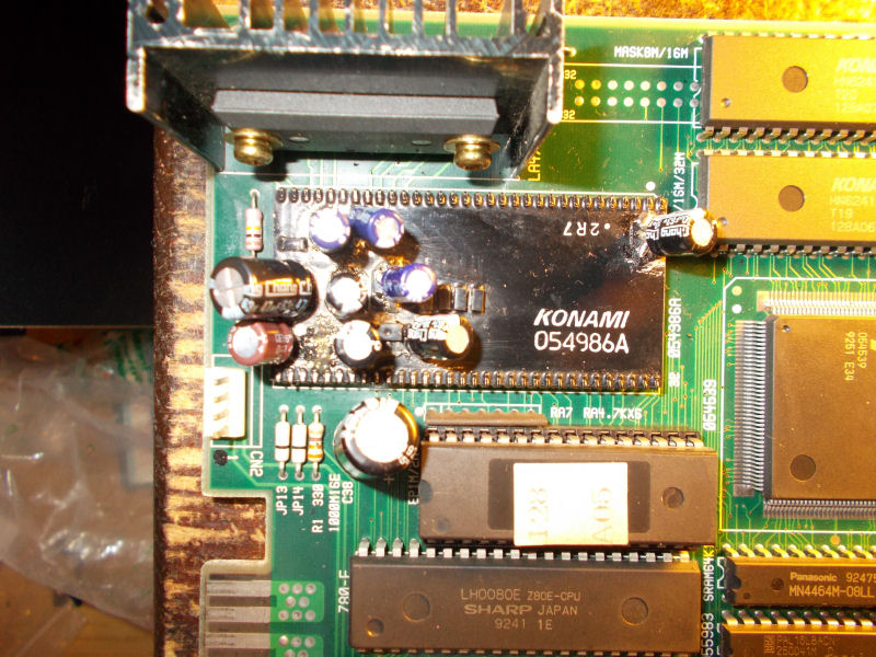
Obviously the culprit was the ‘054986A’ module whose capacitors were replaced by thru-hole electrolityc ones:
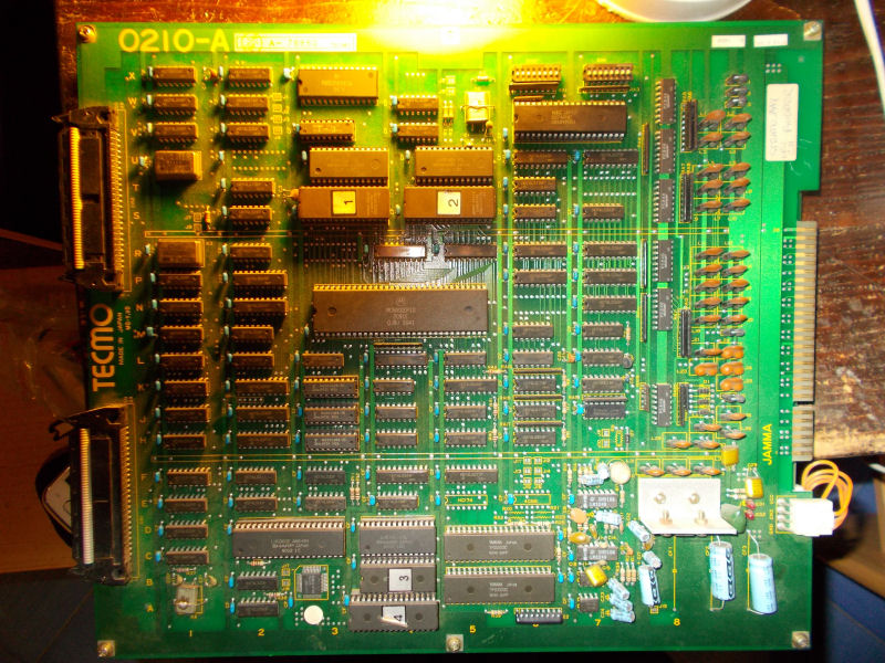
But this was not enough to fix the issue.So, instead of troubleshooting the module (the 4558 OP-AMP and the AD1868R DAC undersneath were most likely bad), I opted for its complete replacement using a Premiere Soccer as donor board :
The removal of a module consists in the following steps:
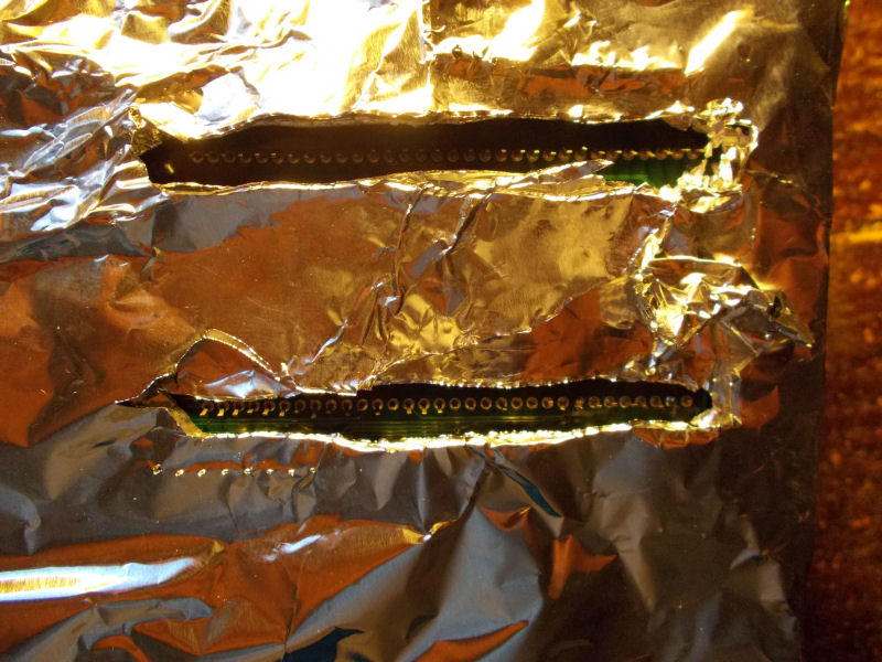
Prepare the board by covering the solderside with some aluminium foil leaving exposed only the pins of the module:
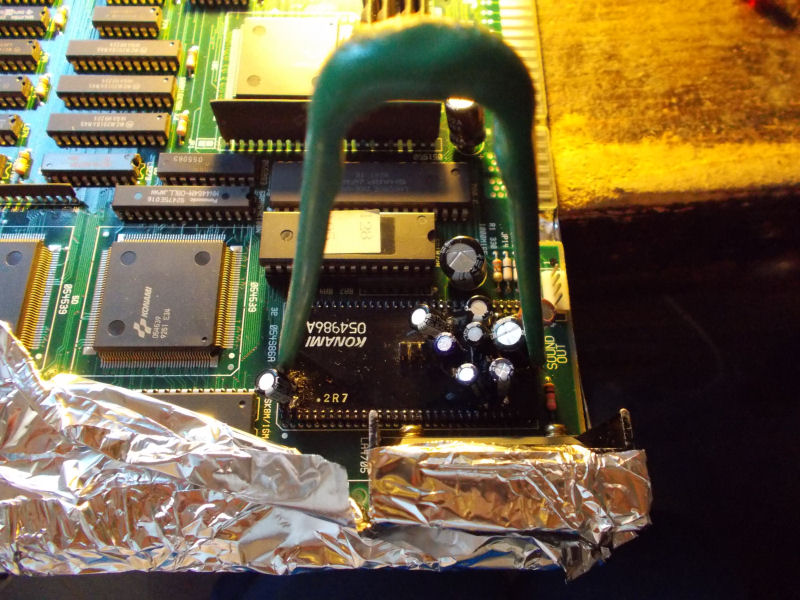
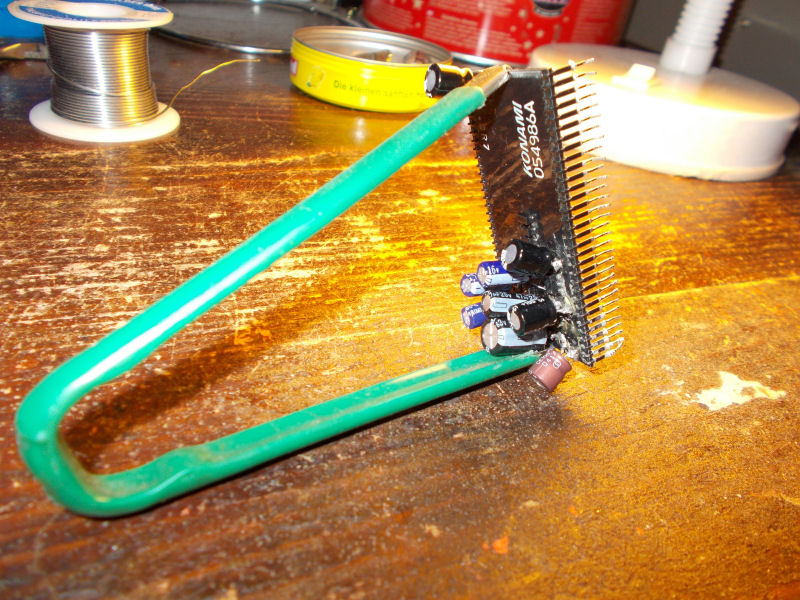
Clamp an IC extractor on the sides of module:
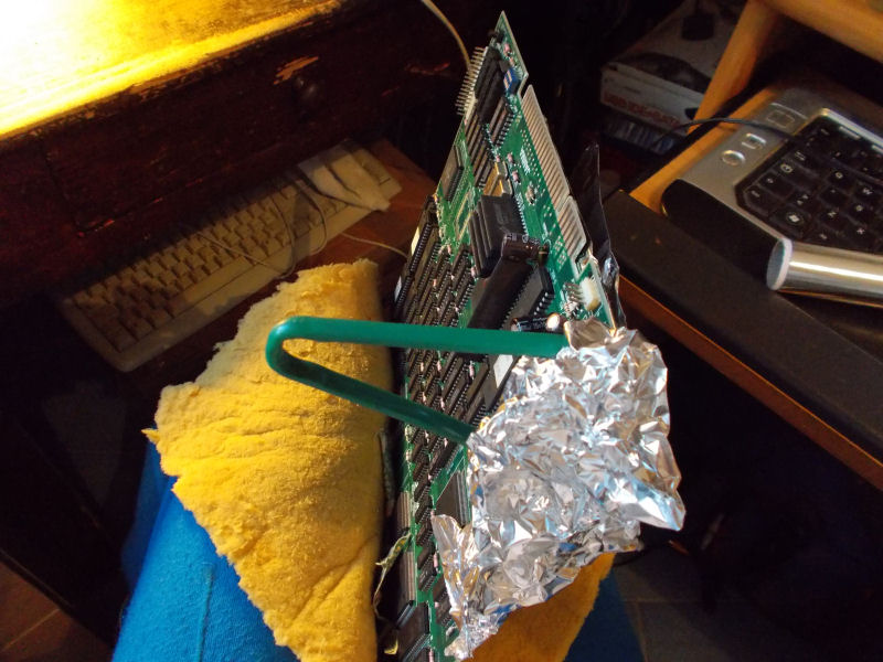
Put the board wrapped in a cloth or pillow between your legs:
Now, with an hot air rework station do a first preheating of a couple of minutes on the exposed solderside setting the temperature at 100 Celsius degrees.Then, set the station at 250 degrees for a minute or less:
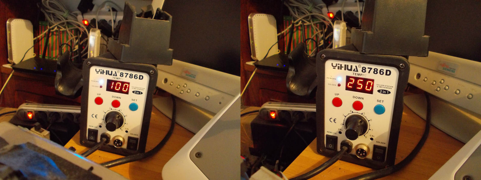
In both cases, you have to move the hot air gun back and forth without stopping otherwise you could damage the board.
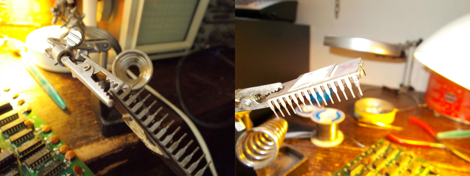
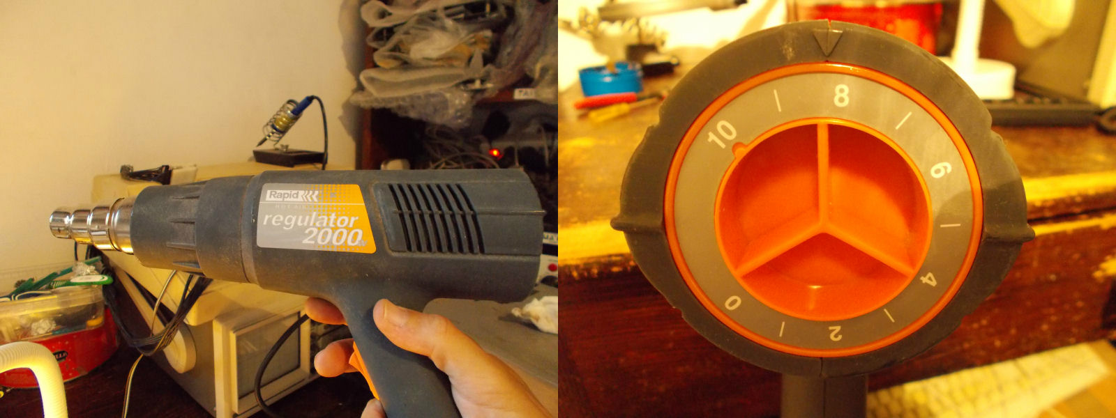
After done this preheating (needed to facilitate the solder melting and avoid heat stress) you have to use an heat gun for the last pass.Personally I use a 2000Watt model and set the temp to position ‘8’:
Keep moving the gun back and forth and at same time gently pull the IC extractor:
When the solder will arrive at the melting point, the module will come out easily from its seat:
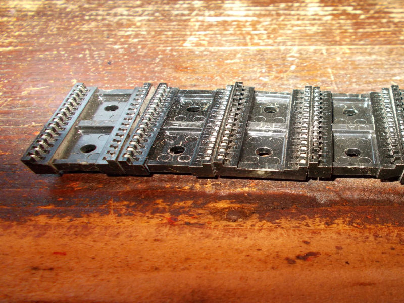
Next step is the sockets installation, use 1.78mm pitch ones (cutting a single socket in half):
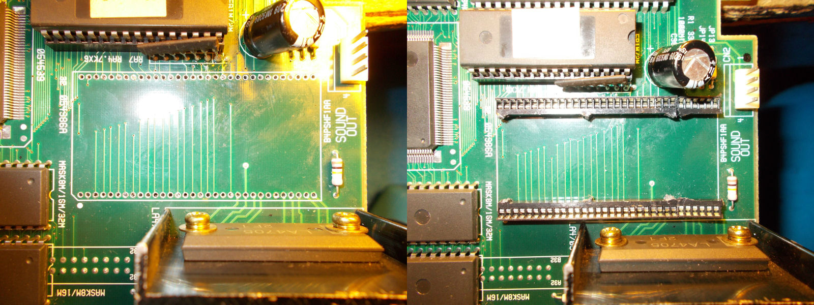
Lastly, mount your good module and you are set.
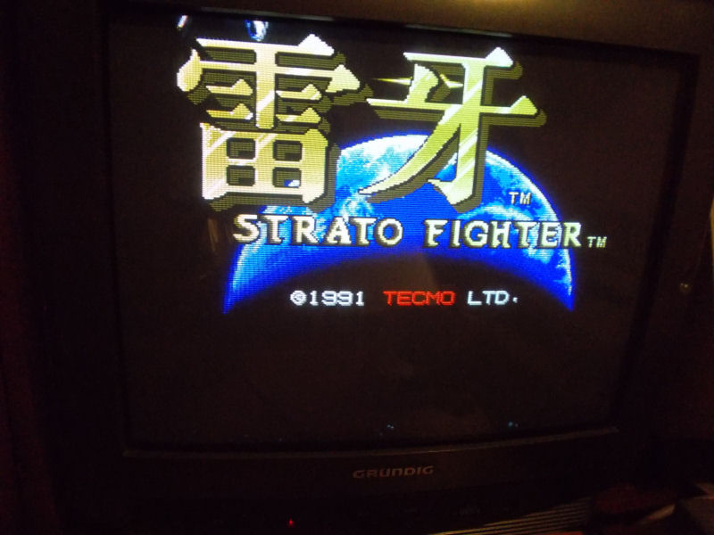
Ah, I forgot..board 100 fixed!