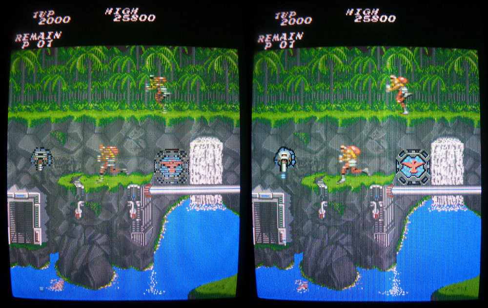
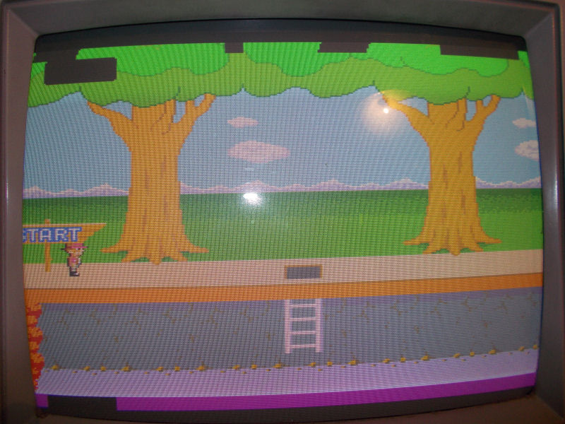
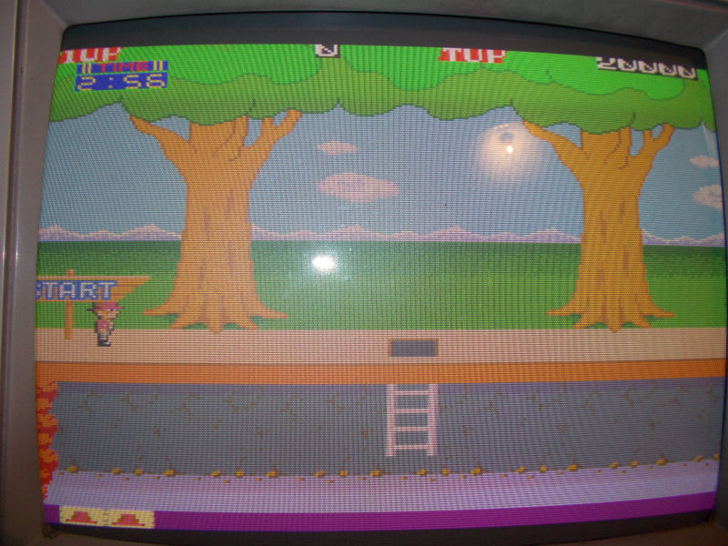
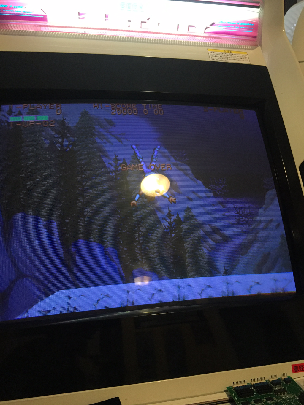
A friend got a Gryzor PCB working but with problems on some of the sprites (mostly enemies and items with half of the horizontal lines missing).
The 4 GFX MASK ROMs were tested ok on another Gryzor PCB. Looking with the scope on the RAMs revealed nothing really suspicious.
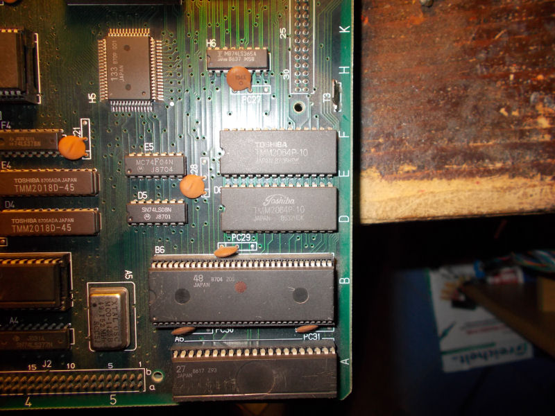
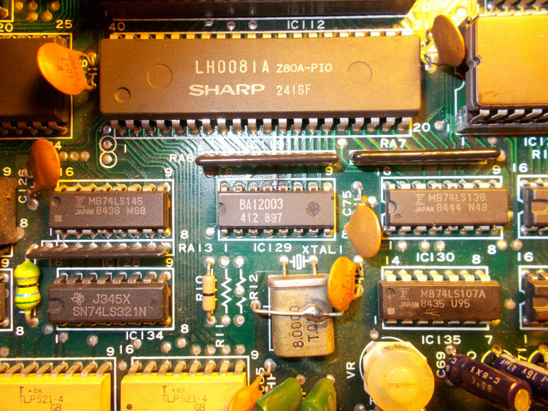
I then piggybacked the RAMs around the GFX part and quickly found the faulty one.
It was the NEC 8644FU12 at location 14G. This RAM is a 4464 (64k-word x 4-bit, same type than the ones I replaced on my recently repaired Final Star Force).
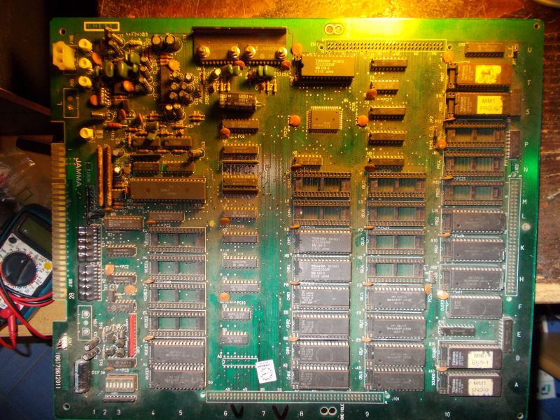
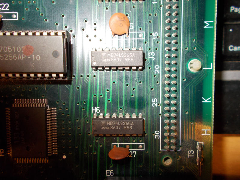
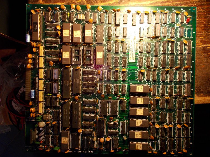
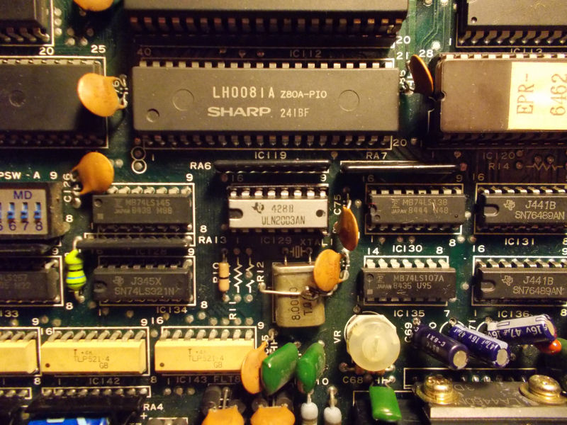
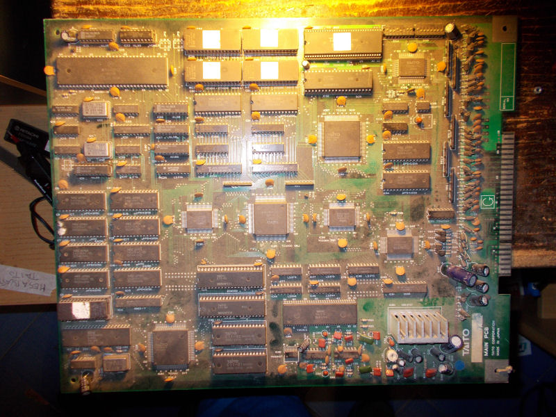
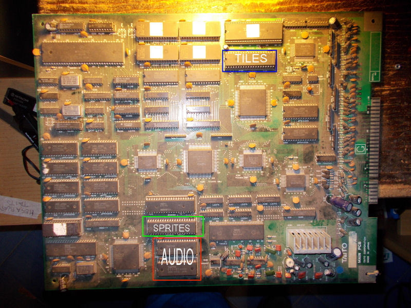
Here is a picture of the PCB with the faulty chip highlighted in red:
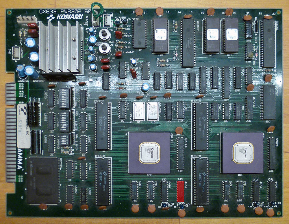
Piggybacking it with a compatible TMS 4464-12 restored all the sprites.
In fact, the problem was so small that it was impossible to see any suspicious signal on any of the pins of that RAM with the scope (every signal looked healthy). I replaced the chip and obviously got the PCB running perfectly.
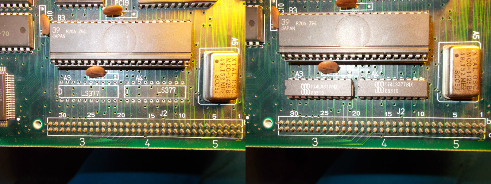
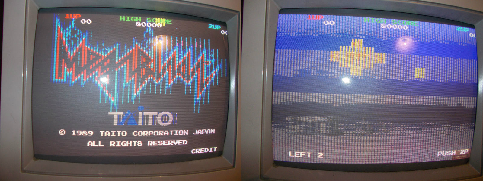
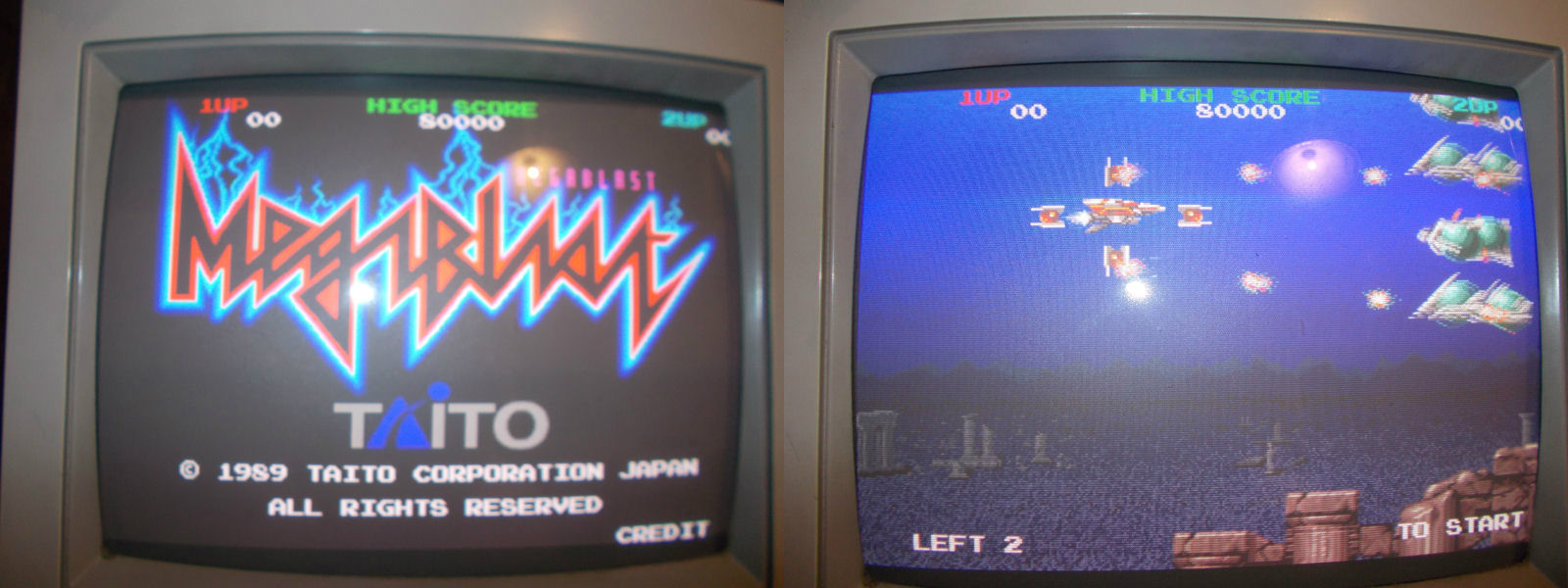
Here is a before and after picture: