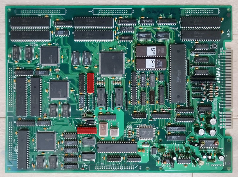
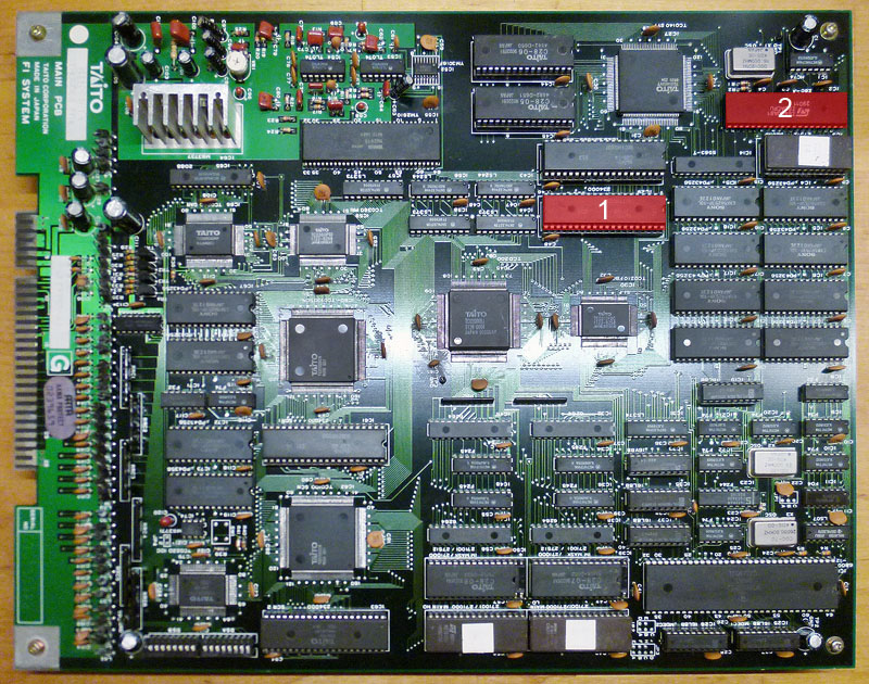
I had since ages this untested Phoenix PCB (manufactured by Logitec Co.,Ltd so not the Taito/Centuri version but same layout of it)
Time to build the needed adapter and I powered the board up with this scenario:
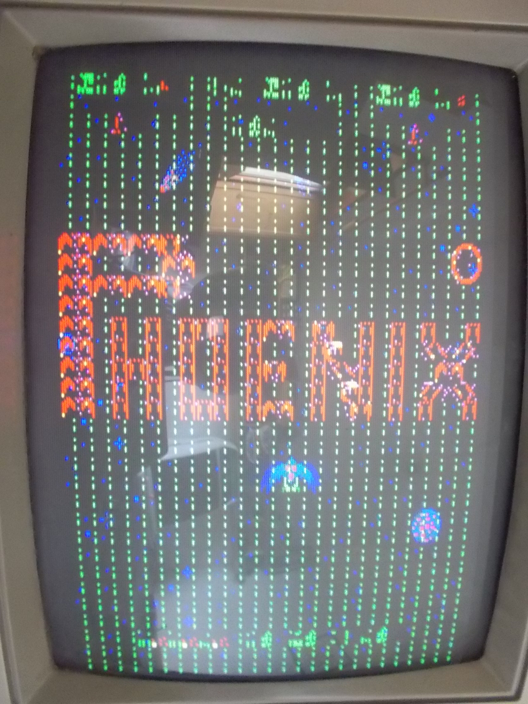
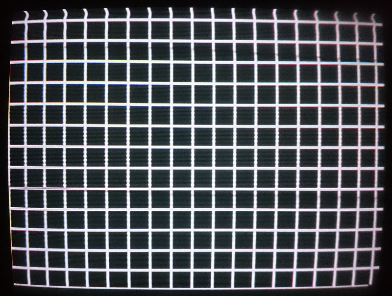
All the screen was filled with a pattern of lines and dots.For first I went to dump all the ROMs on the logic board.Doing a comparison with the MAME dumps I got this result:
001.ic45: used in Phoenix (Irecsa / G.G.I Corp, set 2) renamed phoenix.46
002.ic46: used in Phoenix (Irecsa / G.G.I Corp, set 2) renamed phoenix.46
003.ic47: used in Phoenix (Irecsa / G.G.I Corp, set 2) renamed phoenix.47
004.ic48: used in Phoenix (Irecsa / G.G.I Corp, set 2) renamed 01.ic48
005.ic49: used in Phoenix (Irecsa / G.G.I Corp, set 2) renamed phoenixc.49
006.ic39: used in Phoenix (Irecsa / G.G.I Corp, set 2) renamed h6-ic50.6a
007.ic51: used in Phoenix (Irecsa / G.G.I Corp, set 2) renamed h7-ic51.7a
008.ic52: used in Phoenix (Irecsa / G.G.I Corp, set 2) renamed phoenixc.52
009.ic50: used in Phoenix (Irecsa / G.G.I Corp, set 2) renamed phoenixc.39
010.ic40: used in Phoenix (Irecsa / G.G.I Corp, set 2) renamed phoenixc.40
11.ic23: used in Phoenix (Irecsa / G.G.I Corp, set 2) renamed ic23.3d
12.ic24: used in Phoenix (Irecsa / G.G.I Corp, set 2) renamed ic24.4d
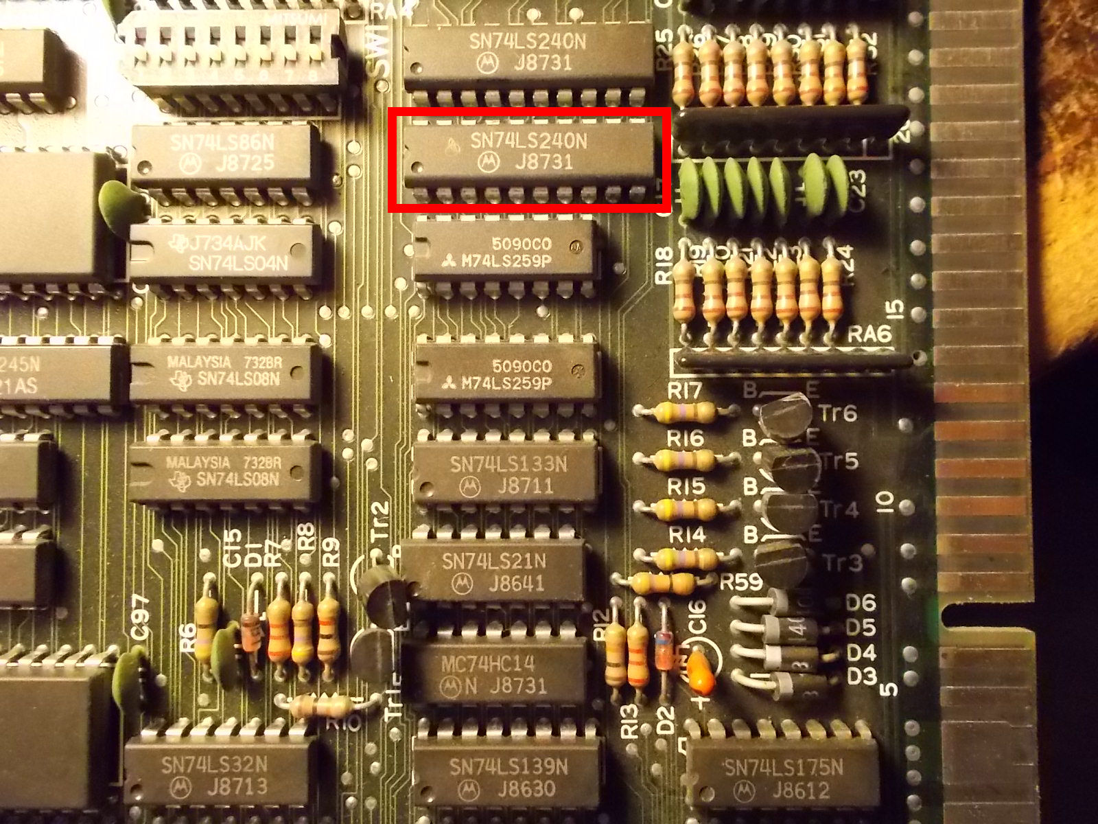
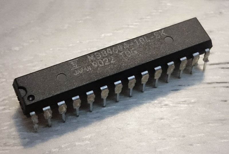
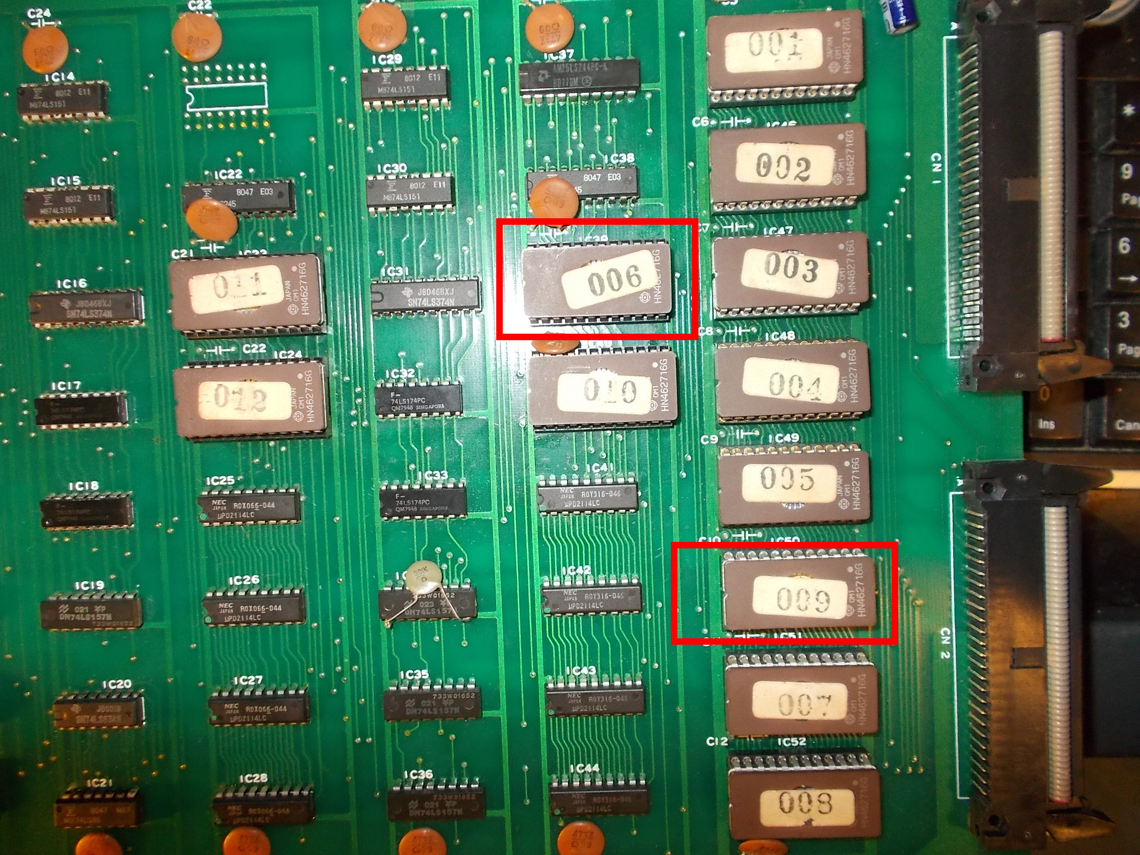
All my ROMs matched this MAME set but the two highlighted in the above list were swapped in their sockets, you can clearly notice it in the following picture :
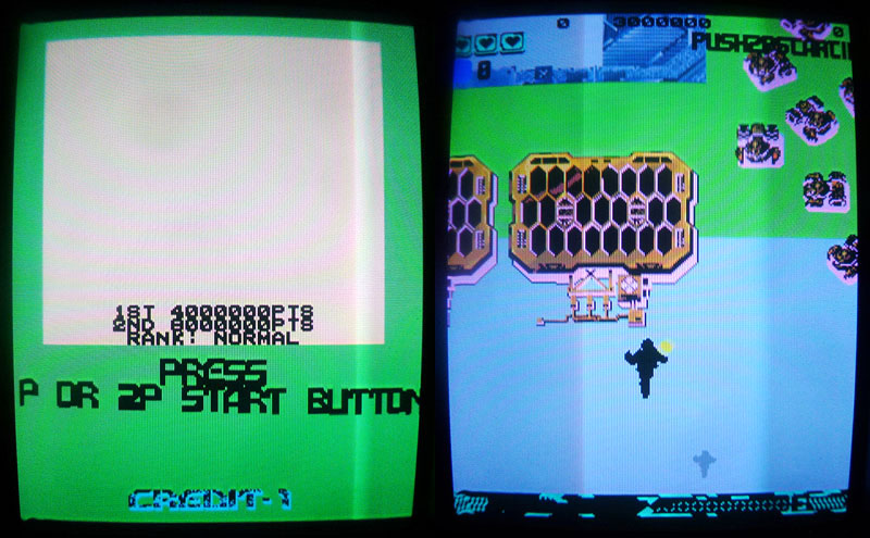
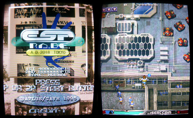
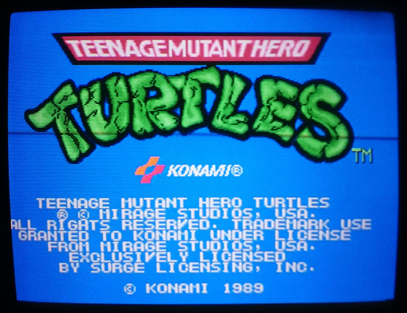
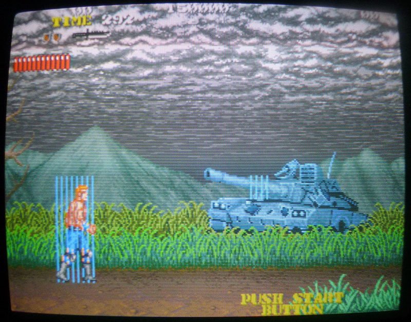
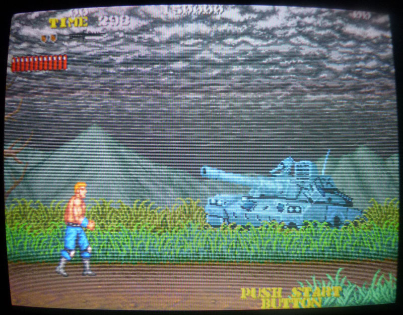
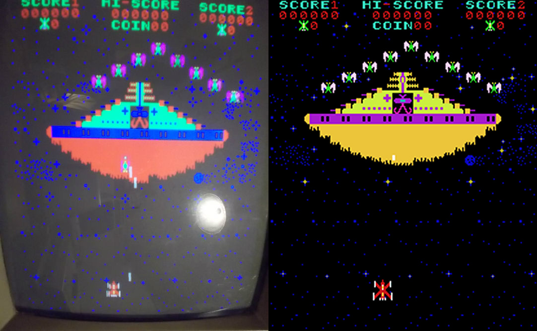
 Putting the two ROMs in right location restored the graphics but colors were wrong, here’s a comparison with a MAME screenshot on the right:
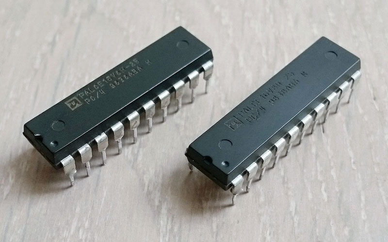
According to MAME source, low and high bits of the palette come from two bipolar ROMs @IC40 and IC41 :
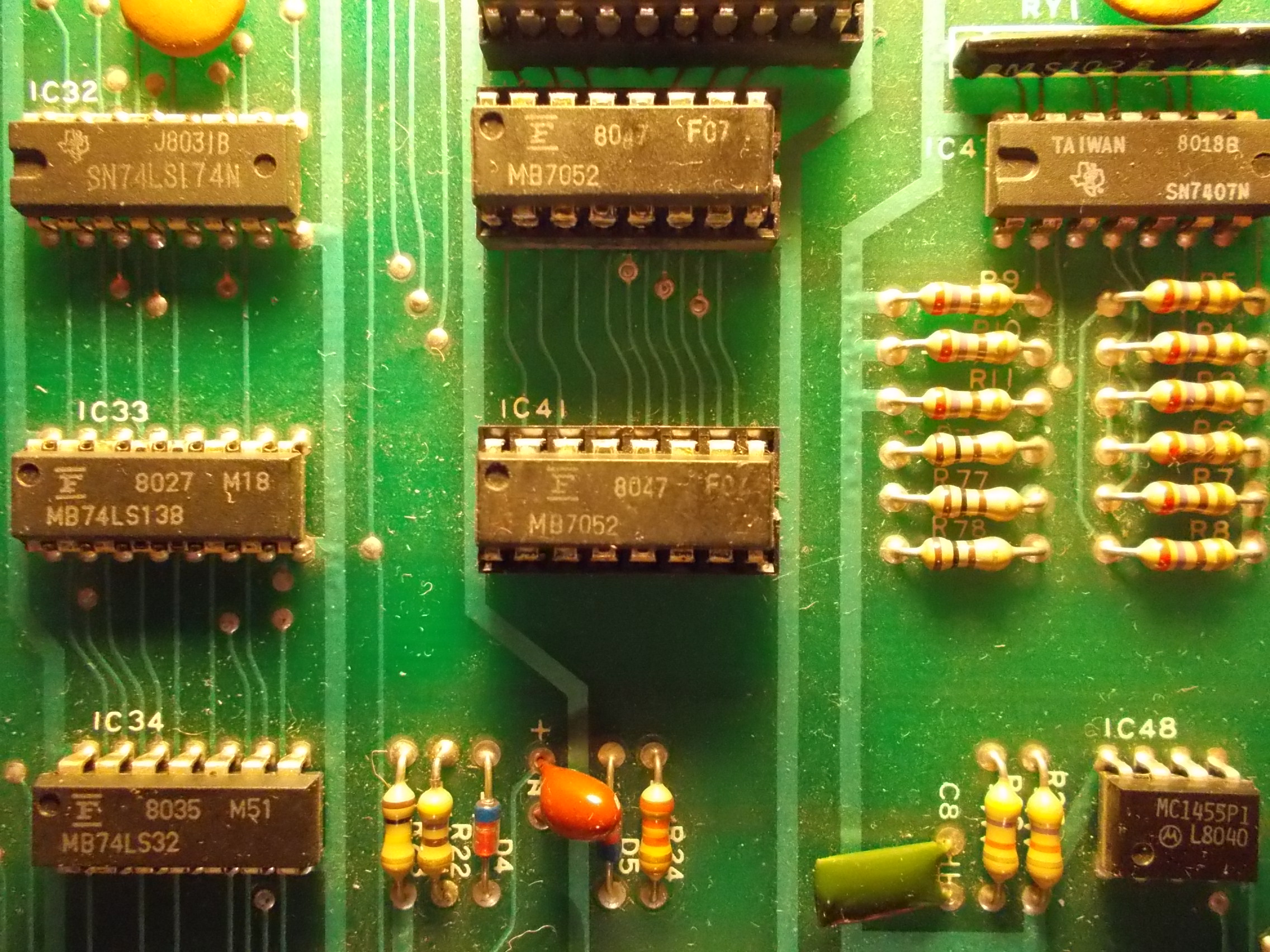
I dumped them and, like the two EPROMs, they were put by someone in wrong socket:
ic40: used in Phoenix (Irecsa / G.G.I Corp, set 2) renamed mmi6301.ic41
ic41: used in Phoenix (Irecsa / G.G.I Corp, set 2) renamed mmi6301.ic40
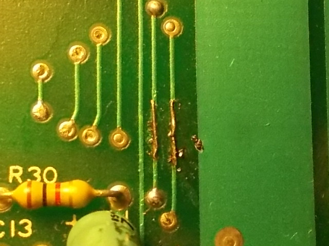
Repositioned the BPROMs, colors came back to normal but, when I was playing the game, I noticed two further issues : shield (button two) of player 1 and 2 was not working, tracing back the involved pins from JAMMA connector I promptly found the cause:
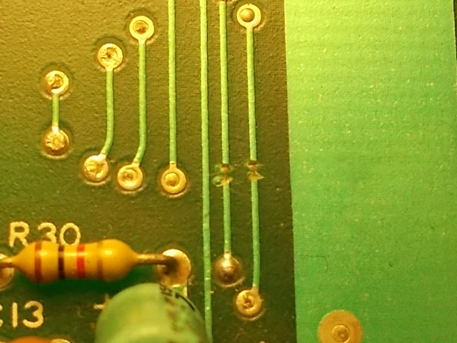
Traces were severed, perhaps from some operator to make the game harder ( and earn more money..).I patched them with a bit of AWG30 wire:
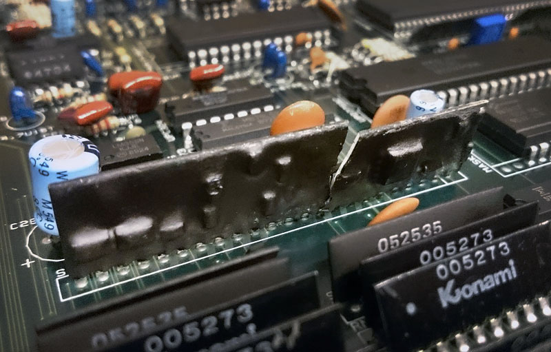
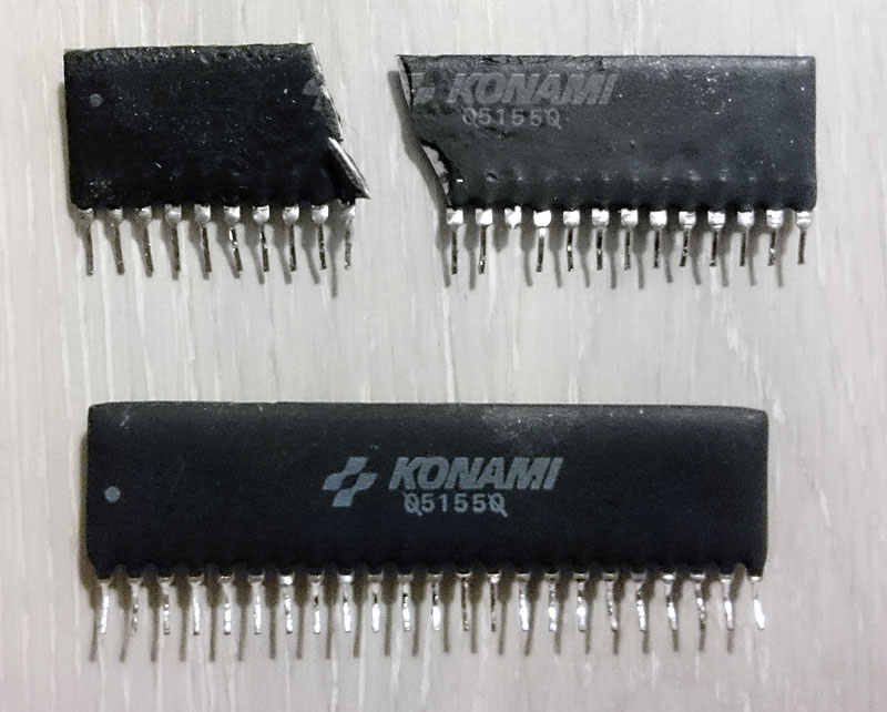
The other issue concerned the audio, some effects (like shots and explosions) were missing replaced by some whistling sounds:
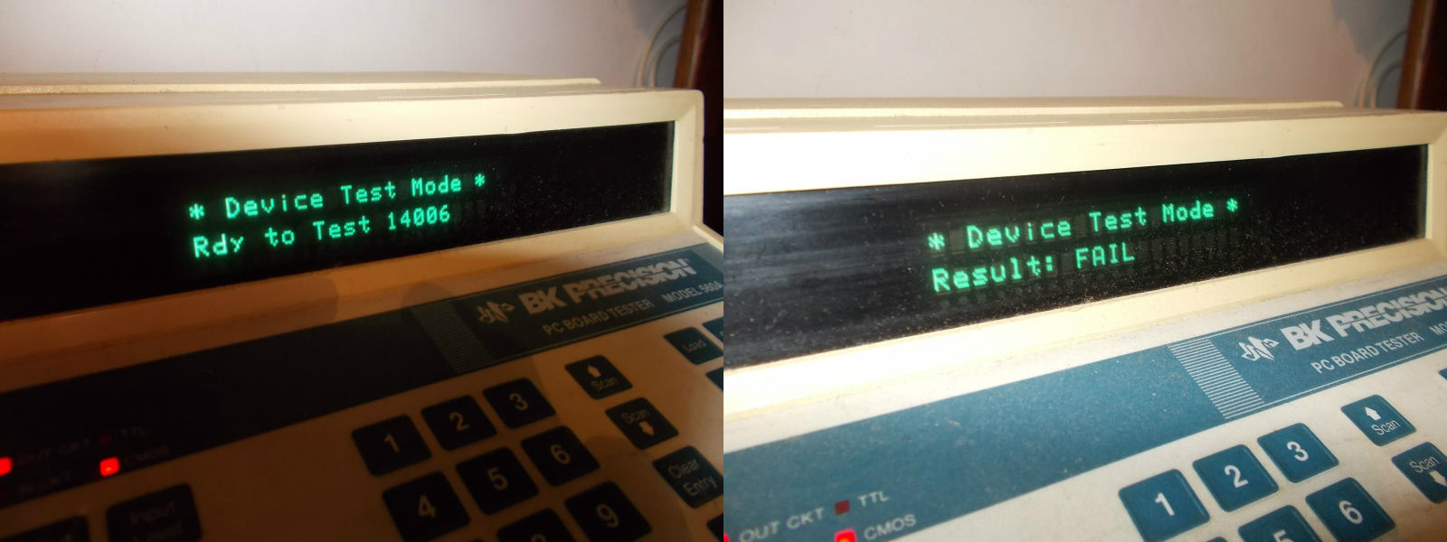
With the help of schematics I could figure out that these sounds were generated by a 4006 shift register @IC45:
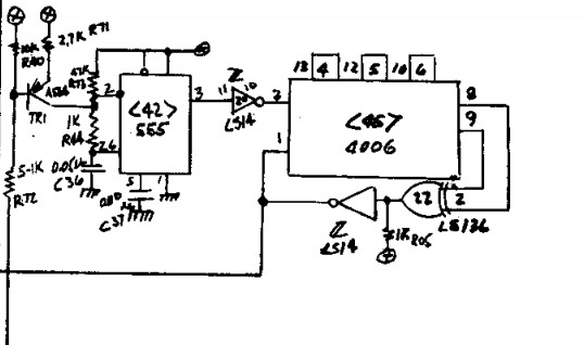
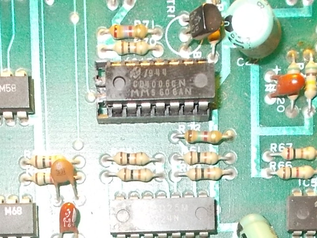
Clock were present on pin 3 when sounds were triggered but all its outputs were stuck high or low (and totally missing on pin 10).
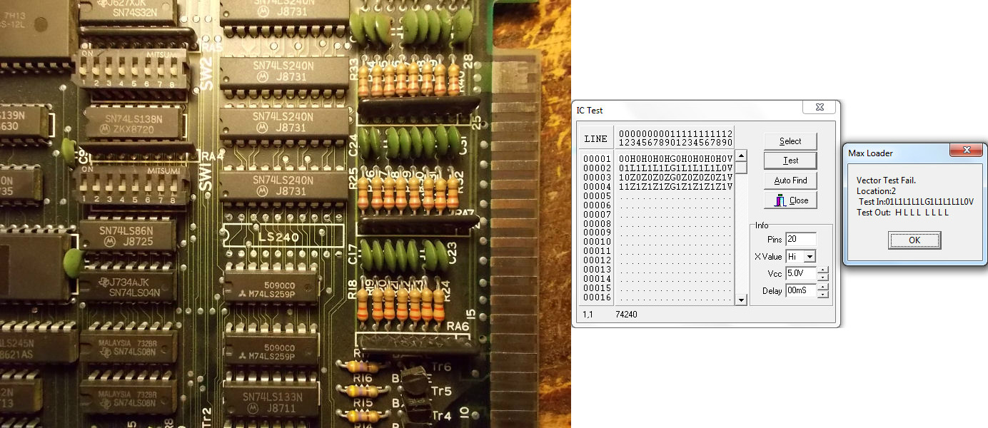
Since device was already socketed I tested it out-of-circuit in my BK560A where it failed:
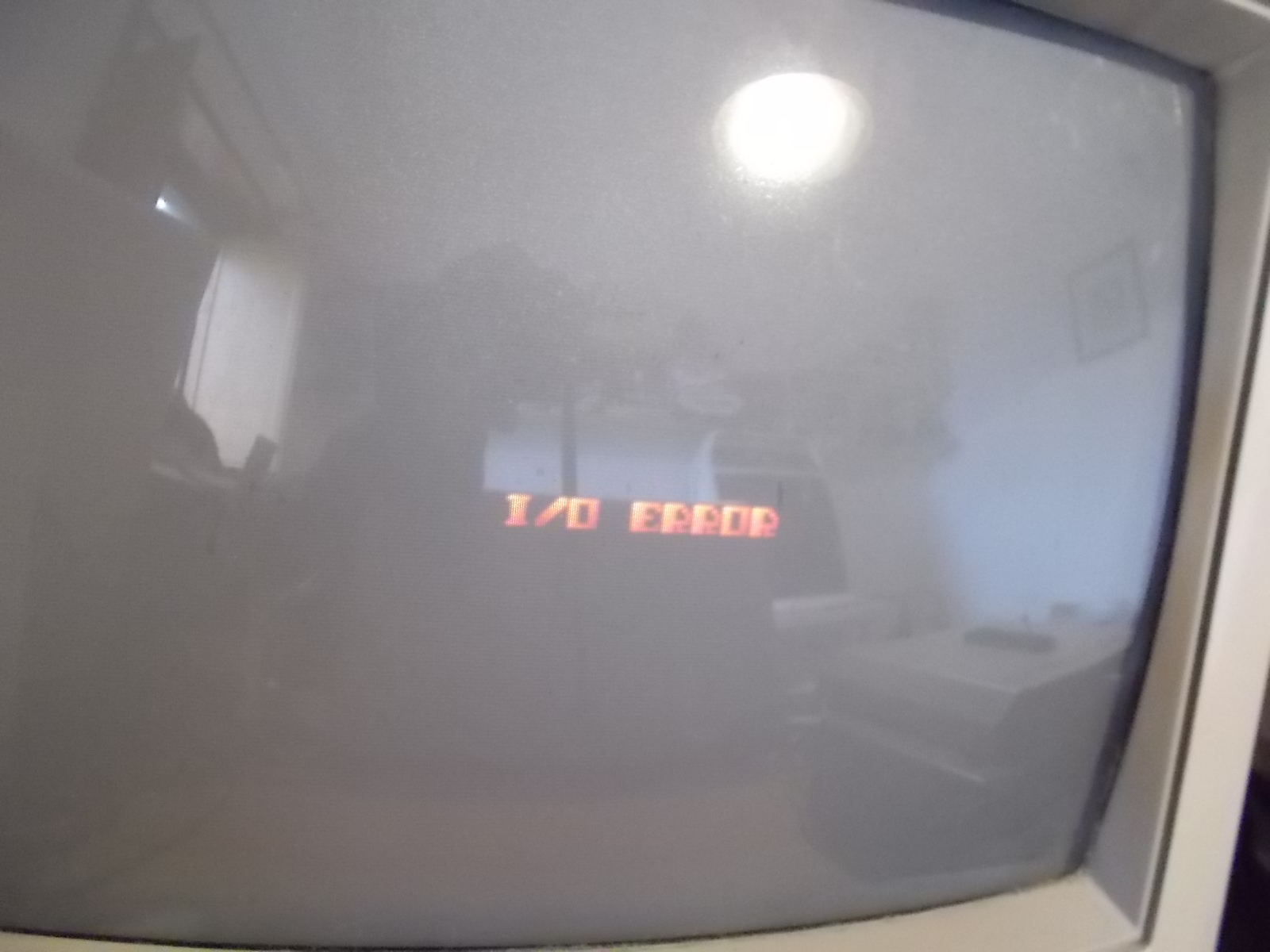
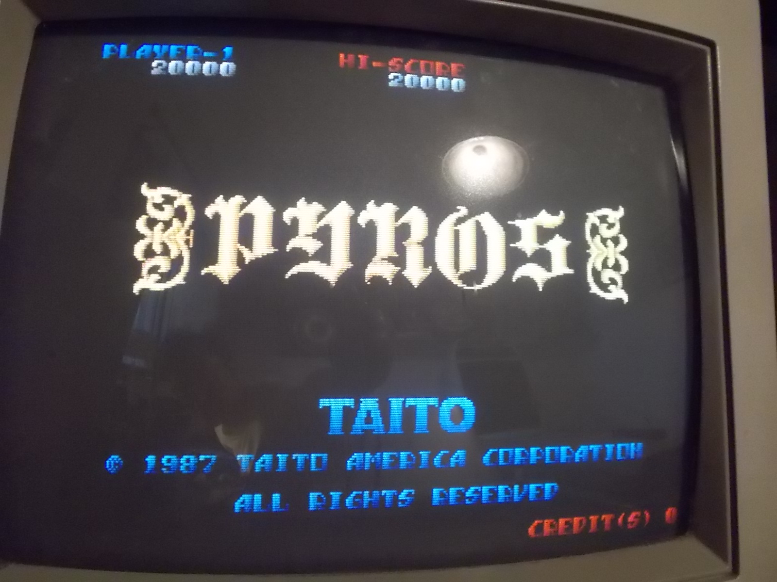
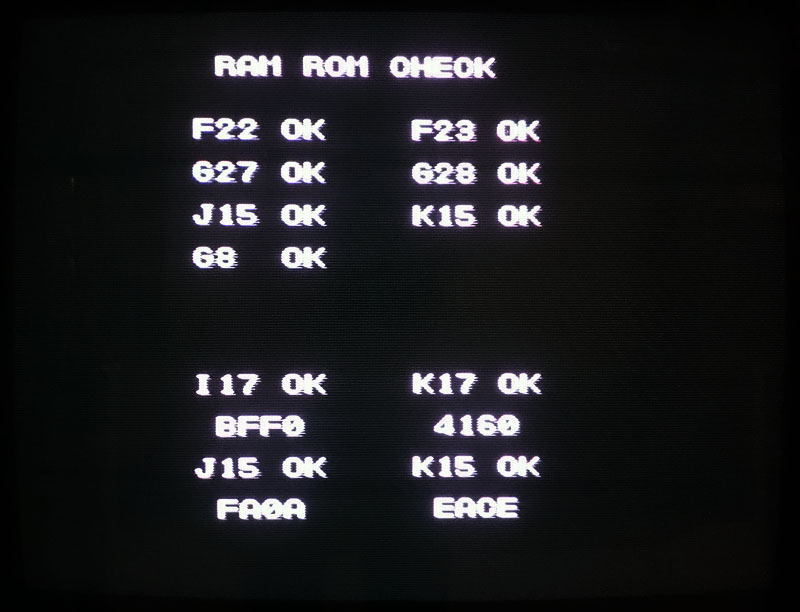
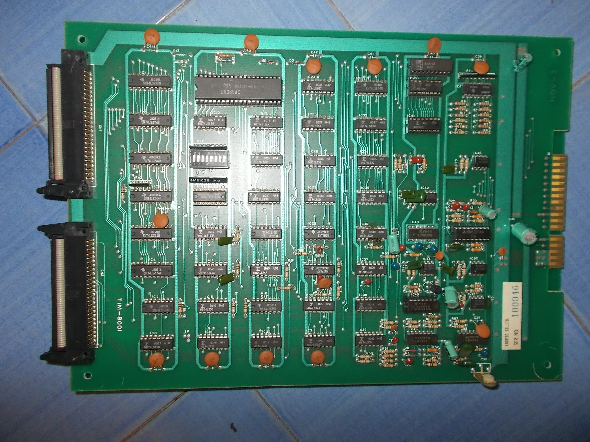
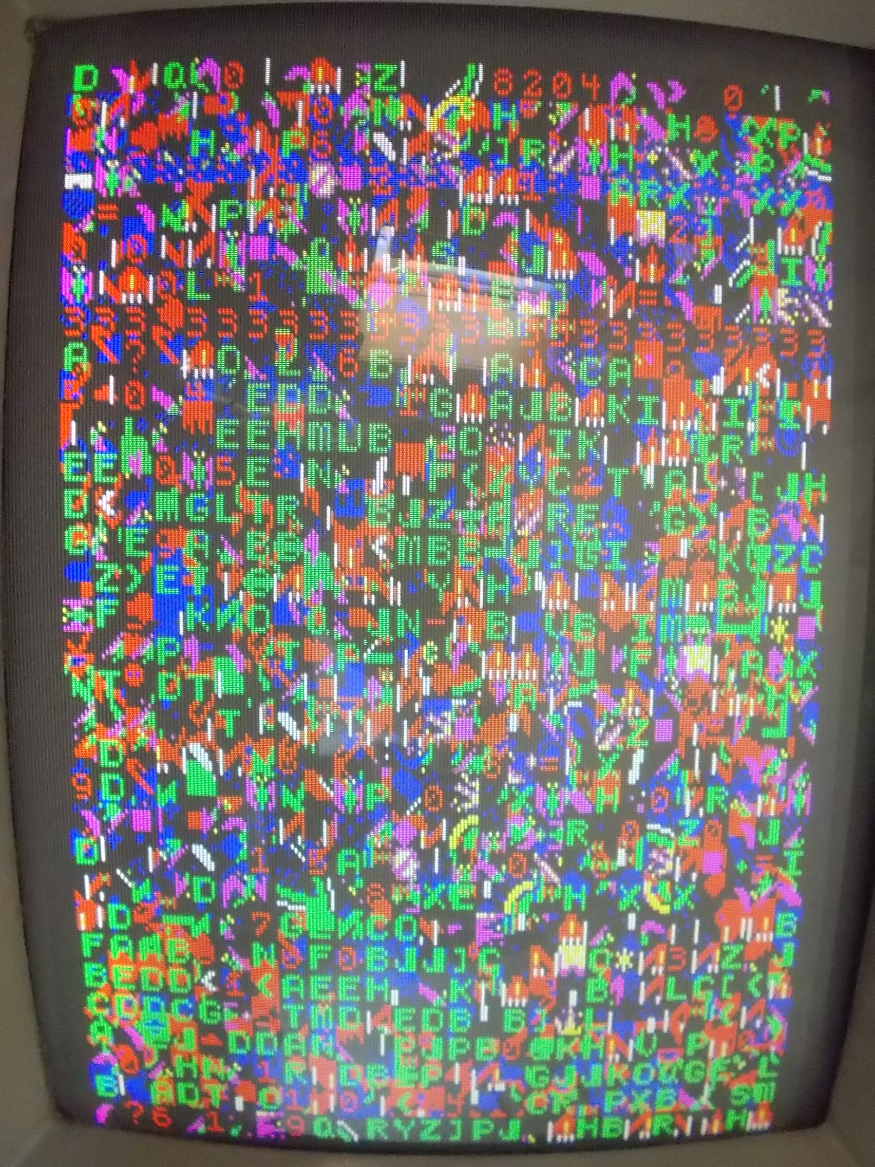
With a good IC all the sounds were restored but, before closing this repair, I noticed that the board was randomly missing the boot staying stuck on this garbage screen :
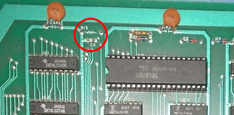
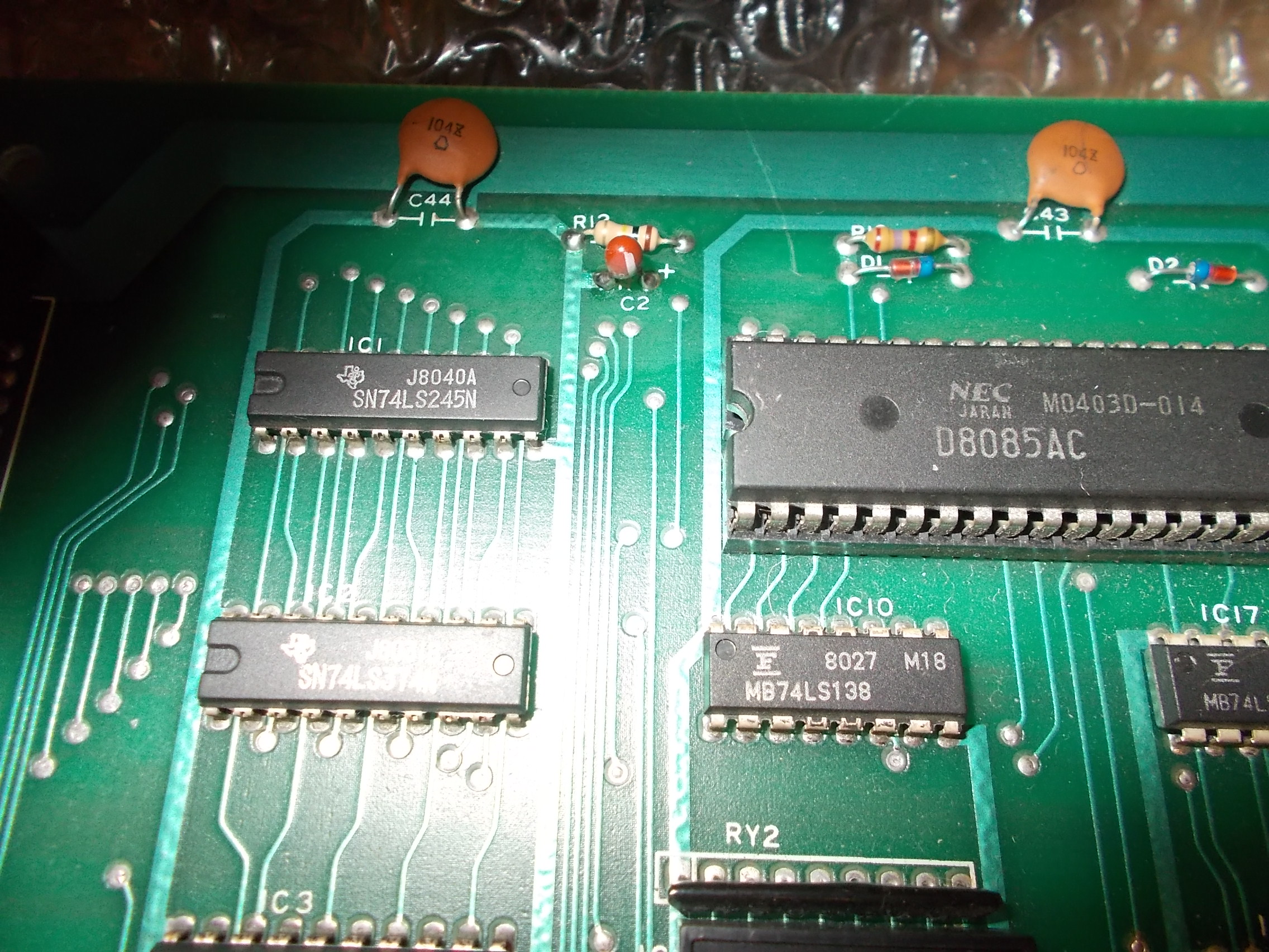
Doing a visual inspection I noticed a missing resistor @R13 and capacitor @C2 near the 8085 main CPU :
Checking the schematics these were involved in RESET circuitry:
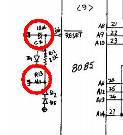
The service manual reported them as a 10uF tantalum capacitor and a 100Ohm resistor.:
![]()
![]()
so I promtly installed these parts :
No more missing boot and fully working board!