Lately, I got a total of 4 faulty Night Slashers PCBs from friends to repair. Due to the fact that these boards are mainly populated by SMCs and customs ICs, a custom CPU and no available schematics, making them less handy to diagnose than some older generation boards. I decided to take advantage of having four boards on the bench and recently started working on them.
Among the 4 boards, I had three different board revisions (DE-0395-1, DE-0396-0 and DE-0397-0) only with very minor differences between each.
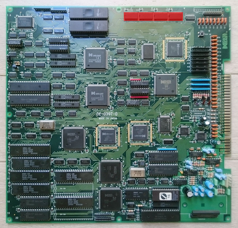
- FIRST FAULTY BOARD (DE-0397-0 revision)
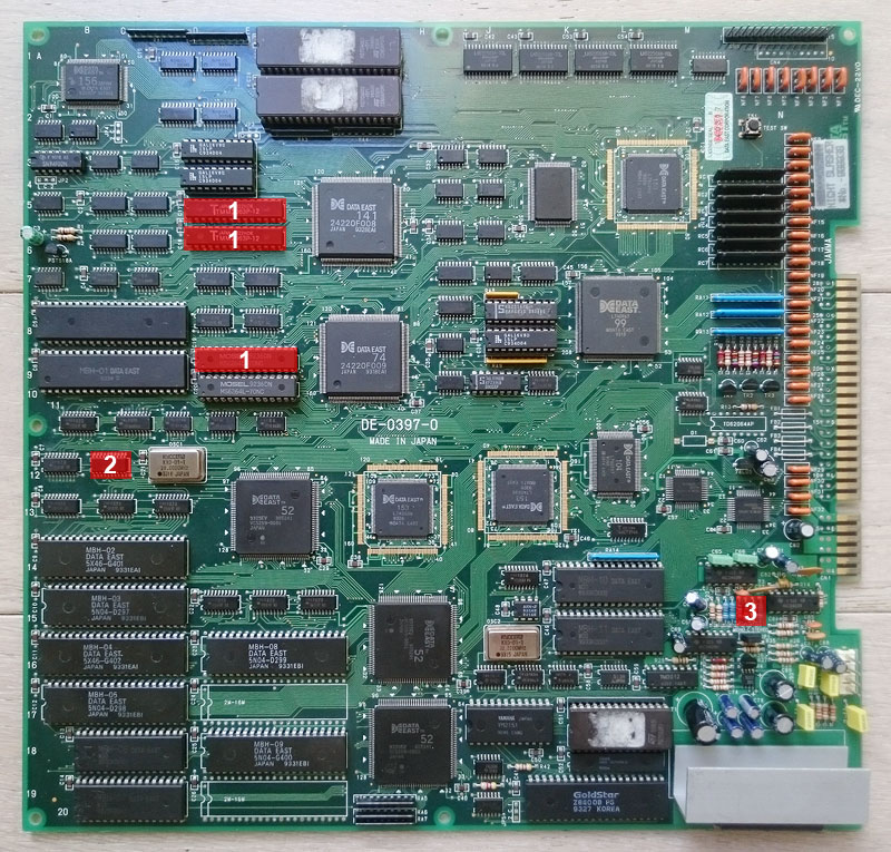
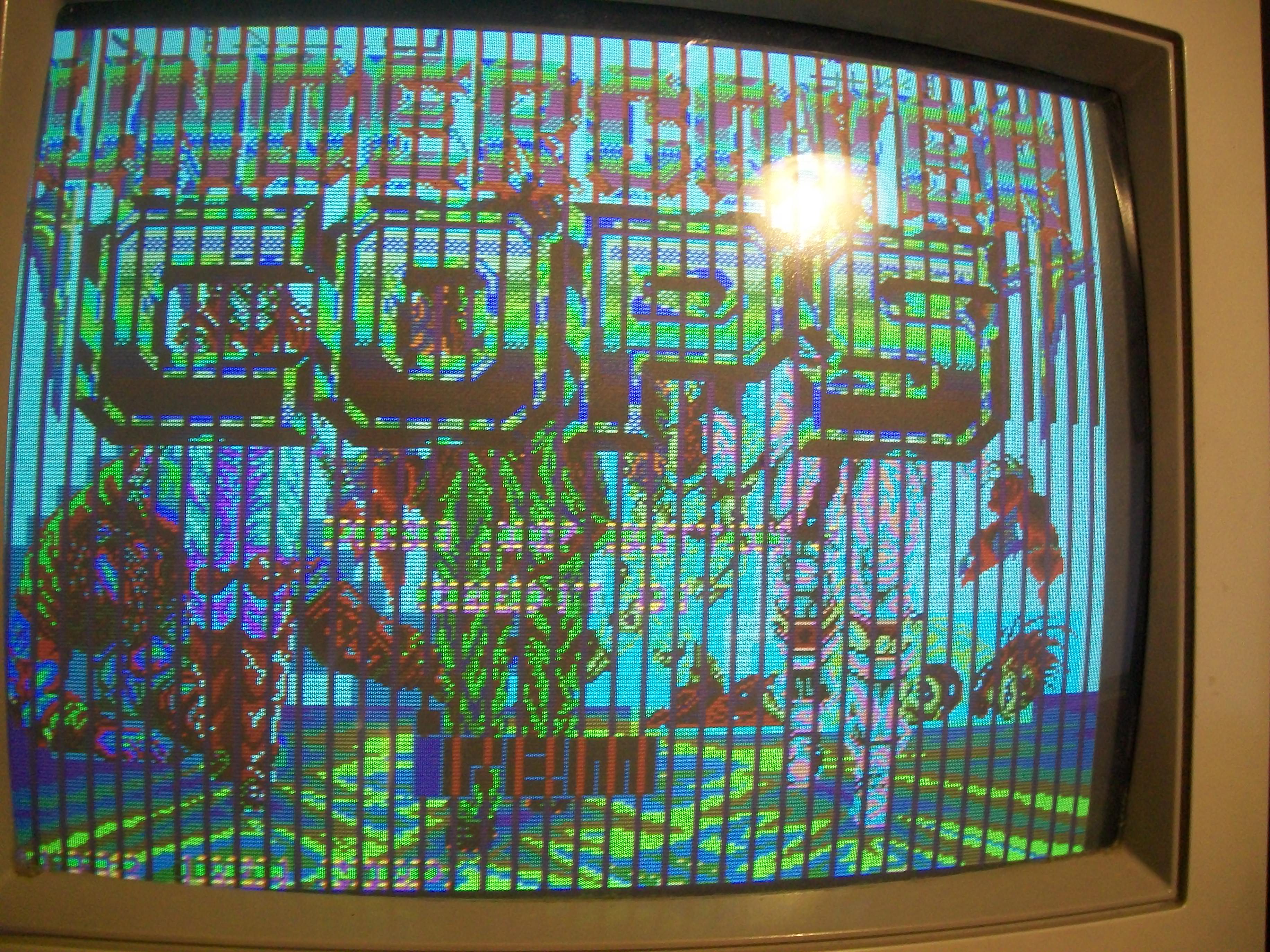
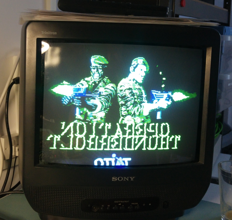
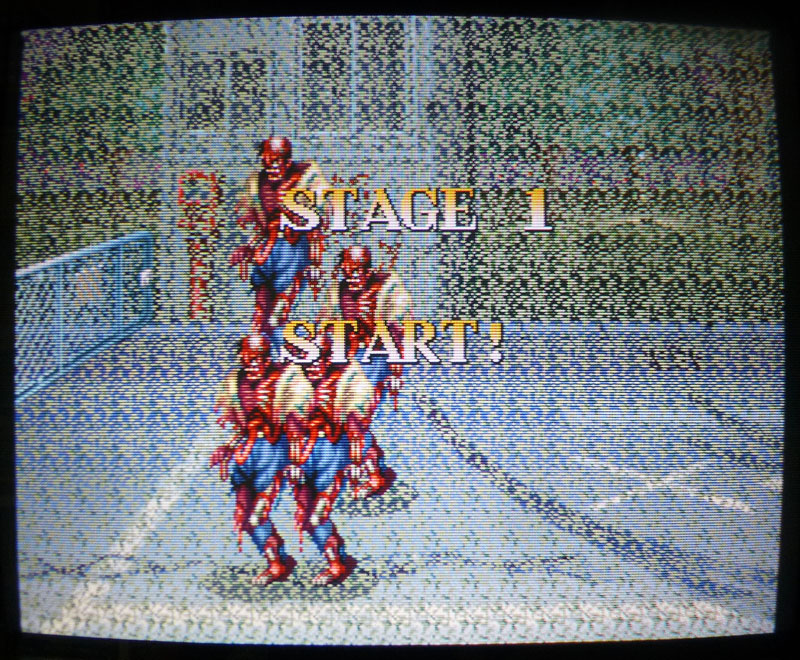
– Problem #1: The game was running but with major gfx issues. Most of the backgrounds were just plain while sprites seemed fine.
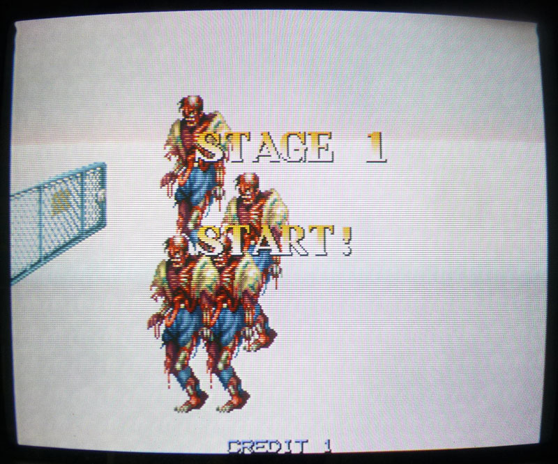
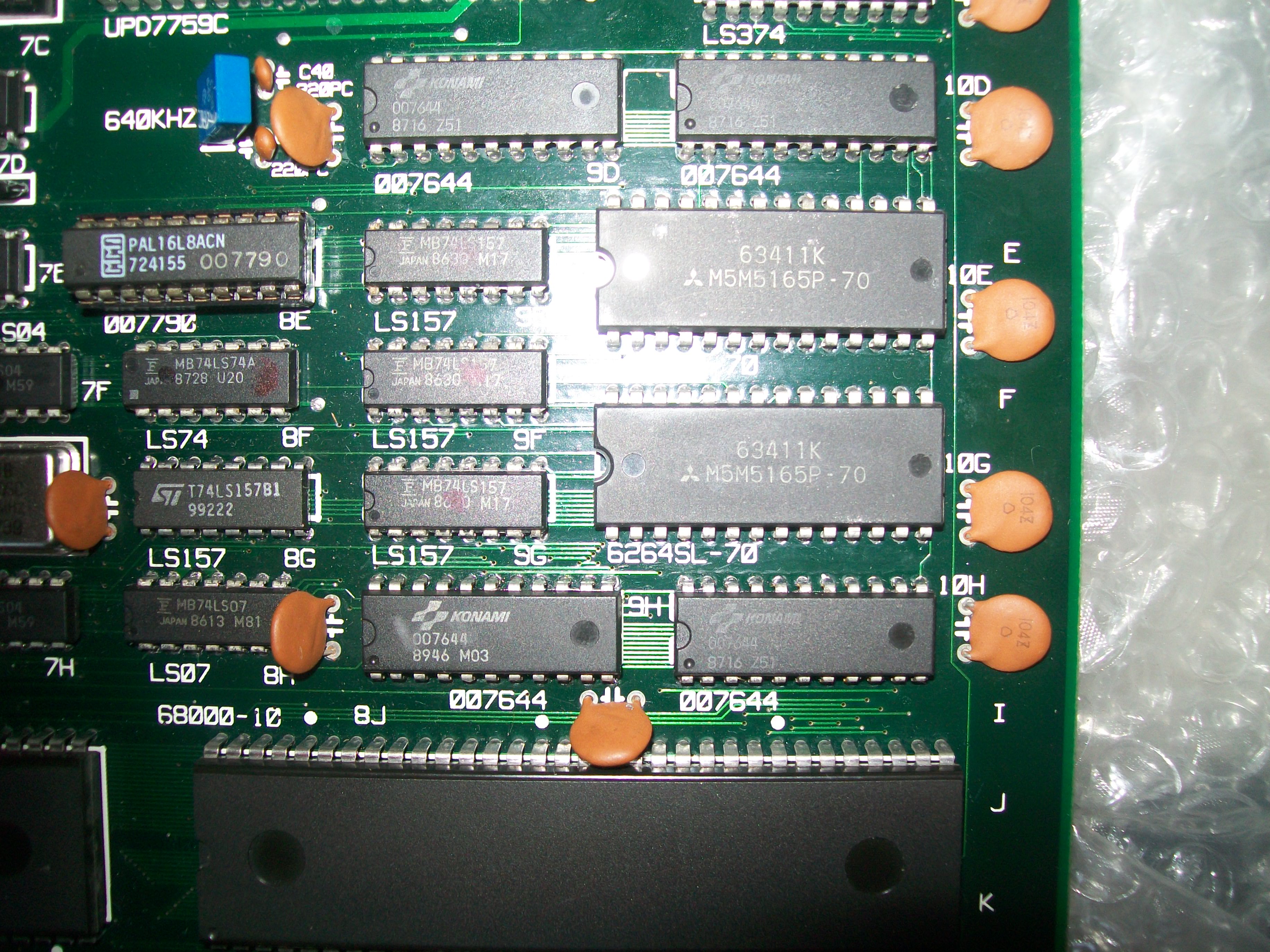
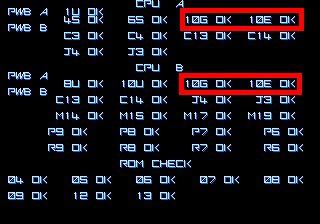
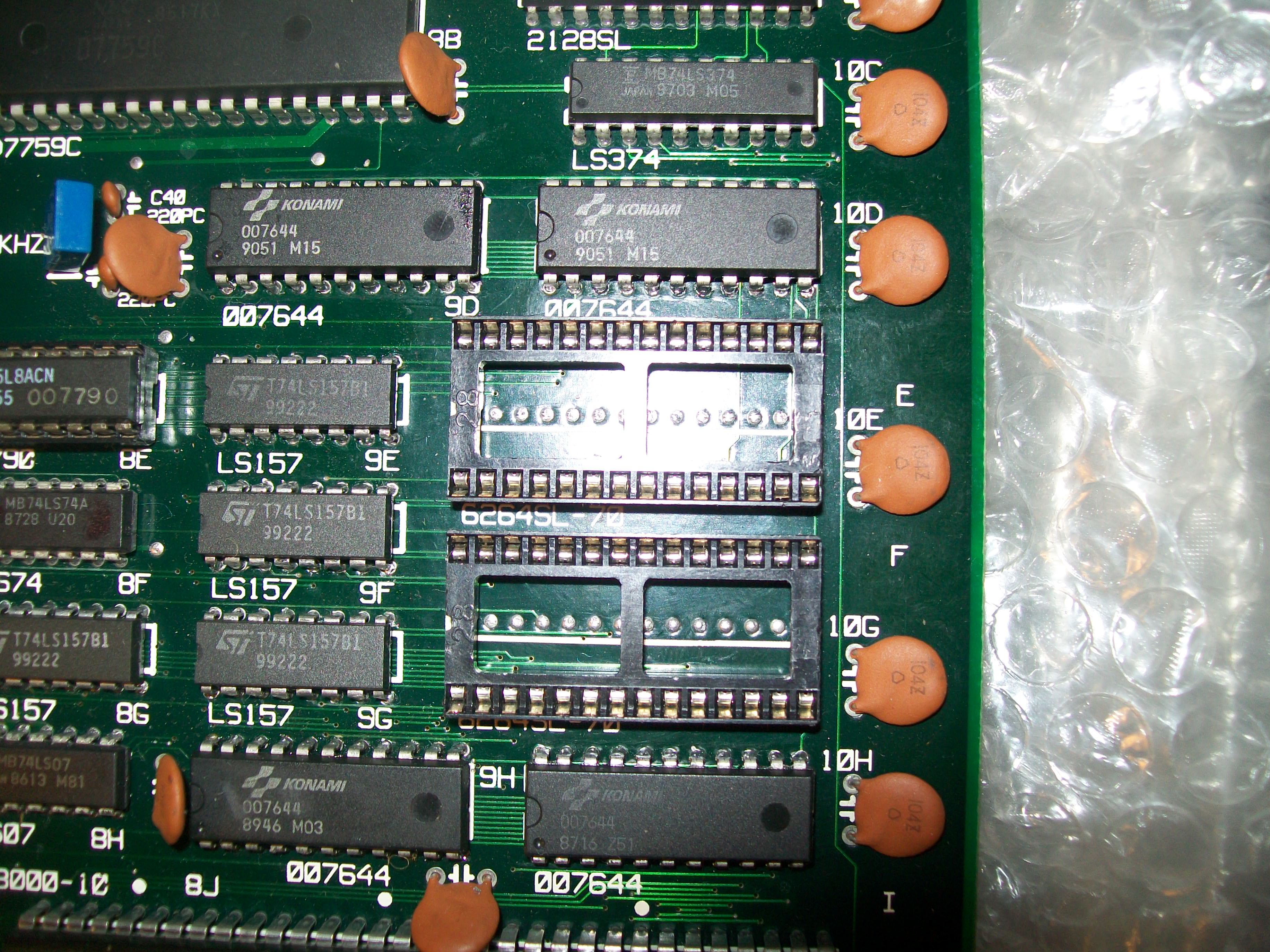
Piggybacking the 64kb RAMs @ 5E, 6E and 9E successfully restored a lot of the backgrounds but there was still some garbled data, even after replacing them.
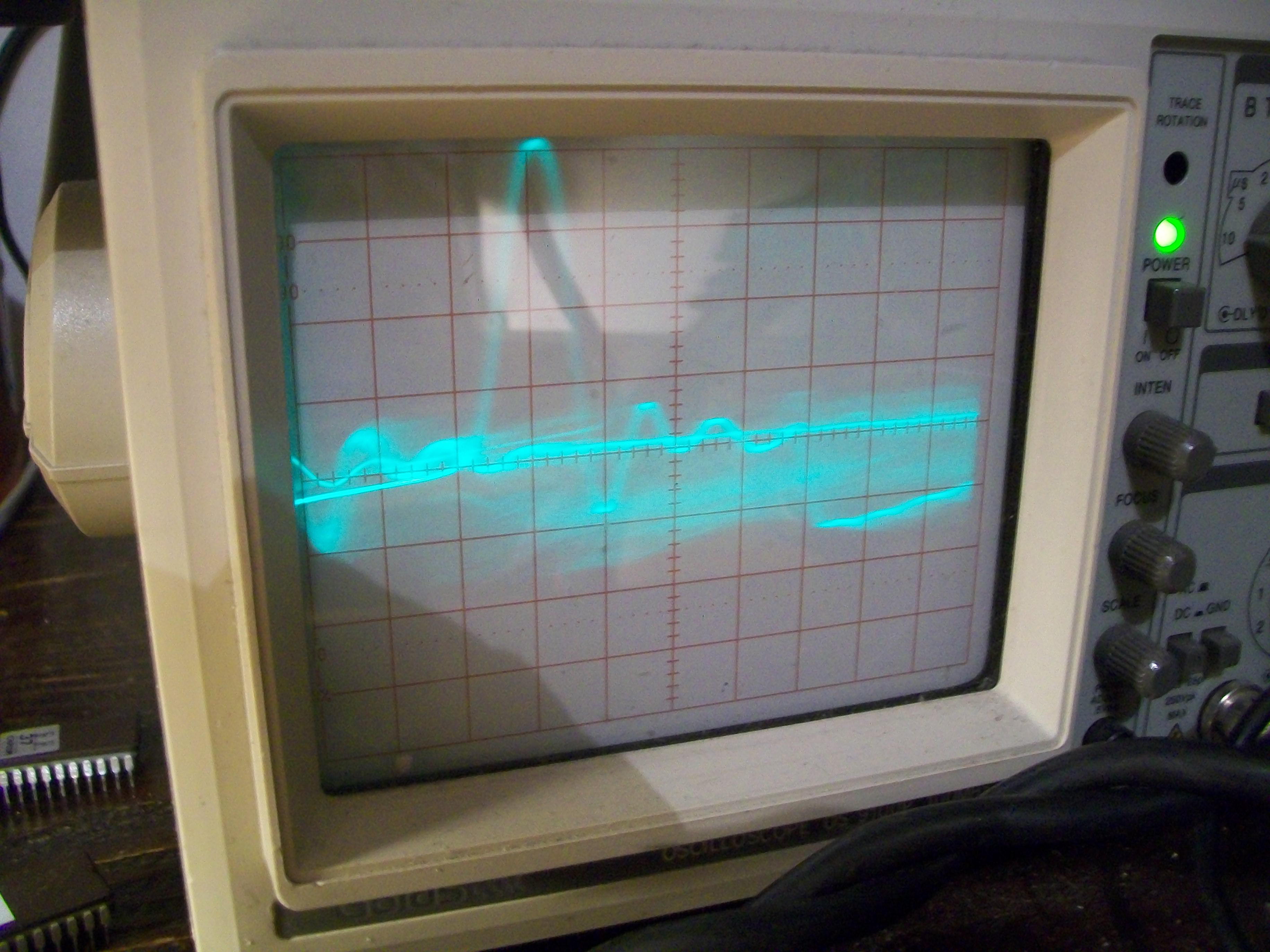
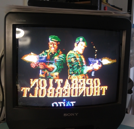
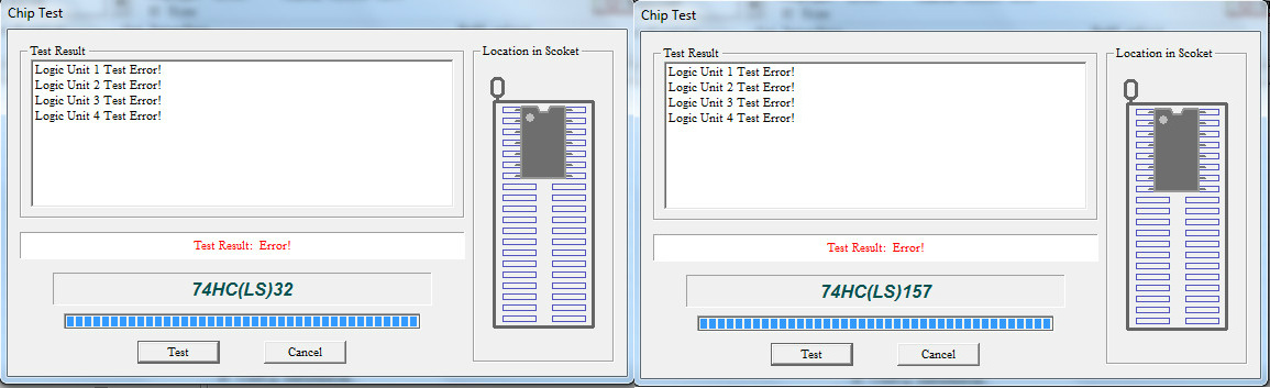
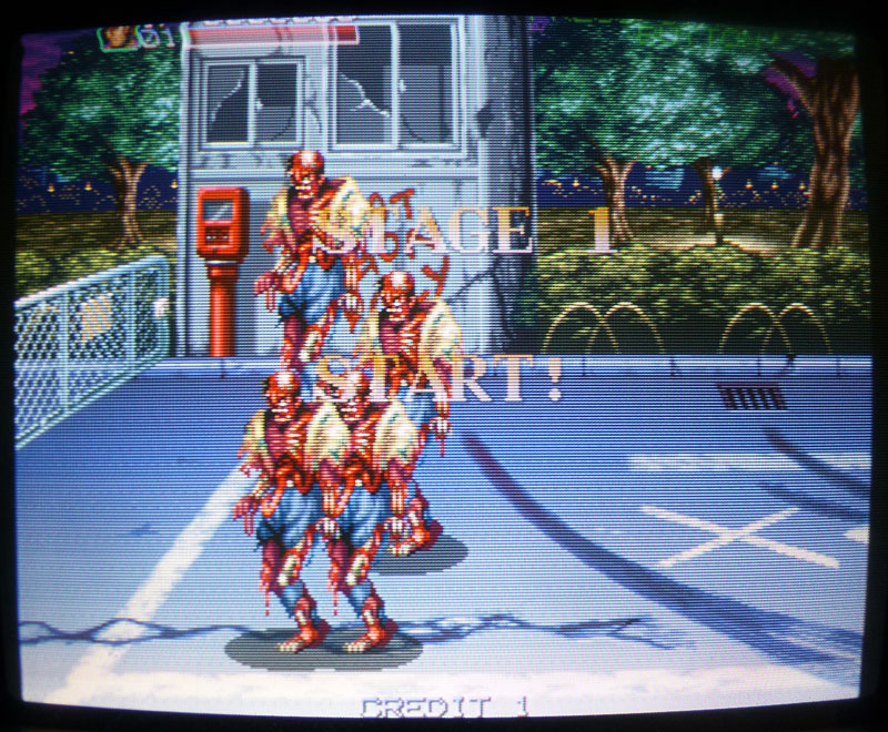
– Problem #2: The fourth RAM @ 10E was tested good, as well as the two MASK ROMs @ 8A and 9A where the background data is stored. Touching the contacts around the gfx area with slightly humected fingers revealed a few ones where data seemed missing/corrupted as we could see the garbled pixels slightly changing. These sensible contacts led to a 74F373 @ 12C, a 74LS373 @ 11C and a Data East ASIC number 74. The signals looked healthy on the scope so after desoldering the two suspicious TTLs chips, it was finally the Motorola 74F373 @ 12C that was faulty. Replacing the chip finally led to a perfectly fine looking game.
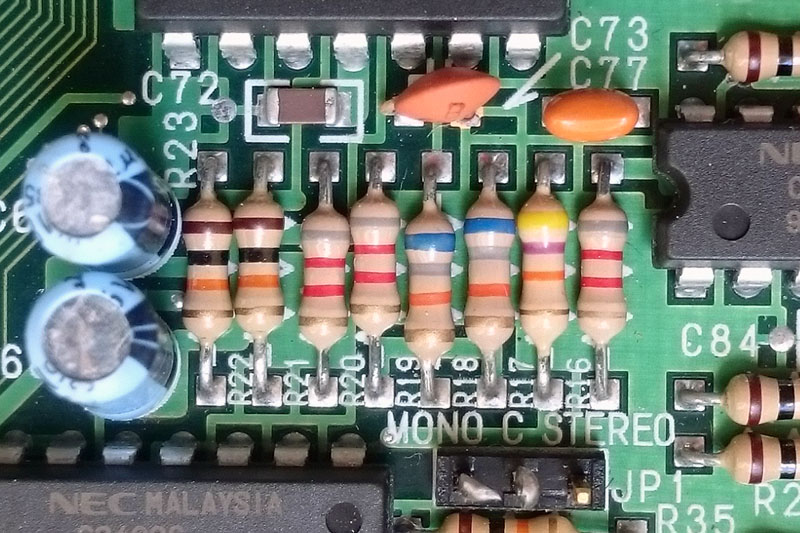
– Problem #3: FM sounds (synths, generated by an YM2151) were very weak compared to sampled sounds (voices, percussions and other samples, generated by two M6295)
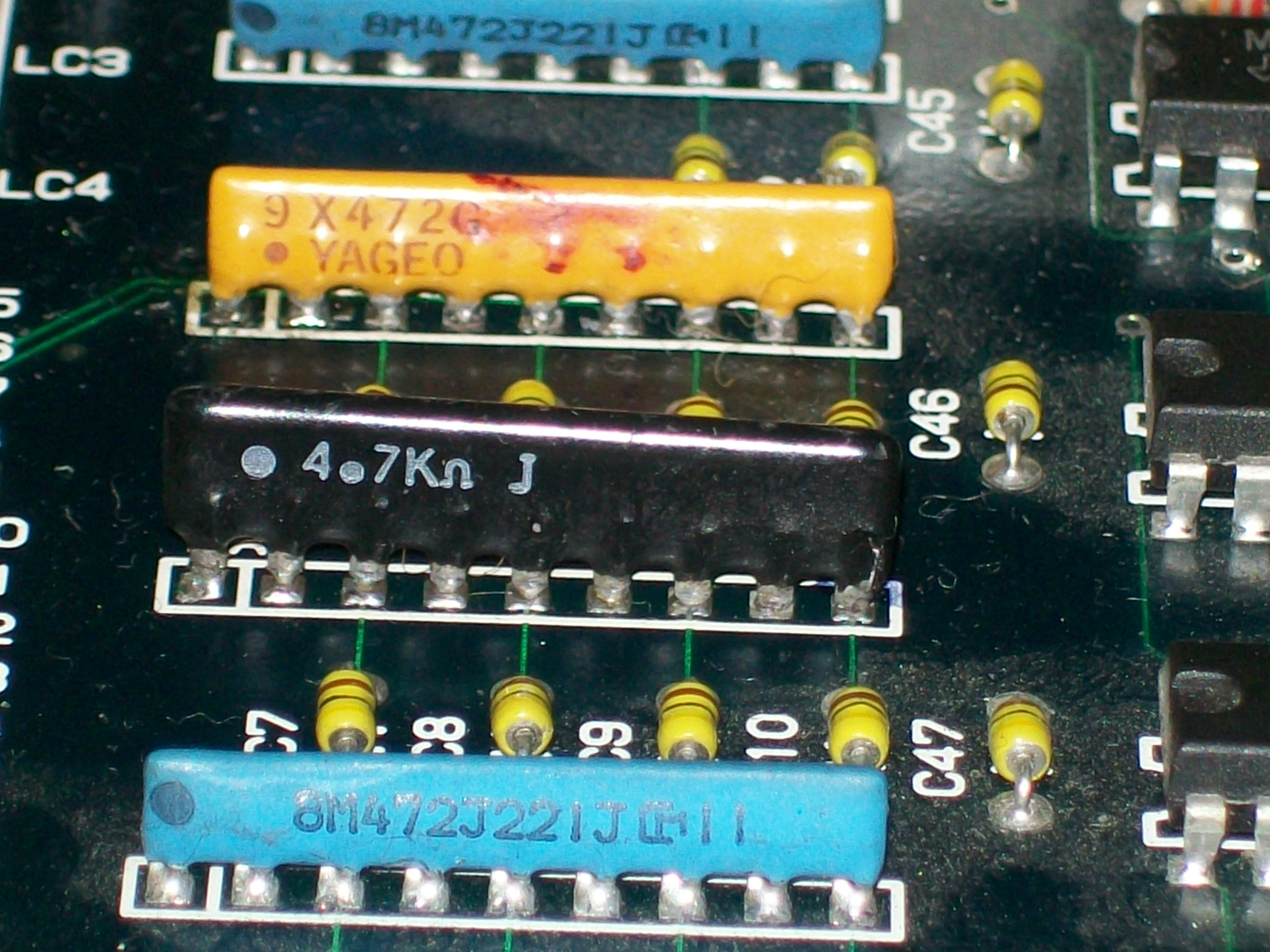
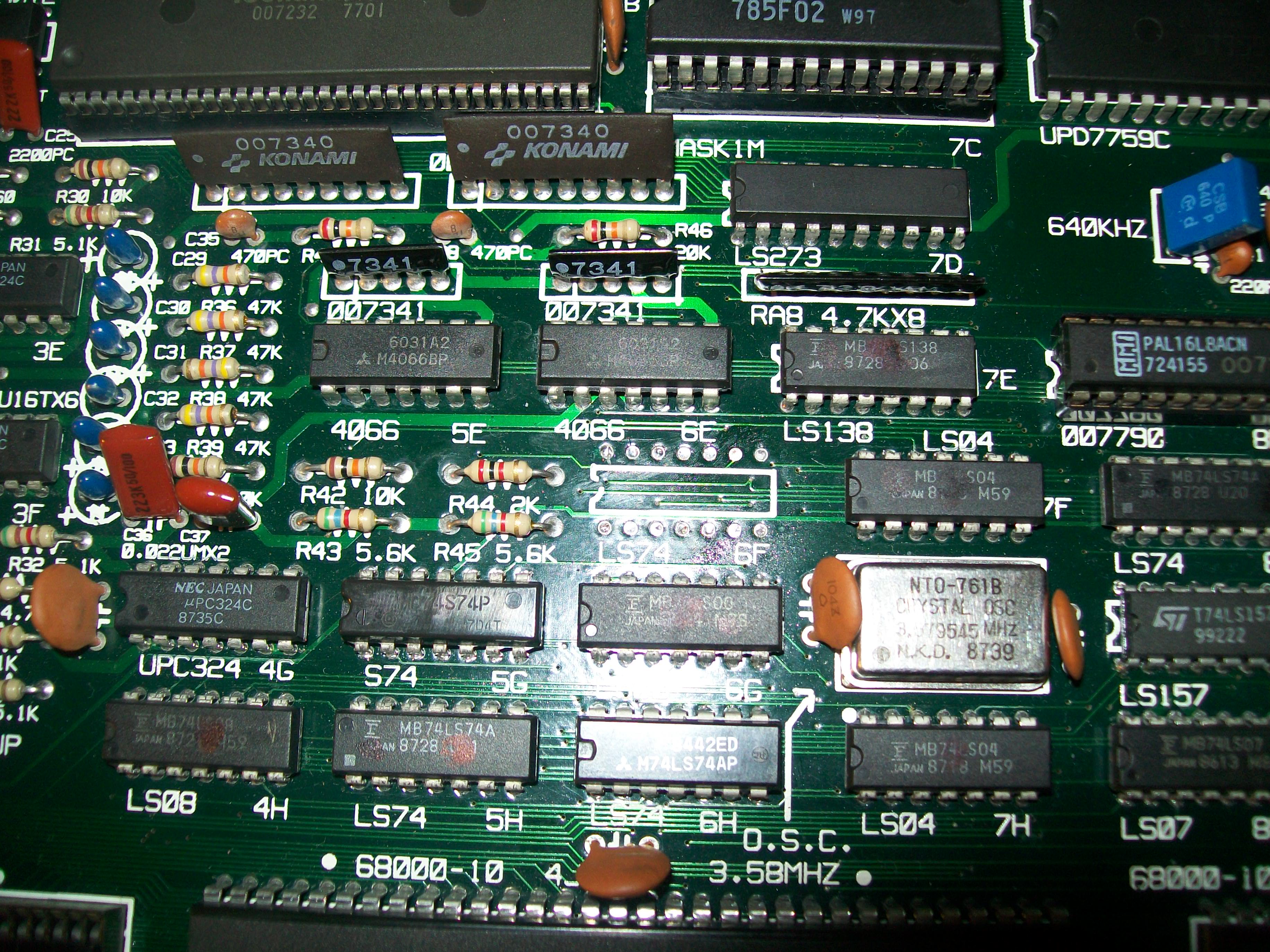
Comparing the audio part with an other board revealed a factory mistake in the row of resistors that connect every sound channel to the amp circuit… They put a 15 kOhm at R17 instead of a 47 kOhm. For a good balanced sound, here are the correct values for them:
-R16, R20 & R21 : 8 kOhm (seen 7,4 kOhm on a DE-0395-1 board revision, difference isn’t perceptible)
-R17 : 47 kOhm (seen 50 kOhm on a DE-0395-1 board revision, difference isn’t perceptible)
-R18 & R19 : 67 kOhm
-R22 & R23 : 10 kOhm
- SECOND FAULTY BOARD (DE-0397-0 revision)
– Problems:
-Game was booting but with some letters staggered.
-Game was crashing along with a vsync issue anytime an ingame screen appeared.
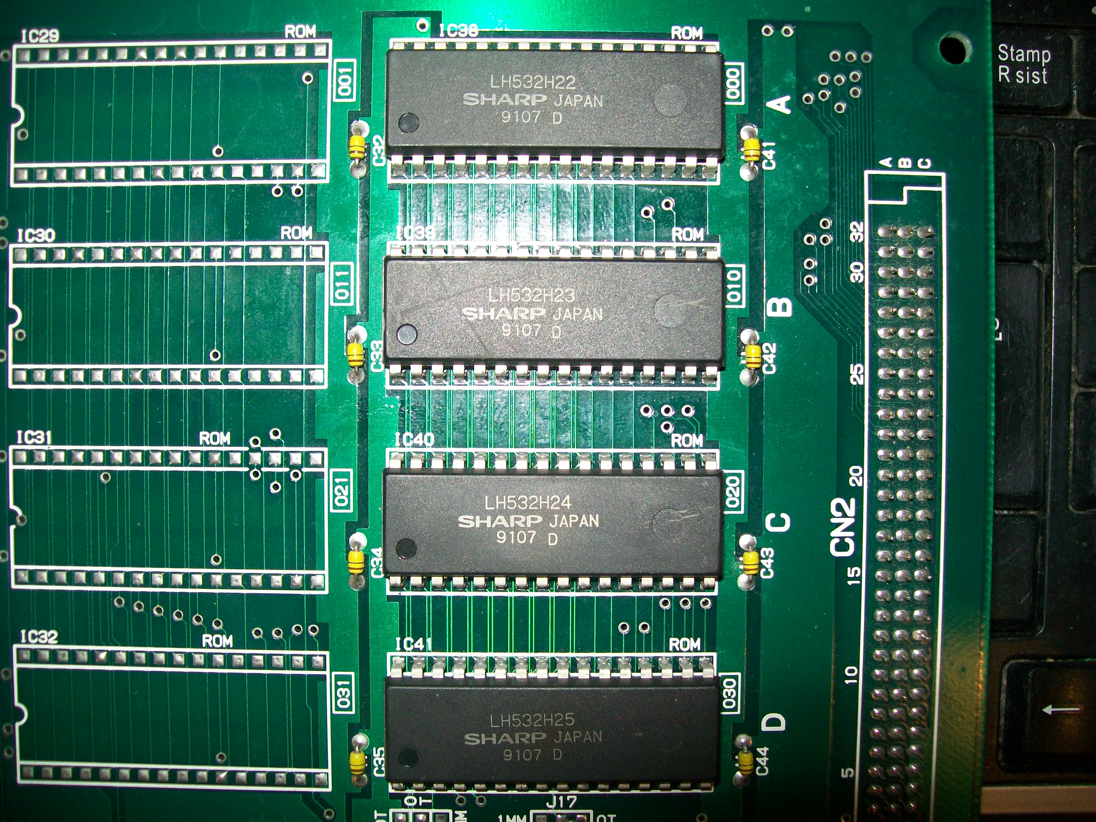
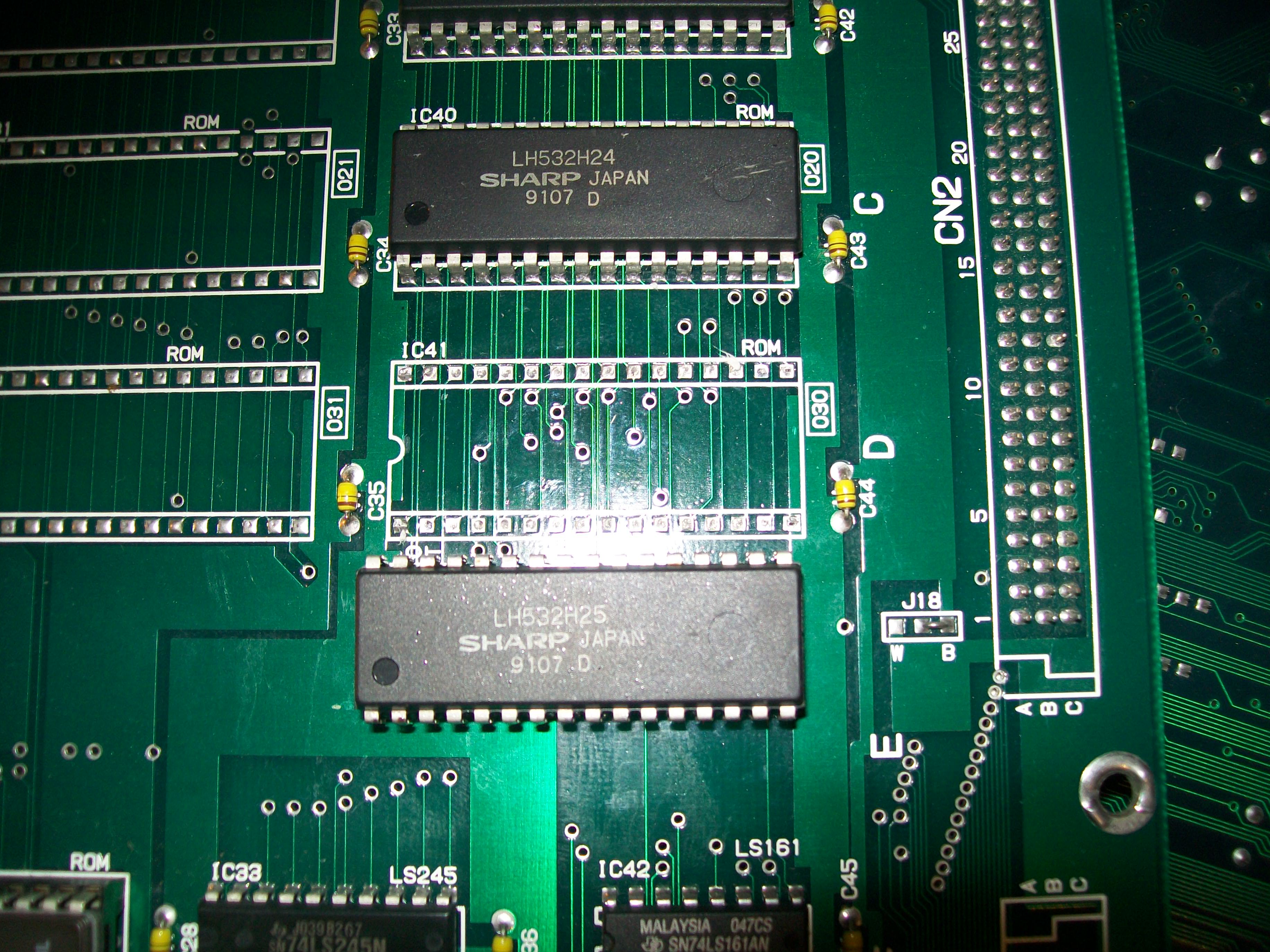
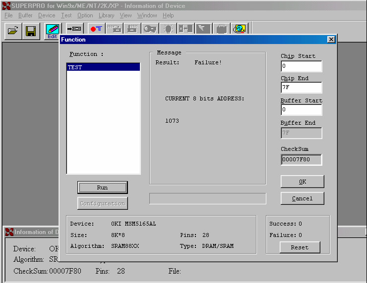
Never had this kind of fault before. The staggered letters could be an issue in the gfx part but the instant crash after an ingame screen was clearly a CPU related issue. Not really easy to diagnose (of course I checked the CPU ROMs and PALs but they were good) so I started focusing on the RAMs, a row of 4 SMC SHARP LH52250. Touching the pins on some of their address lines with humected fingers sometimes changed a few of the staggered letters so I replaced the whole lot of 4 and luckily one of them was the faulty one. Replacing it fixed the letters and crash issues.
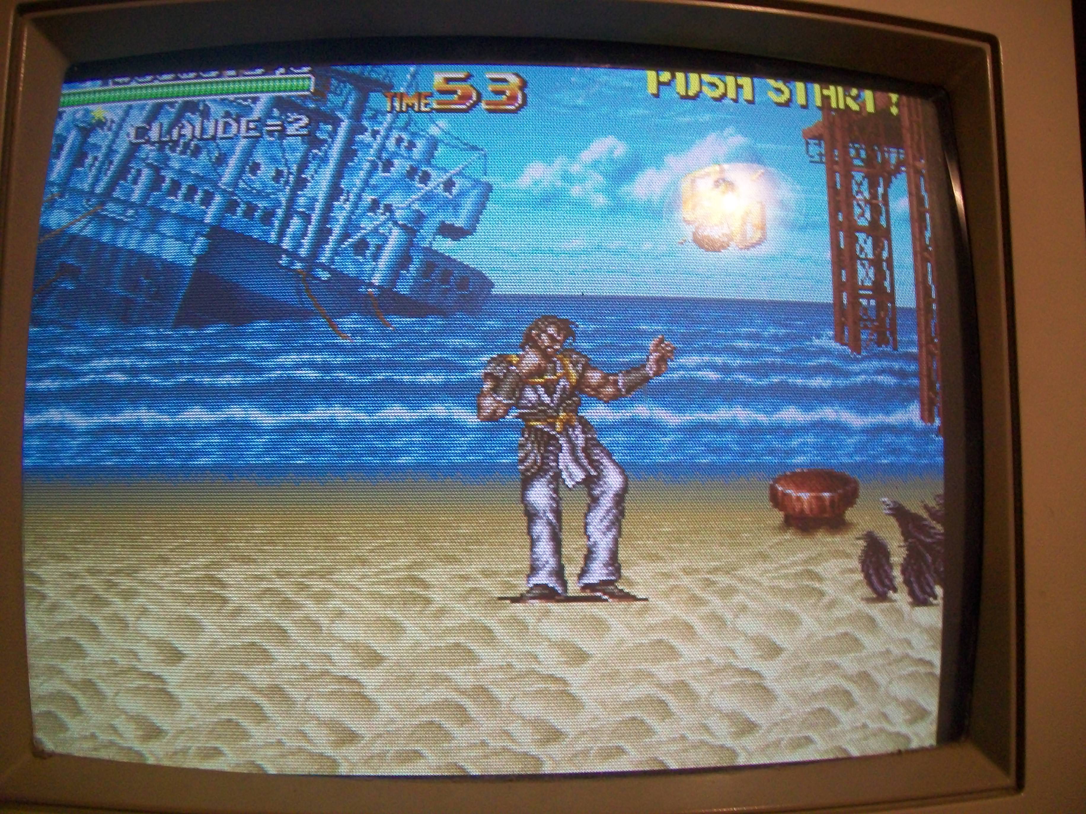
ps. I cannot show pictures of the staggered letters as I forgot to take pictures of the screen before replacing the faulty RAMs. To give an example, the name of the character CHRISTOPHER in the player select screen appeared as CHRISTOGHER.
- THIRD FAULTY BOARD (DE-0395-1 revision)
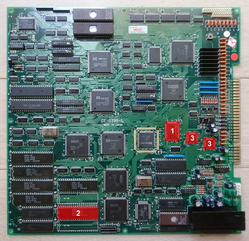
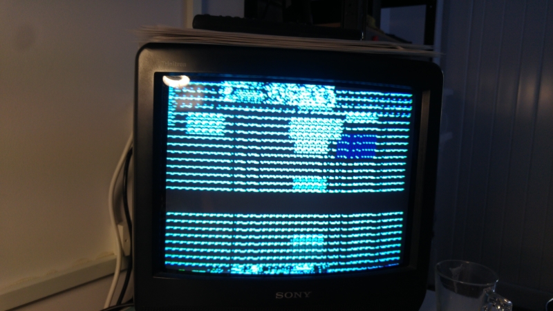
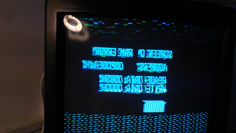
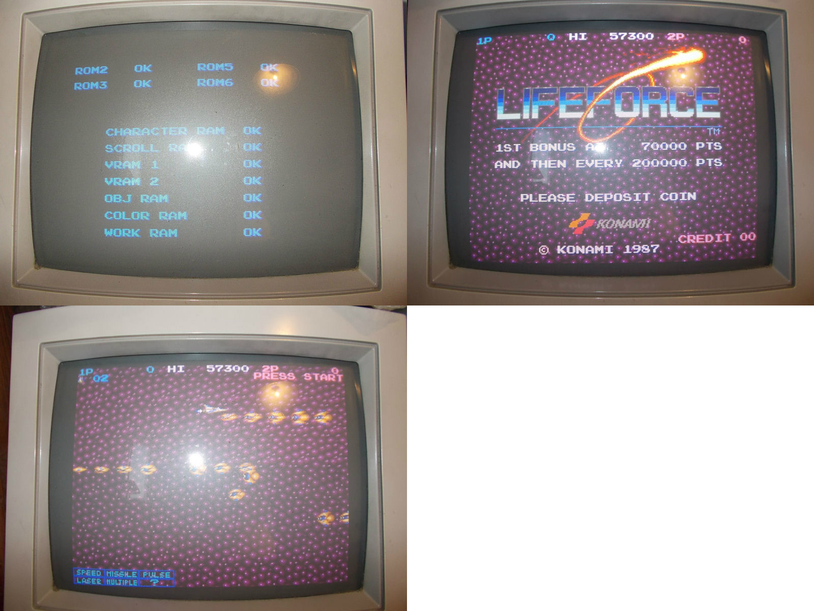
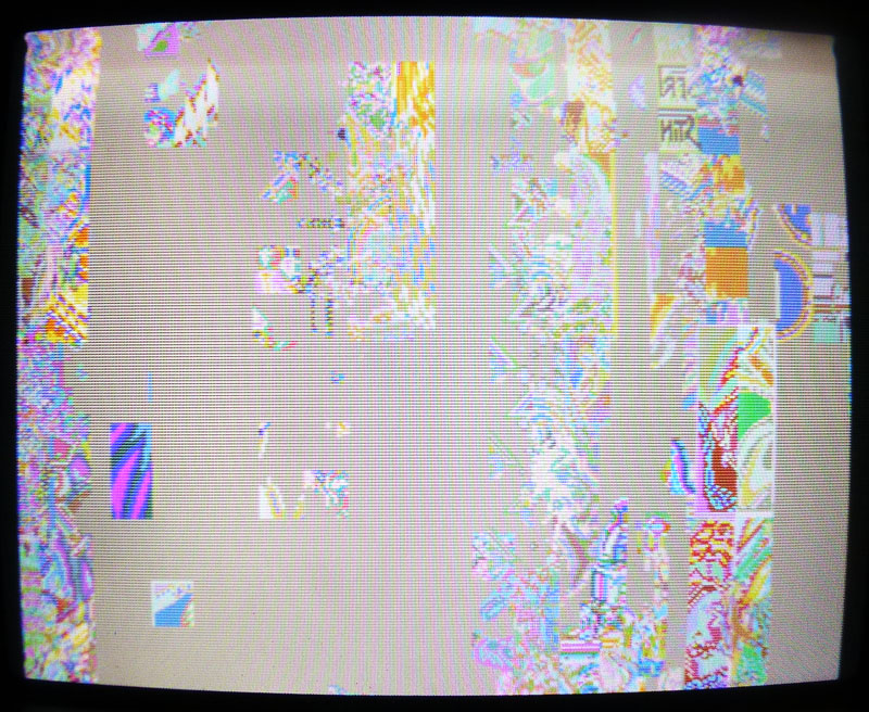
– Problem #1: Board was booting on a garbled screen, randomly with a white or pink background.
This type of issue is due to a problem in the main CPU section. It is a Data East 156 ARM based encrypted CPU and there is not much information online nor pinouts available so diagnosing it is a bit tricky. First, as it worked with the previous board, I replaced the 4 CPU RAMs, but with no change. Also, clock and reset signals around the CPU looked fine with the scope. Then, while probing the pins on the CPU, the game suddenly launched with minor gfx and sound issues but also with half of the controls not responding. I retraced the non working buttons from the JAMMA connector to the I/O custom chip which is a Data East 104. Everything looked fine on the scope. When I turned the power off and on again, I got the same garbled screen but after a few tries touching the CPU pins with the scope, I could sometimes get the game running again (with the same issues) or sometimes a black screen with a message : “CONFIGURATION MODE ERROR”.
All these missing controls caught my attention so I looked closer at this Data East 104 custom I/O chip.
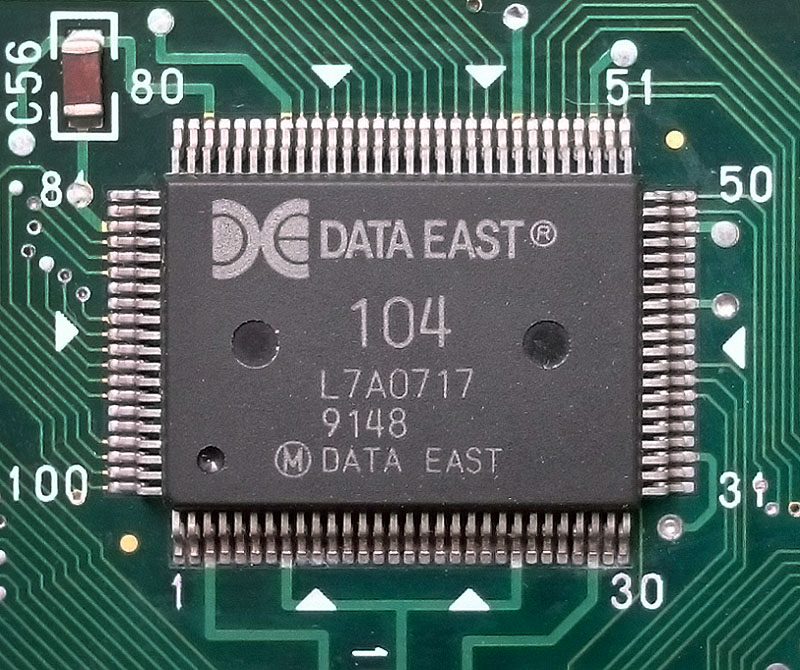
It basically makes the link between every button and the CPU. In fact, it is connected to the data bus and is sending information for all the controls to the CPU. If it is faulty then it could possibly send corrupted data to the CPU which may crash it. For example, that could happen in a lot of Taito boards from the late 80’s, early 90’s: if you plug the JAMMA harness upside/down you plug the 12V signal which normally goes to the audio amp to the controls and it directly damages the I/O custom chip which then send bad data to the CPU, leading to a non booting game.
I reflowed this 104 chip but with no changes so I decided to desolder it. I had a spare Fighters History board running on a DE-0395-1 revision board (same board than this revision of Night Slashers) and at the same location there was a very similar chip with its part number scratched off. I naturally guessed it was the same chip so I put it in place of the 104 on the Night Slashers board. No luck… Even worse than before: I could not have the game starting at all, only the message “CONFIGURATION MODE ERROR” at best.
So I contacted Bryan McPhail, author of the MAME DECO 32 driver and he was pretty sure this version of Fighters History used a previous revision of the I/O chip numbered 75, not 104. That would explain not having the game booting even once with it plugged in. So I desoldered it and put in place a 104 chip taken from one of the working Night Slashers boards as I needed to clarify the situation… And that time the game launched directly ! I also got all the controls working perfectly.
Good find, but now I had only one 104 working chip for two Night Slashers boards. Bryan told me every 104 chip could work as a replacement. This chip is present on these games: Caveman Ninja, Wizard Fire, Rohga, Boogie Wings, Diet Go Go, Double Wings, Schmeiser Robo, Pocket Gal DX and Dream Ball. The two last ones being the only ones I could imagine being donor boards, I put my hands on a Pocket Gal DX board, took the 104 chip out of it to put on my Night Slashers board then got it running with all the controls ok.
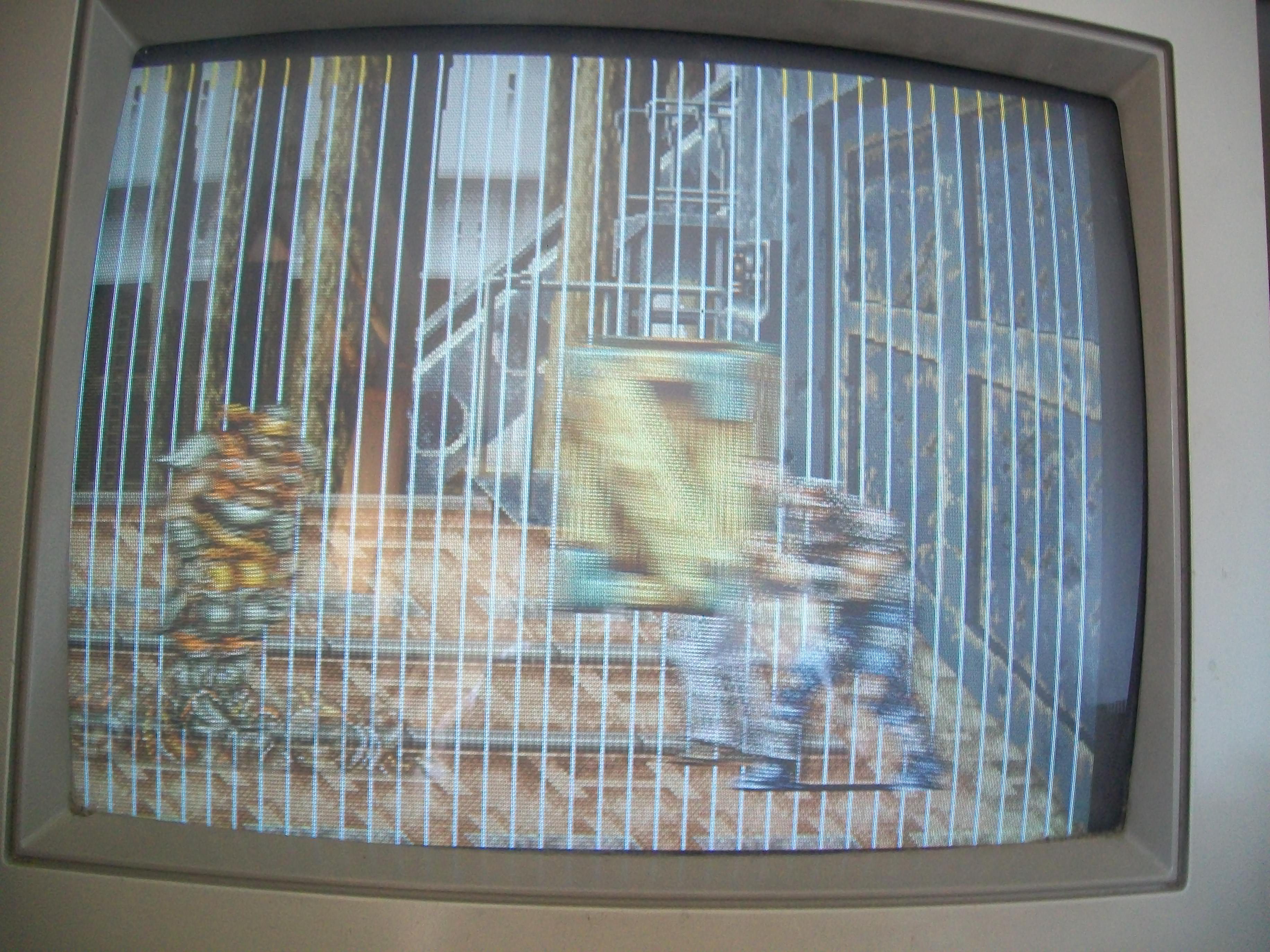
– Problem #2: Had a few gfx issues (vertical lines on a few sprites).

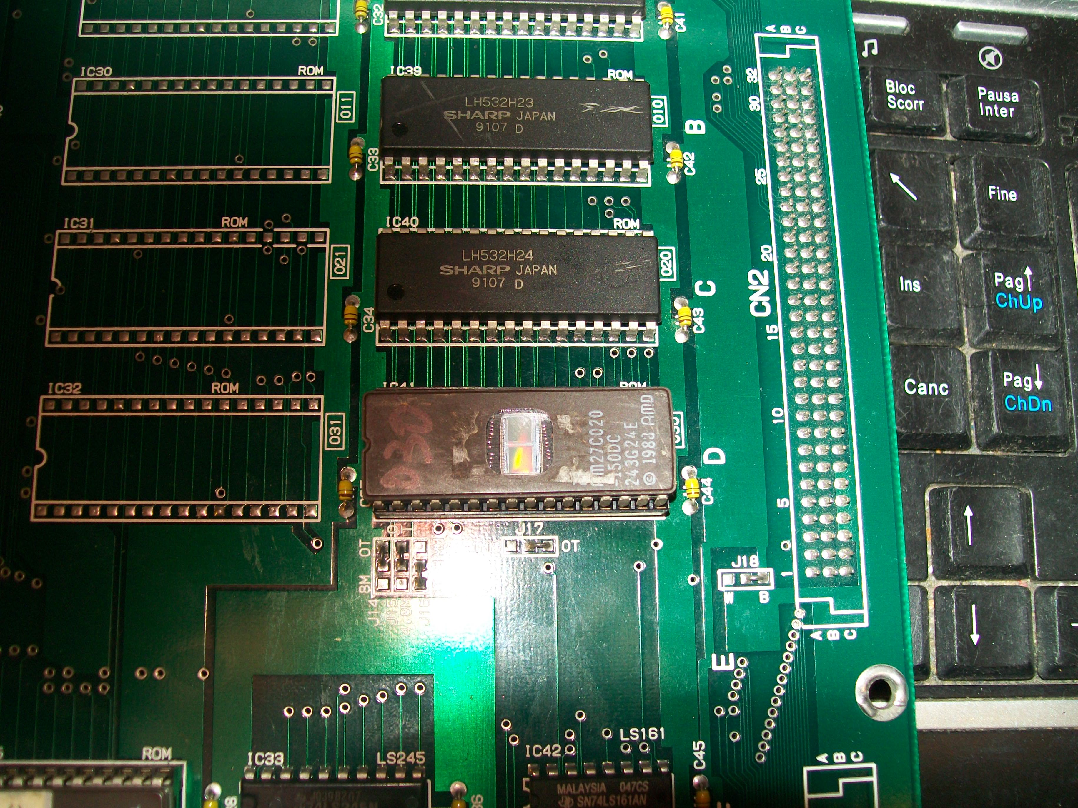
I quickly found something by touching pins on the gfx ROMs. Vertical lines seemed partially flickering and disappearing when touching some of the address lines on the MASK ROM labeled MBH-09. These are 512kb ROMs with MASK pinout so I burned the matching content on a 27C400 EPROM and tried piggybacking it. It resolved the problem so I put a socket and plugged it as replacement.
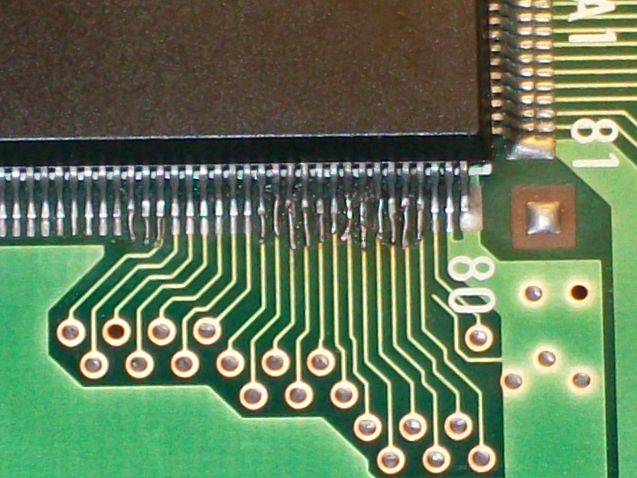
– Problem #3: Had some sounds issues. Some voices/samples were missing and replaced by junk noise. One of the two M6295 voice generating chips @ 12M had previously been badly repaired and a pin was very near to fracture. Tracks #14 & #18 on the board were broken by the previous repairer and replaced by two wires going from the M6295 to the MASK ROM @ 14L. I removed the serviced chip and these two wires. In order to replace the missing tracks, I inserted tiny pieces of wire in the holes below the chip, bended them and soldered them in.
You can see here how they were broken on track #14 and how I fixed them on track #18:
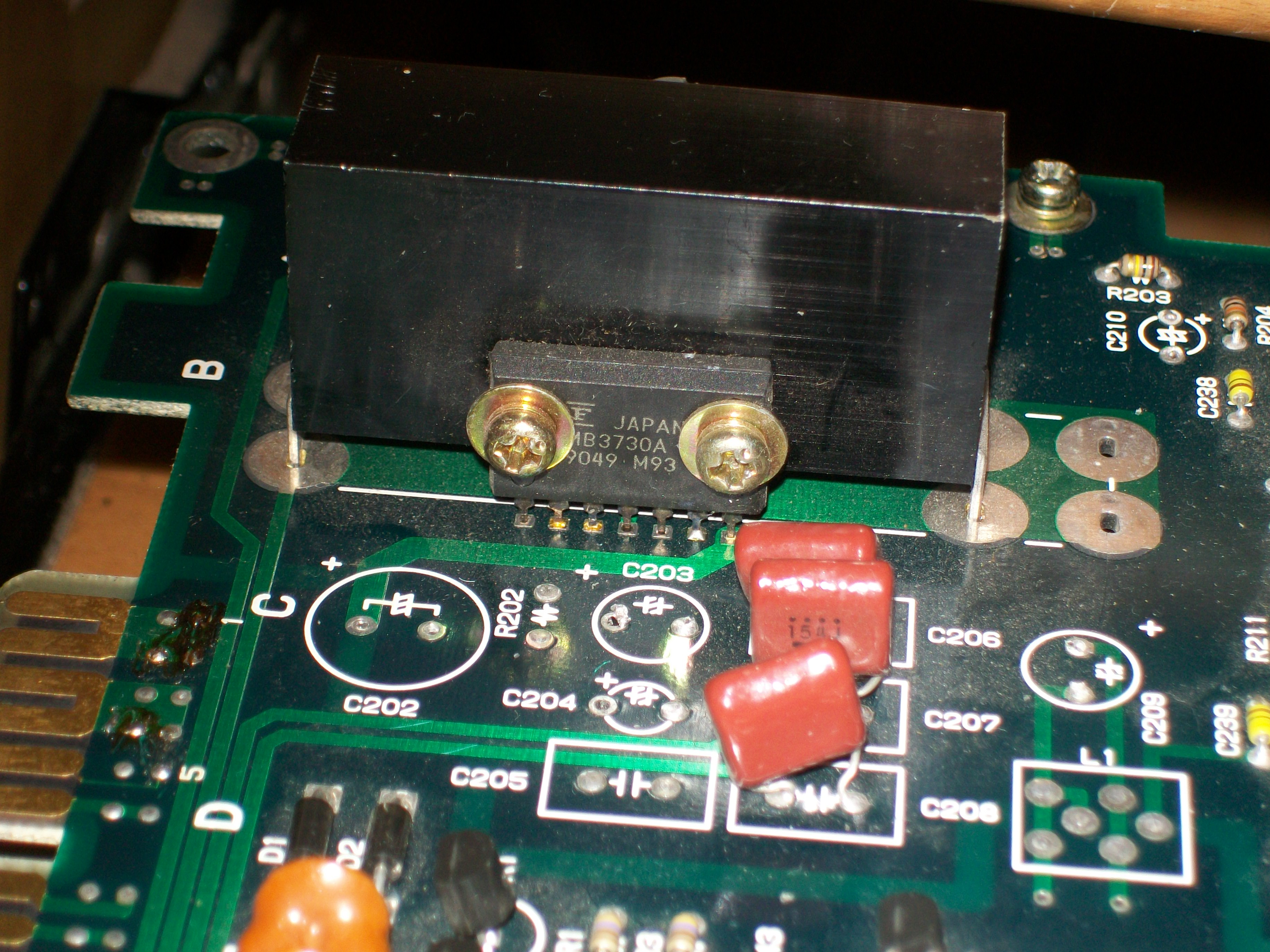
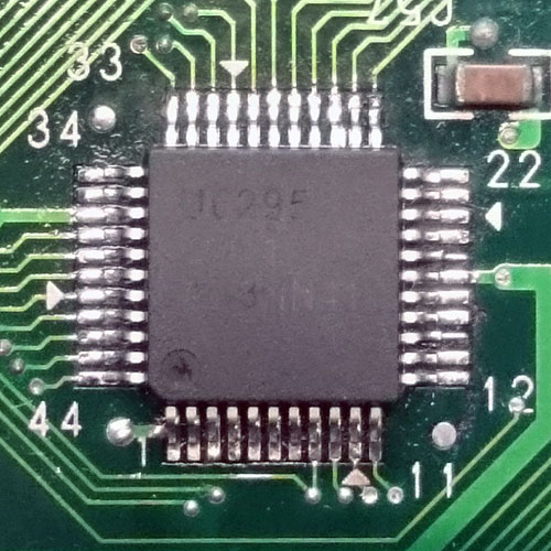
And here is how it looks after a new chip in place:
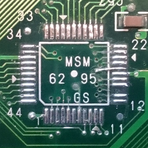
Part of the voices were back but some junk sounds were still audible. While checking the other M6295 chip @ 13N, I found a signal that seemed strangely inactive on an address line which goes to the MASK ROM @ 15L where these sounds are stored. I piggybacked the ROM with a burnt EPROM of the same content but nothing changed. Suspected the OKI M6295 so I replaced it and that fixed the issue. Everything is fine now.
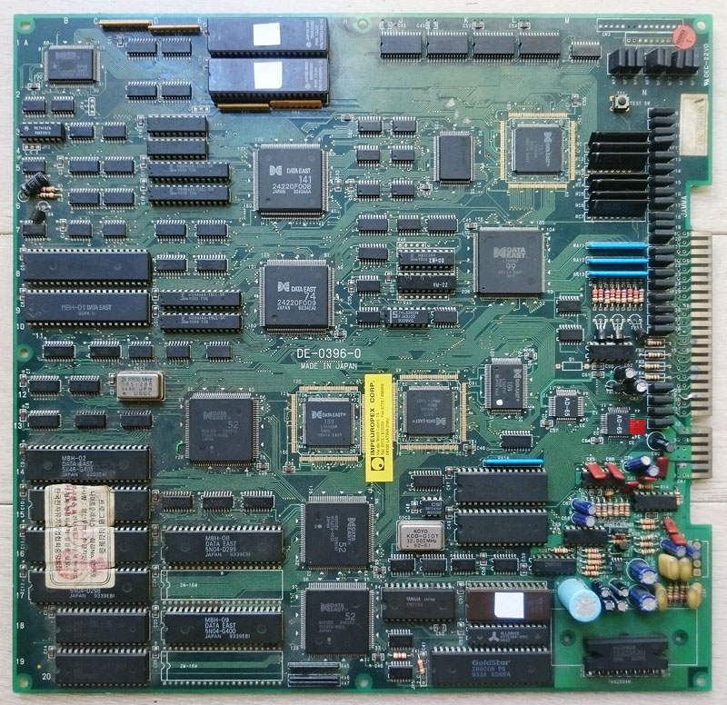
- FOURTH FAULTY BOARD (DE-0396-0 revision)
– Problem: Had some sounds issues. Some voices could be heard repeatedly at unintended moments. For example Christopher was saying “I take that !” repeatedly and randomly.
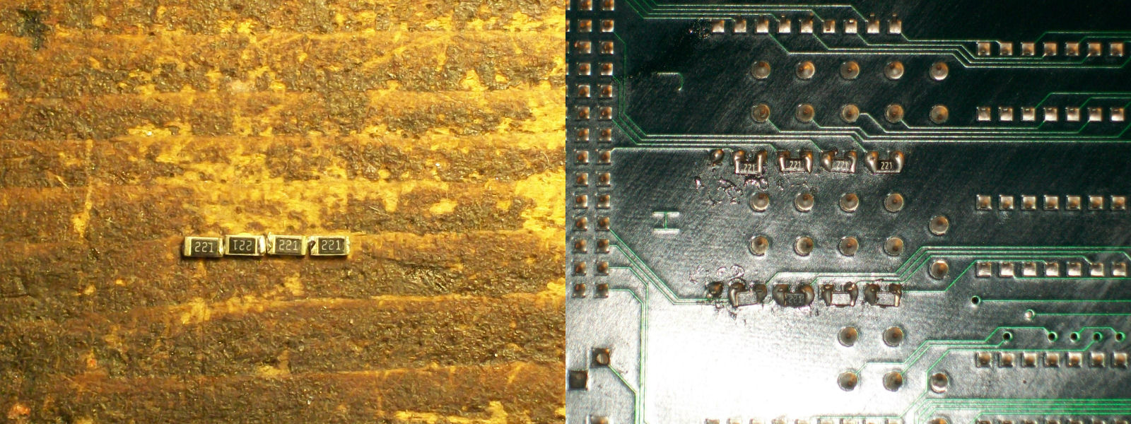
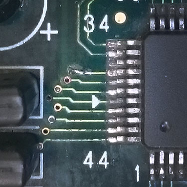
Found an I/O line on the M6295 @ 13N (pin #37) with no activity. This goes to the 104 chip but here there was no continuity with were it is supposed to go. There was a bit of corrosion around the M6295 and a closer inspection of the area revealed a broken hole connected to the track of pin #37:
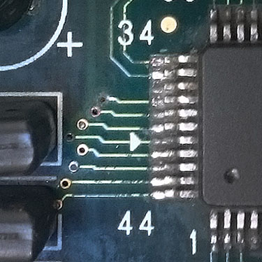
Only this side of the hole was damaged so I inserted a tiny piece of wire on the other side, bended it here and soldered both sides:
That worked. No unwanted voices constantly repeating anymore.