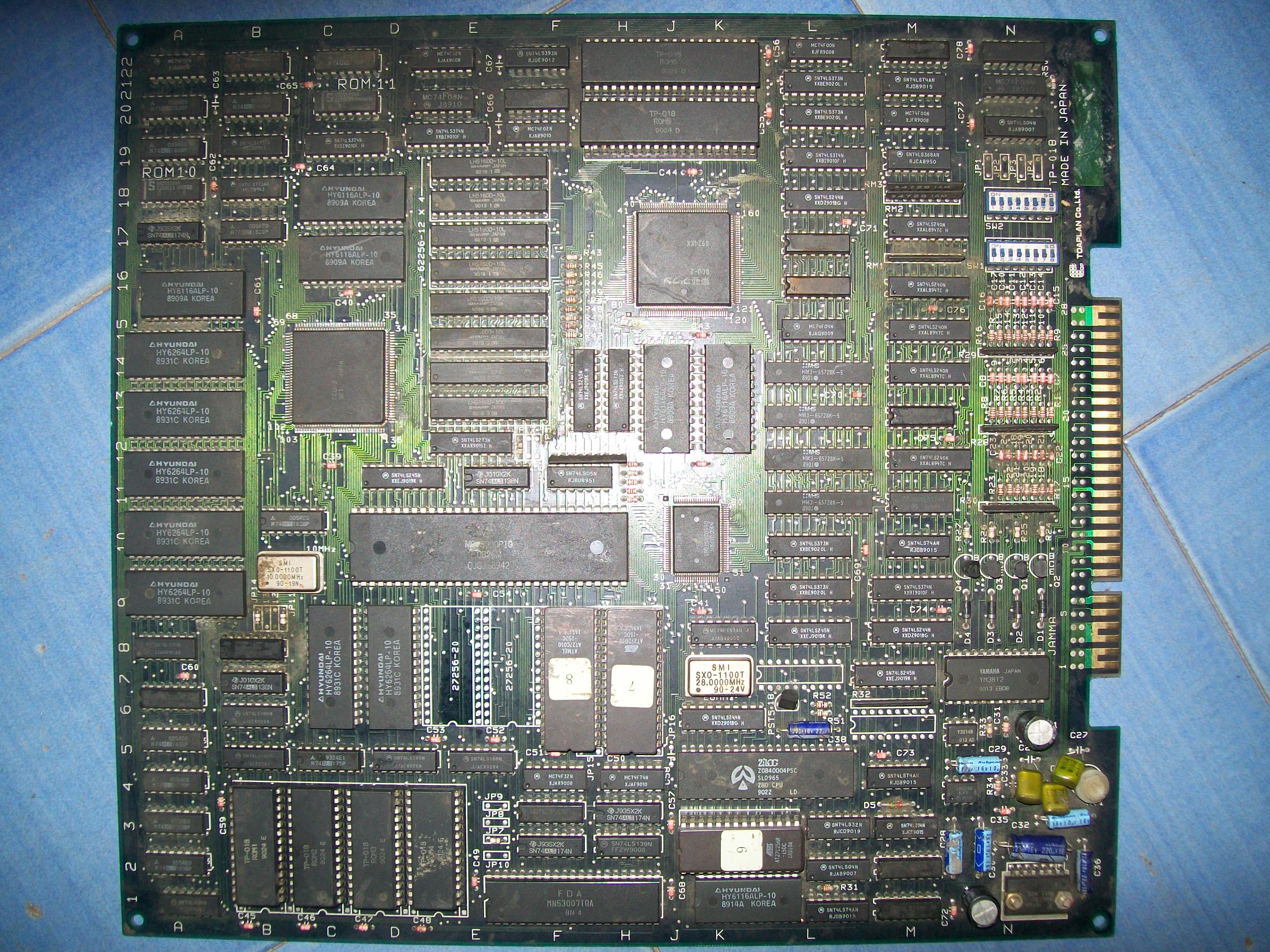
Another Out Zone on the bench and with this one we have five repair logs of this PCB.
Board came in not so great condition, quite dirty :
Like all the Out Zone I have troubleshooted, also this PCB suffered from sprites issue, they were garbled and misplaced :
Having a good knowledge of this hardware, I went to probe the involved circuit.All was fine until my logic comparator reported issue on a couple of outputs of a 74ALS163 @17B:
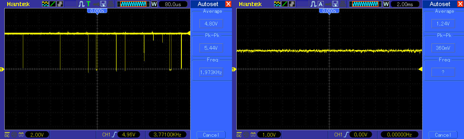
The scope confirmed the outputs were floating compared to inputs:
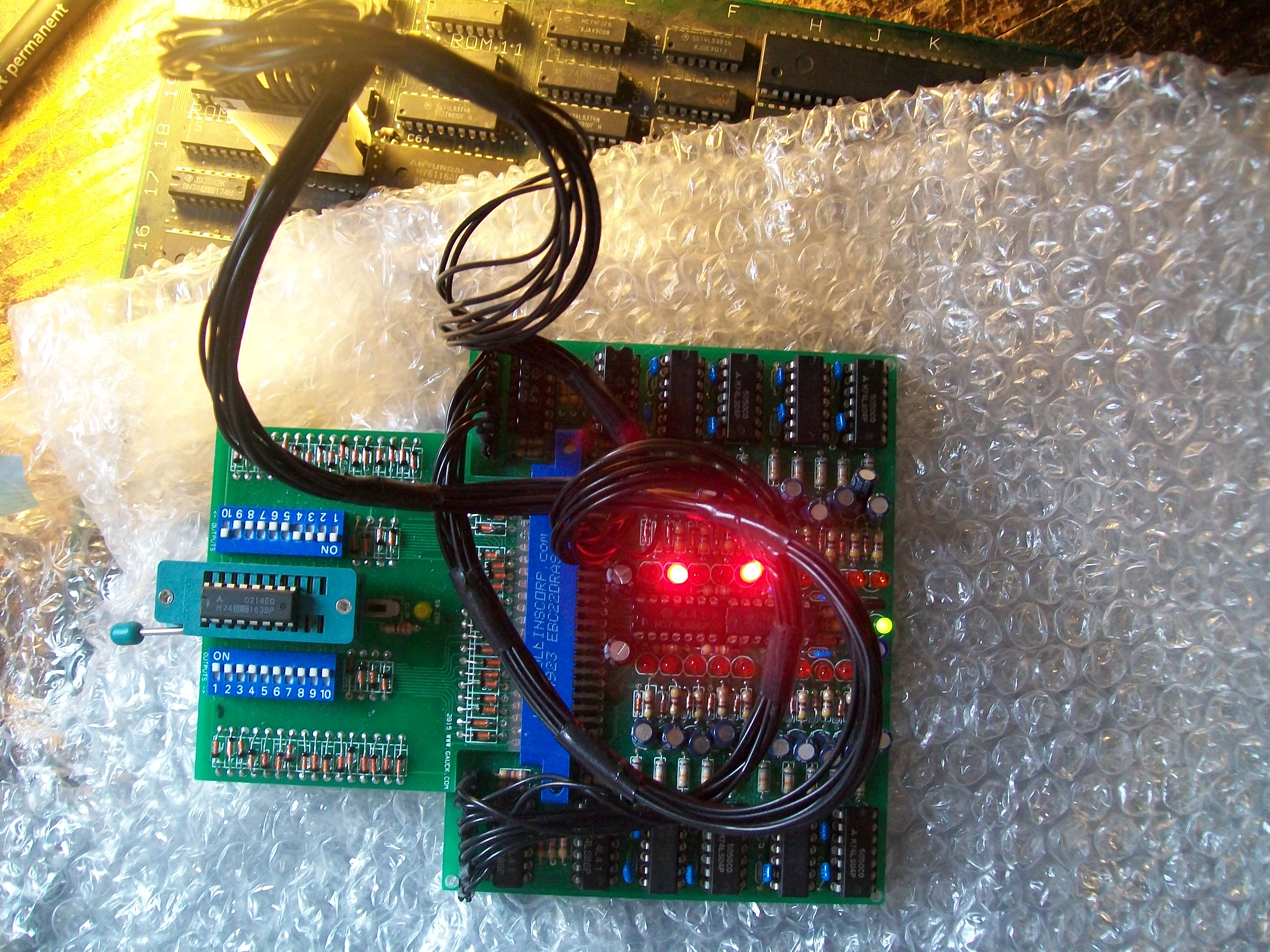
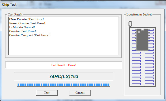
I removed the IC and the out-of-circuit testing failed miserably:
Another Out Zone saved.See you at the next repair of this great game by Toaplan!
PCB Repair LogsComments Off on P.O.W. – Prisoners of War repair log
Sep292016
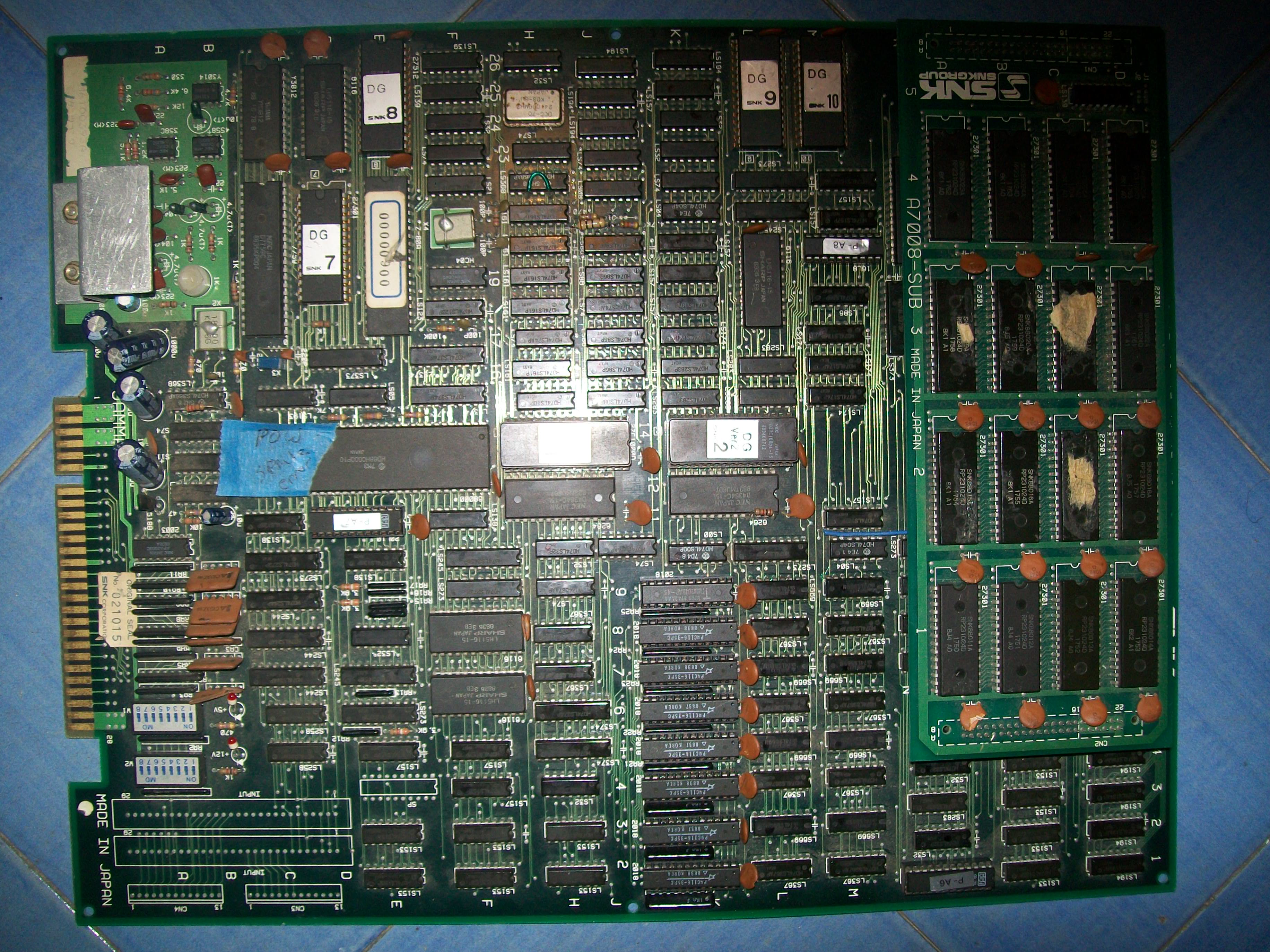
Got this P.O.W. – Prisoners of War PCB since a long time, bought in a lot of faulty boards from USA :
Board was marked by a piece of tape with the words “SPRITE ERROR”.When I first powered the board up, picture could not sync properly on the Philips CM883-II monitor of my supergun (but it did on my Astro City):
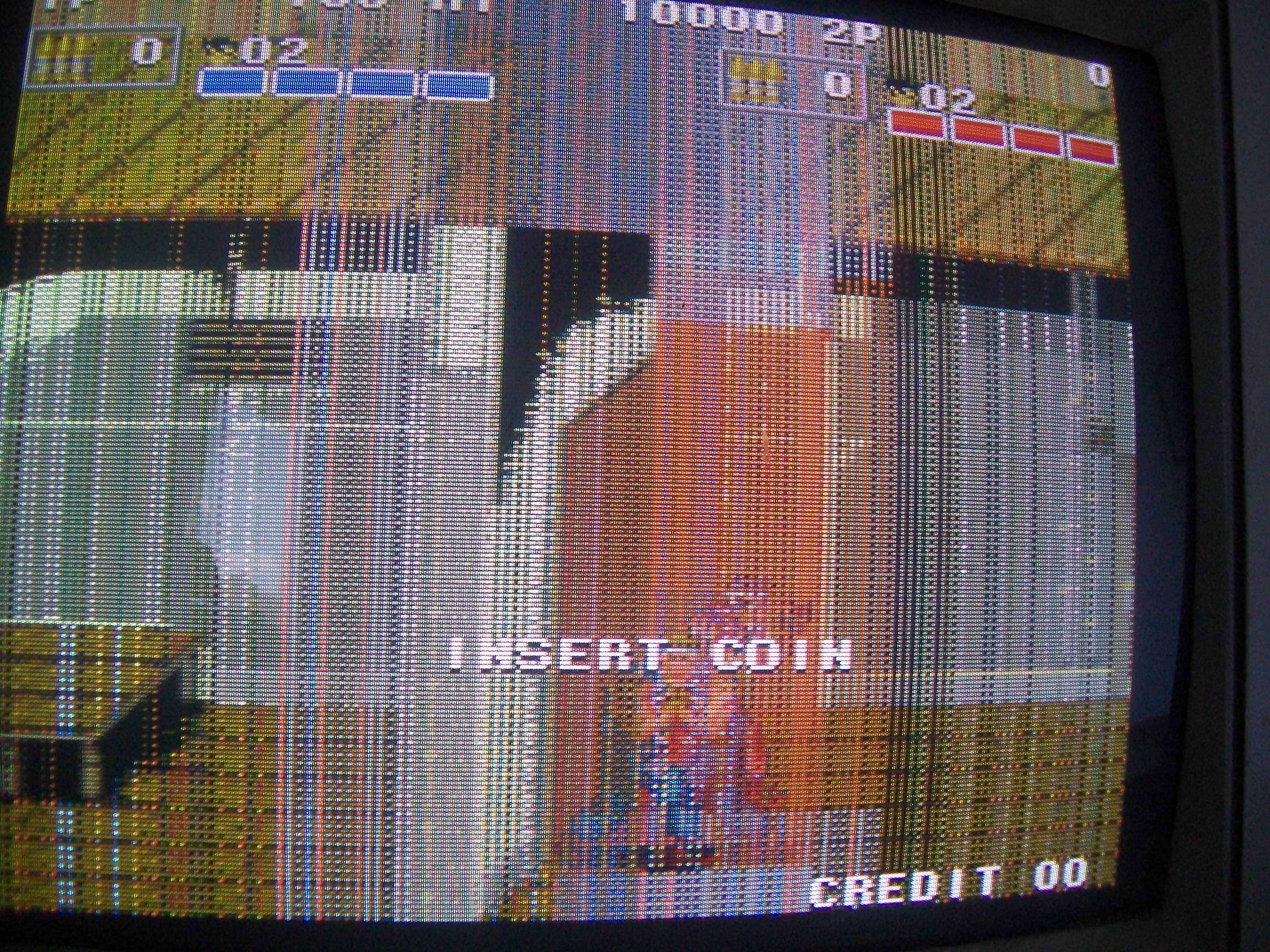
I found a workaround by replacing the 100 Ohm resistor connected in series with the SYNC pin of edge connector with a 10 Ohm one.So the sprite error materialized :
As usual I did my visual inspection and found a severed trace on the solderside (involved in the sprites RAM data bus).Patching it cleared the error so game finally booted showing this issue :
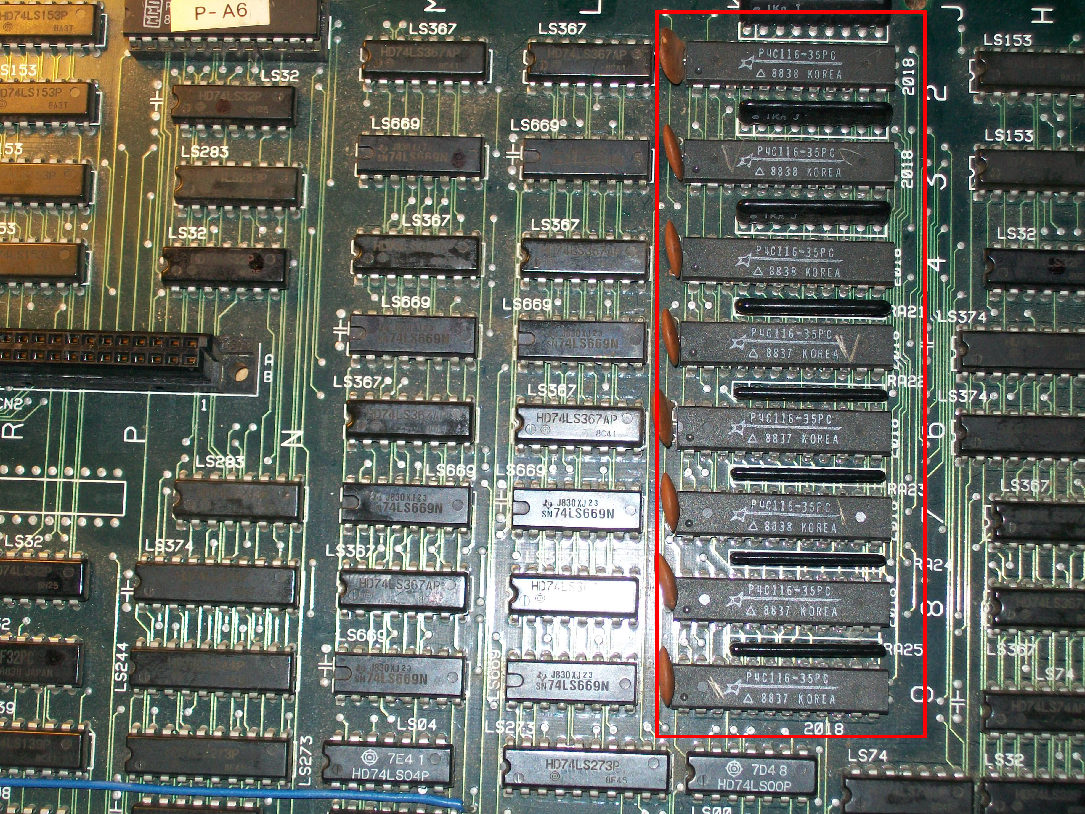
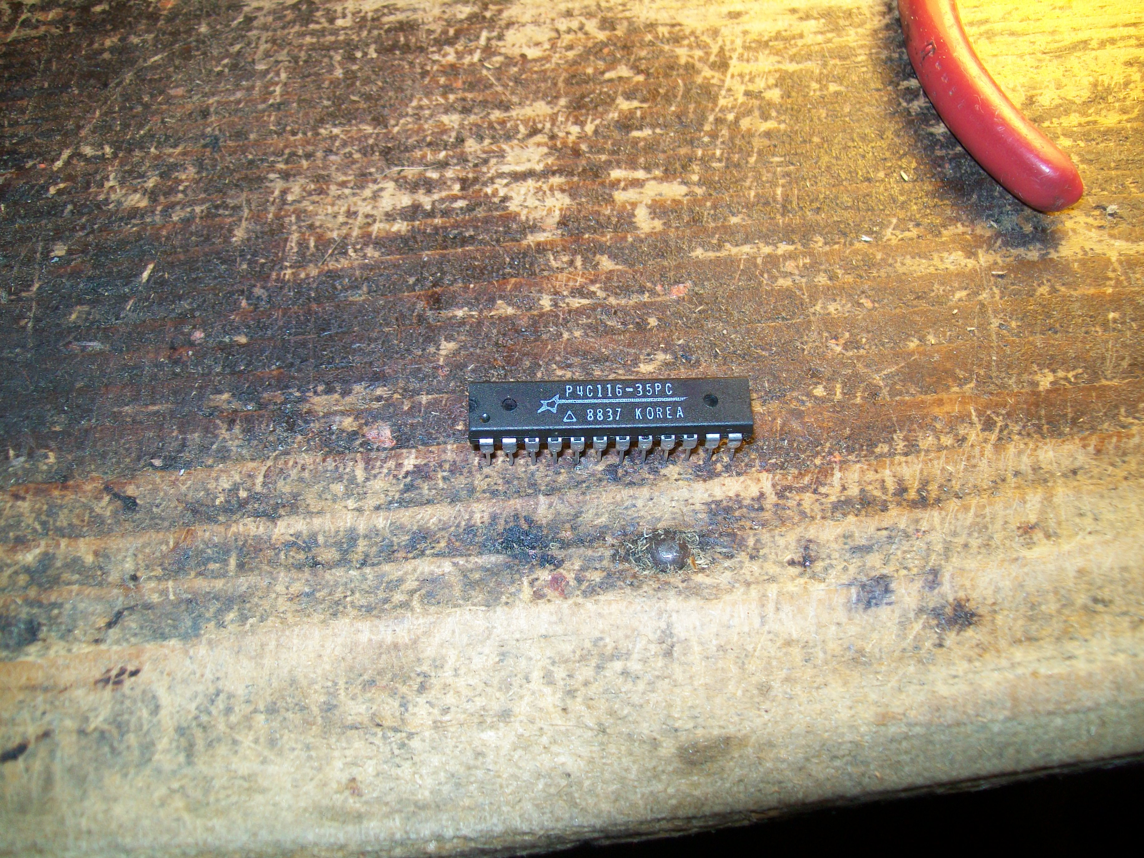
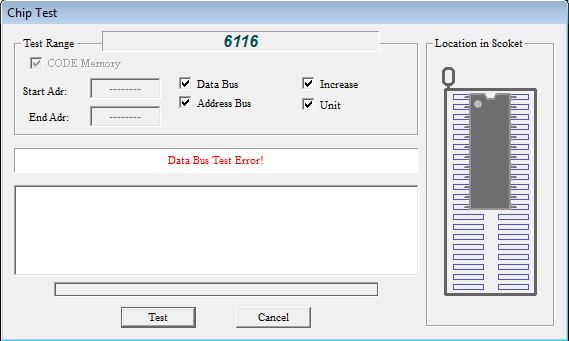
I noticed that if I shorted some address/data lines of a row of eight 2018 RAMs, further lines were displayed so this was the part of circuit involved.
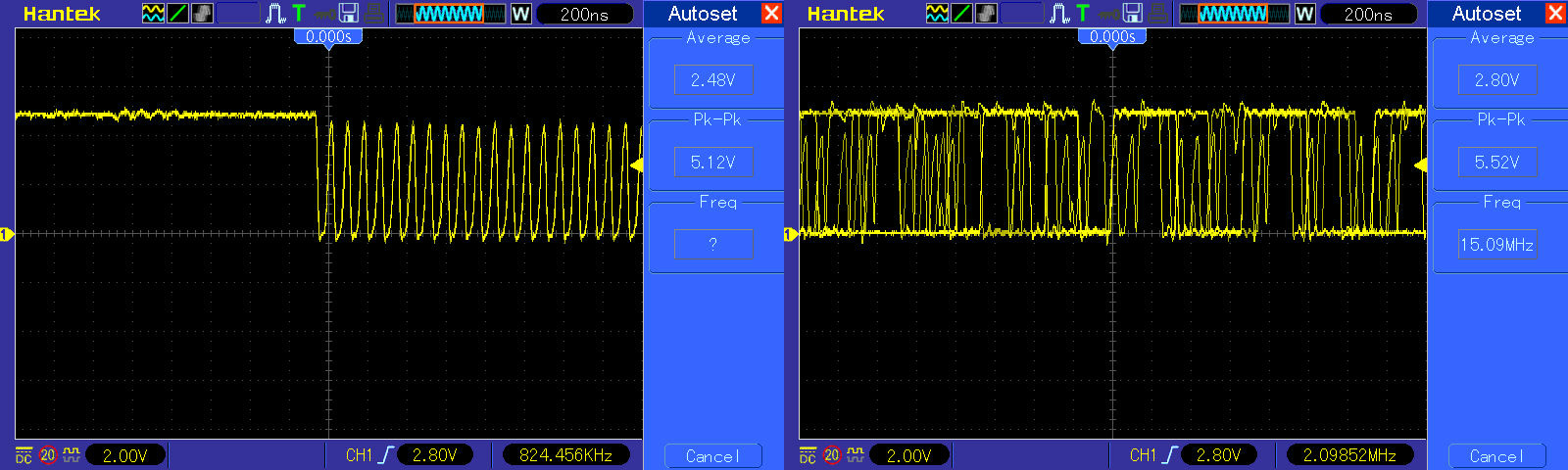
I went to probe each RAM with my scope and found some irregular activity on data lines of the chip @9K, here is a comparison with a good signal (on the left of the below picture)
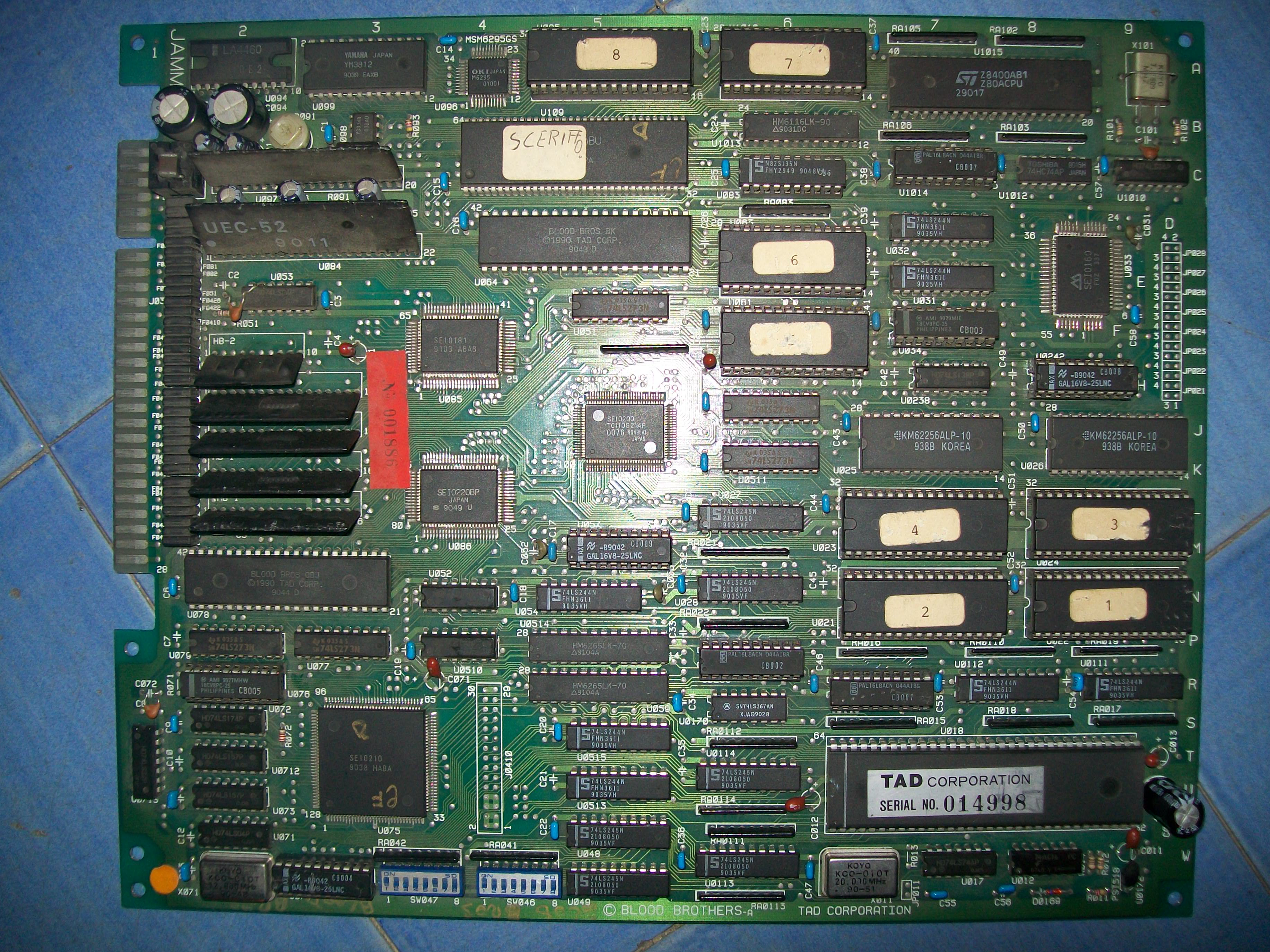
Got this original Blood Bros. among a lot of untested PCBs:
For the uninitiated Blood Bros. was released by Tad Corporation in the 1990 and can be considered the sequel of Cabal since it shares the same gameplay.
When I powered up my board, I didn’t noticed anything abnormal but once started a game the background GFX were flashing until they completely disappeared leaving black this part of screen :
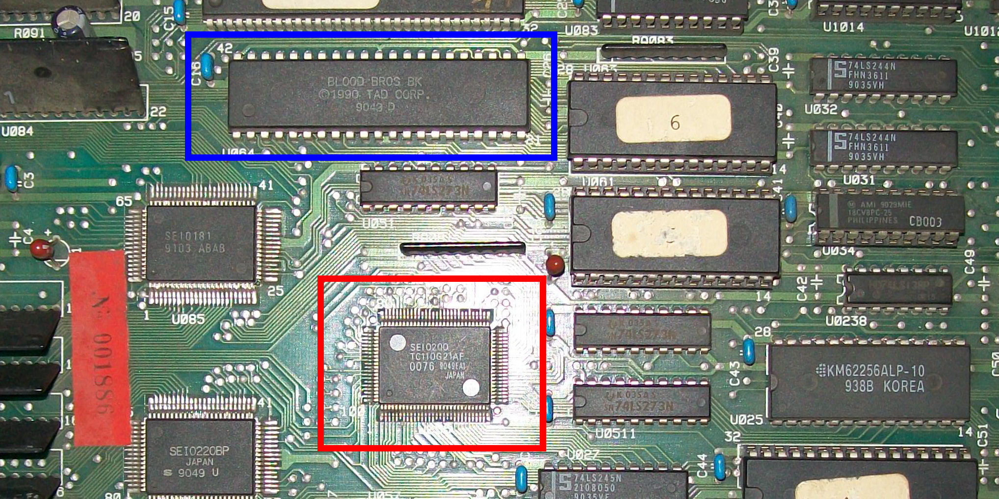
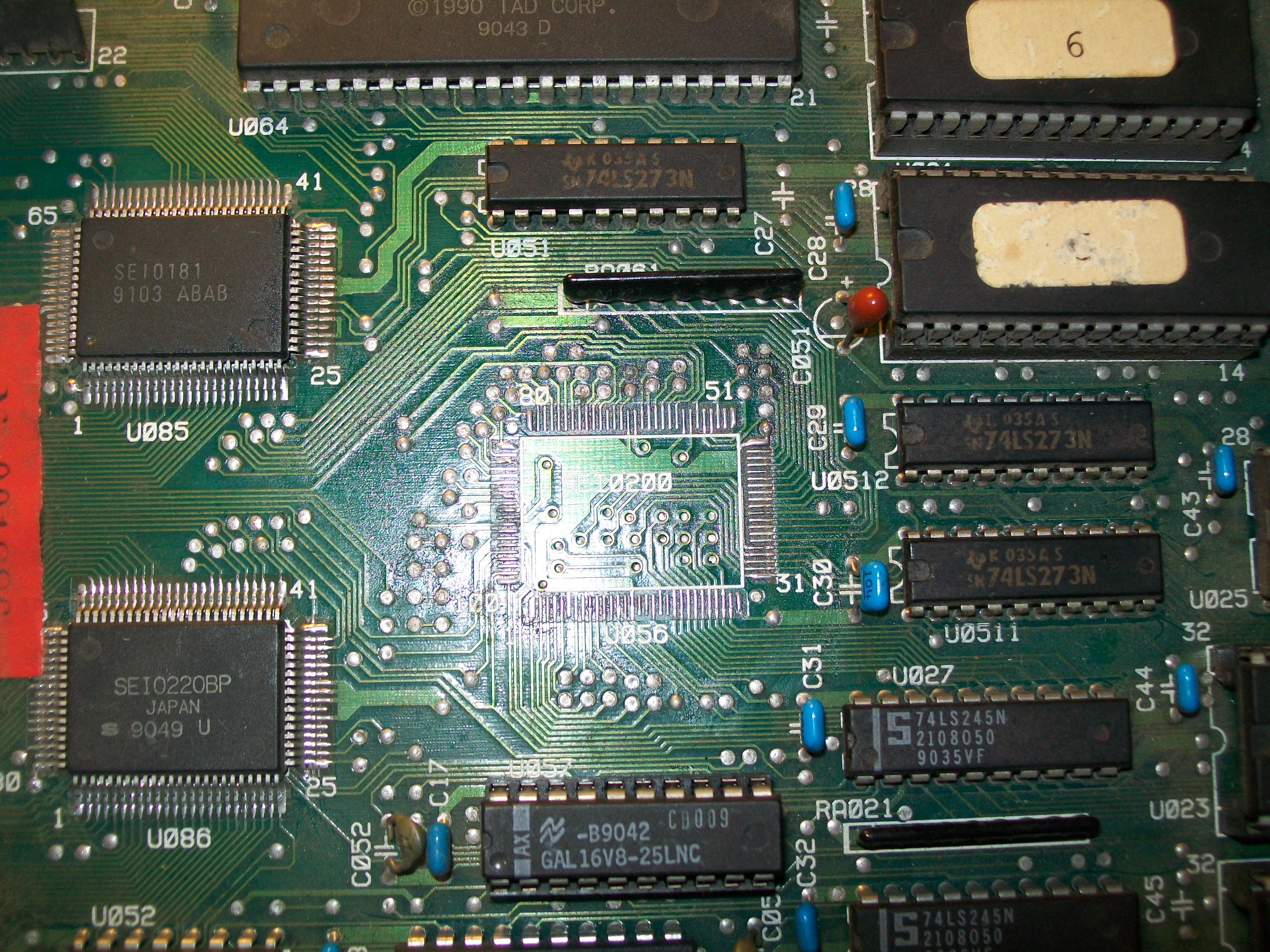
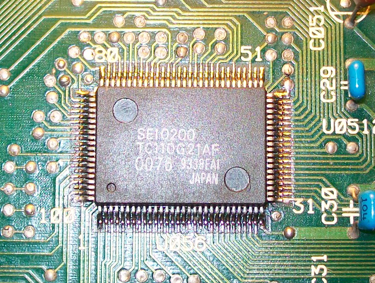
Board uses some customs ASIC to generate GFX.Studying a bit the hardware I figured out that the one marked ‘SEI0200 TC110G21AF’ 8QFP100) addresses the background/foreground 42 pin MASK ROM through some 74LS273 and processes directly its data :
Piggybacking a programmed 27C800 (equivalent to the 42 pin MASK ROM) had no effect.Since there were no other involved component I was pretty sure the ASIC was bad.Having a Raiden II as donor board I decided to replace this custom:
After some work the donor part was in place:
Powered up the board again and all the background GFX were back.Board 100% fixed.
The hardware of this matches Part II but it has the multigame add-on fitted.
Not worked on a Space Invaders board before and needed to make up a loom so I could properly test.
The owner says the ship is constantly pulling to the left and there is a sound effect playing over and over all the time.
On powering up I did indeed find these problems. Look at the video, the in game play shows me moving the ship to the right but when I release the controls it moves back far left on its own.
You can also hear the constant tone repeating over and over.
First of all I went looking for the control issue.
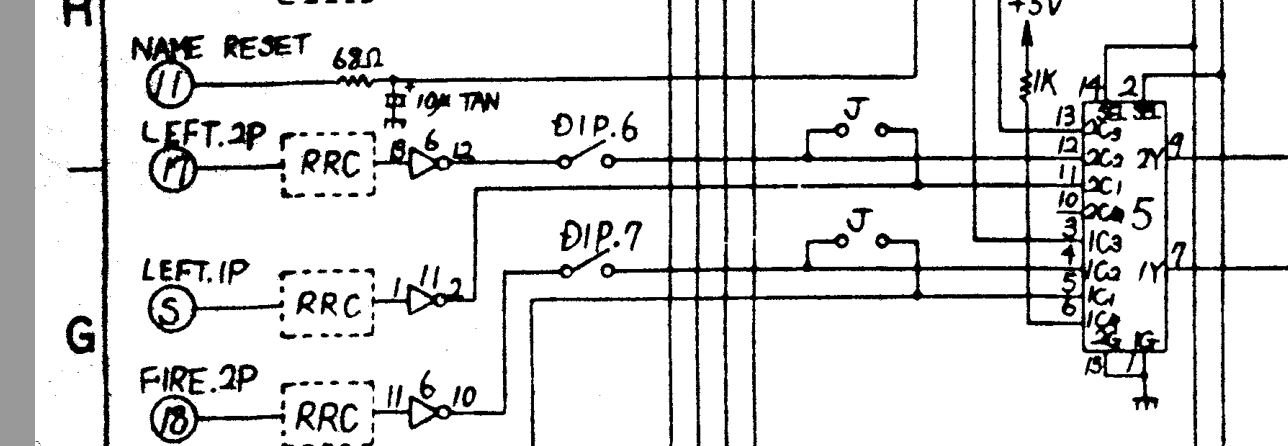
The schematics are available however they aren’t too great in places. Fortunately they were good enough to save me a lot of time.
Here you can see where the player 1 left comes in. It goes through an inverting buffer and into a 74153 chip at location 5. The output on pin 9 is the one we are concerned with
From my logic probe I could see that this output is stuck when it should be active. Testing this out of circuit confirmed it.
This fixed the control issue .
Now on to the sound fault.
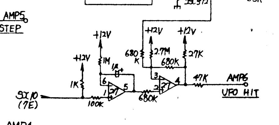
Space Invaders hardware made this quite easy as each sound effect has its own volume control. By turning the pots down I could pinpoint which sound was stuck on and work back from there.
VR7 was the pot associated with this sound and according to the manual this is the sound of the “UFO HIT”.
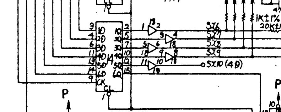
Looking at the schematics again and working backwards we can see it goes back to buffer chip 7417 at location 18 and before that it comes from a 74174 at location 14.
The outputs from the 74174 looked good but all the outputs from the 7417 buffer were stuck HIGH.
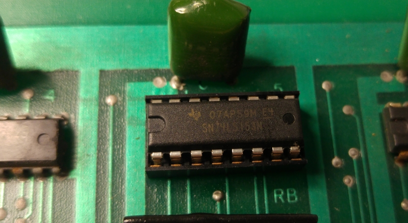
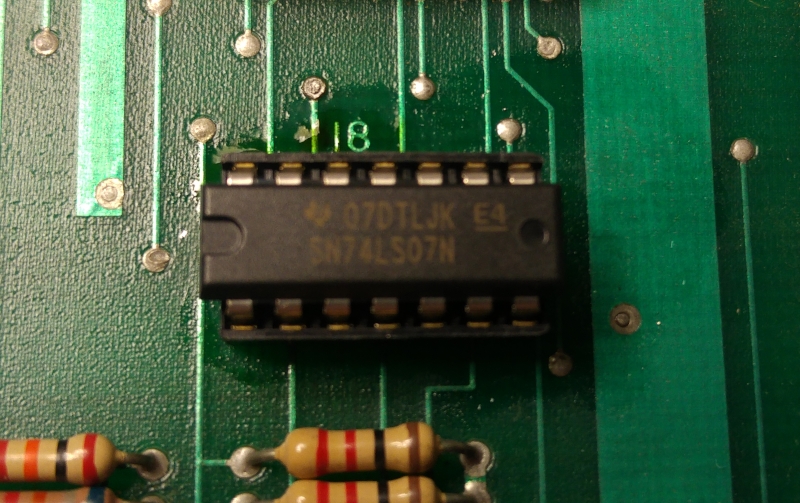
I removed the chip and once again it failed when testing out of circuit but now I had problem. I dont have any 7417 chips and I no longer have scrap PCB’s lying around.
The sadness was short lived as a quick google search revealed a 74LS07 chip can be used as a replacement and the difference between the two is the 7407 is rated for 30v where the 7417 is rated for 15v.
Anyway, replacing this with a 74LS07 worked and the sounds are all OK.
The video shows the controls now working and the lack of annoying sound. I did actually test the UFO HIT sound in game and it was working fine.
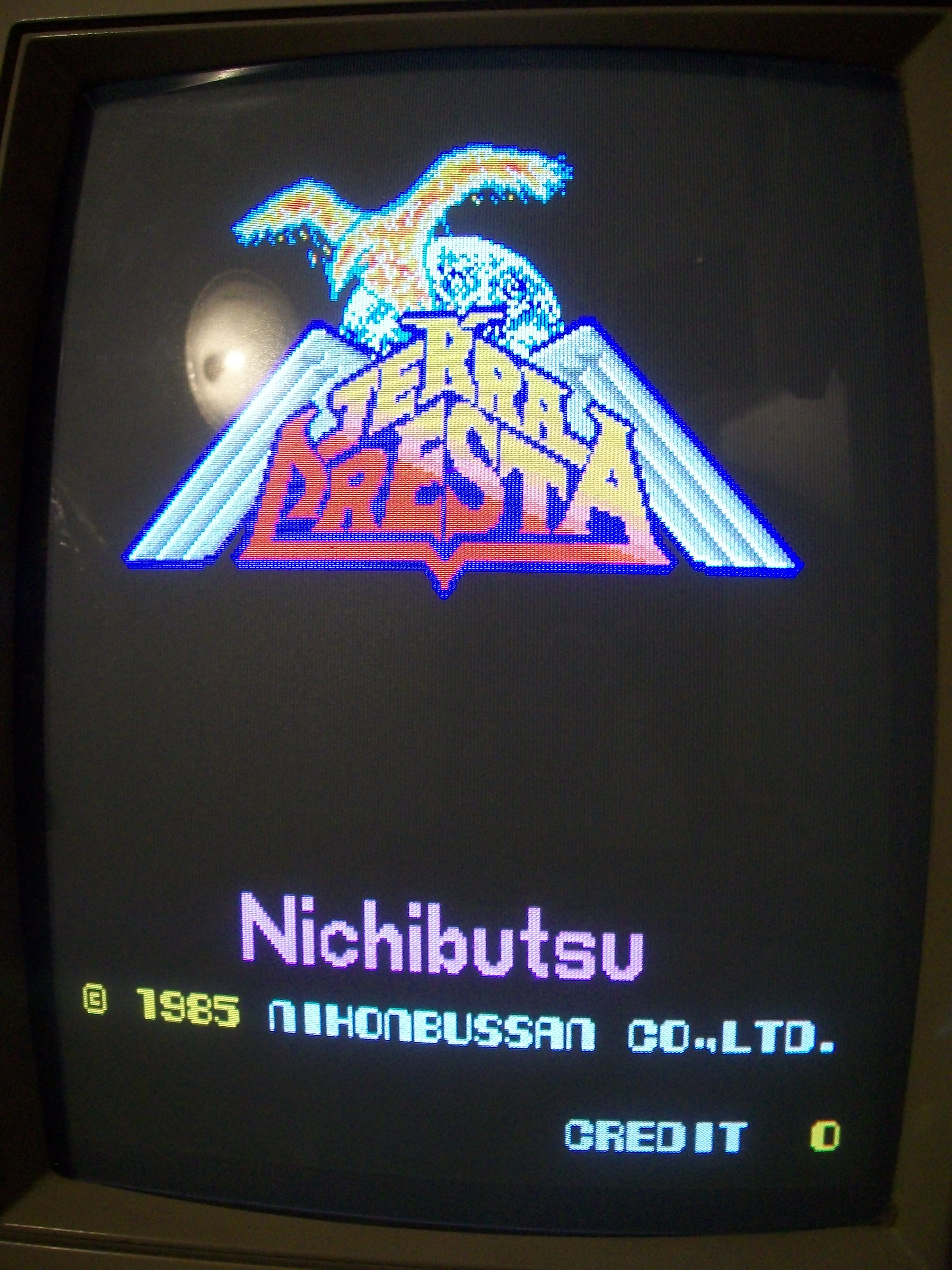
Received this original Nichibutsu Terra Cresta PCB for a repair:
Board had severe graphical issues, backgounds were all messed up and moving, sprites absent:
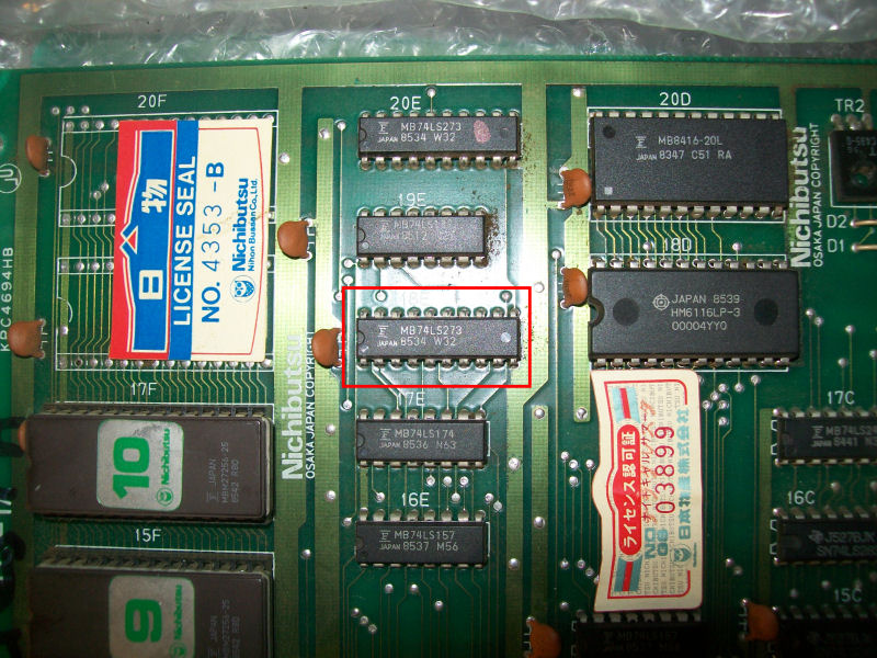
The first thing I noticed after my visual inspection was that both boards were fully populated with Fujitsu TTLs therefore I was pretty sure all the faults were due them.To troubleshoot them I used my HP10529A logic comparator for TTLs up 16 pin and a logic probe for 20 pin ones.The backgrounds data are stored in two 27256 EPROMs @15F and 17F on CPU board so I went to probe around and I found a 74LS273 @18E with stuck outputs:
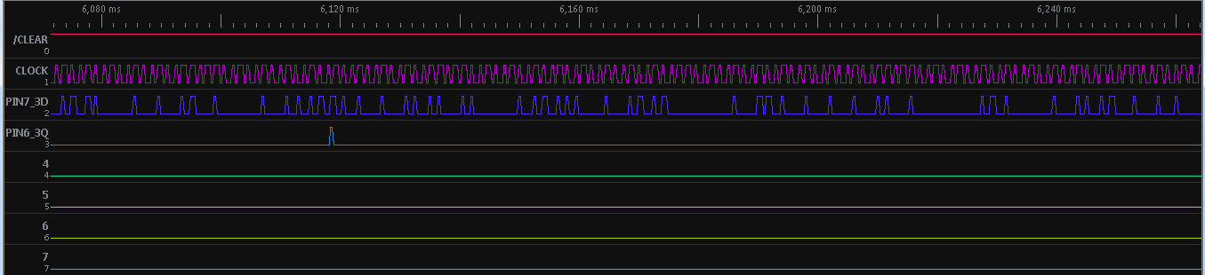
This was confirmed also by a logic analyzing of the device:
Once desoldered the device failed when tested out-of-circuit:
I got improvements, now backgorunds were almost formed but still scrambled and sprites visible although not perfect:
With my HP10529A I found a 74LS157 with floating outputs @17D on CPU board:
Chip failed the out-of-circuit test:
Backgrounds were now 100% restored but sprites missing lines with some garbage on screen :
At this point I focused on video board since all objects circuitry lies there :
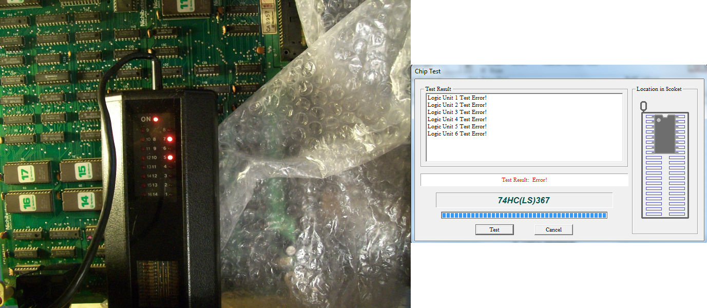
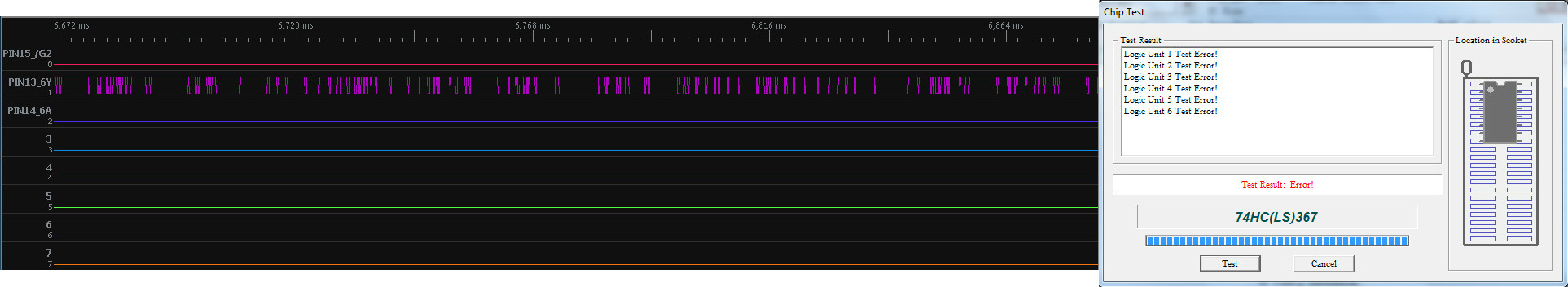
Probing around the sprites EPROMs, I found a 74LS367 @1F with bad outputs:
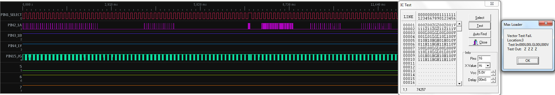
and a 7LS257 @3C (involved in sprites RAM data bus) with stuck outputs, also this failed its test:
Now sprites were perfect but doing some comparison with MAME I realized that characters were totally missing!
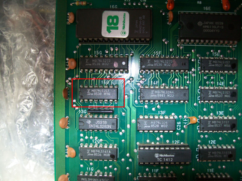
Found a 74LS257 @14G with missing input pin 15 (/OE ) in the area of the character ROM:
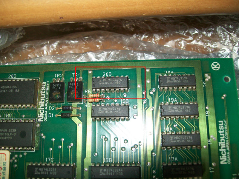
I traced it back to an output of a 74LS367@20B on CPU board:
Logic analyzing confirmed its outputs were floating and chip failed once tested out-of-circuit:
Characters were back:
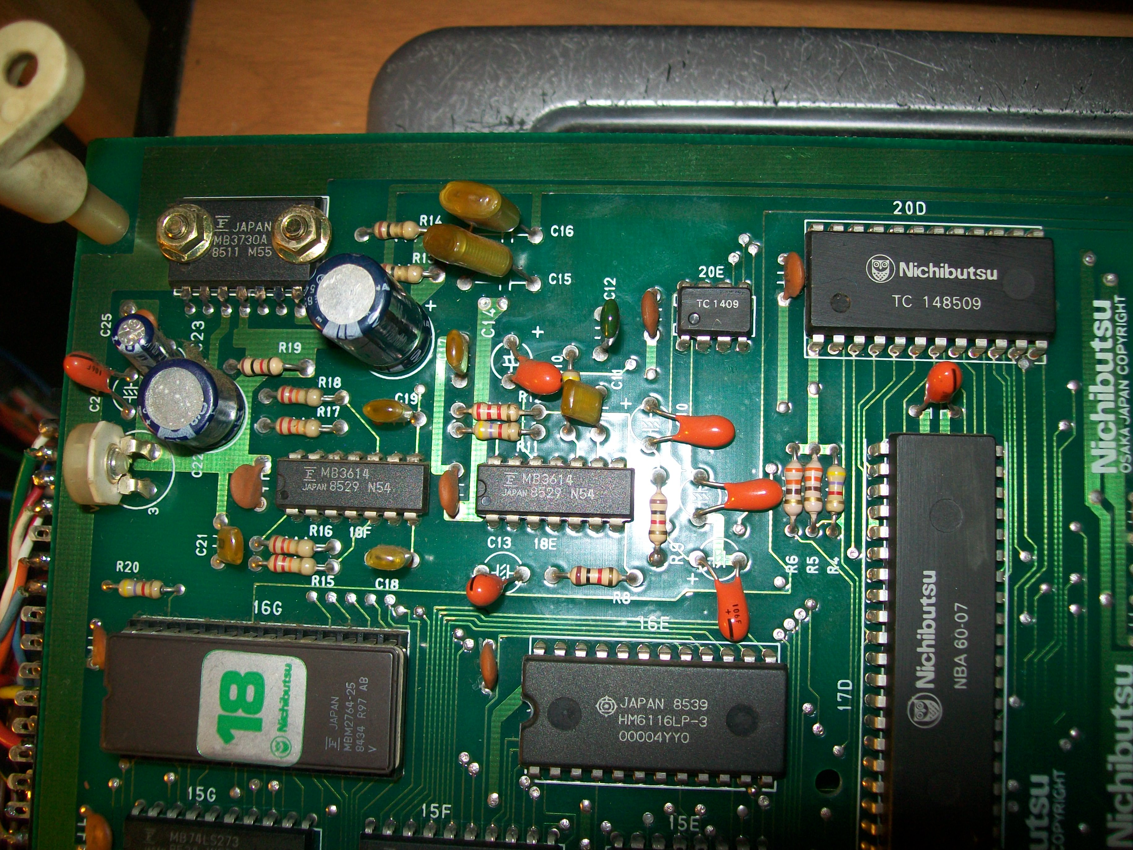
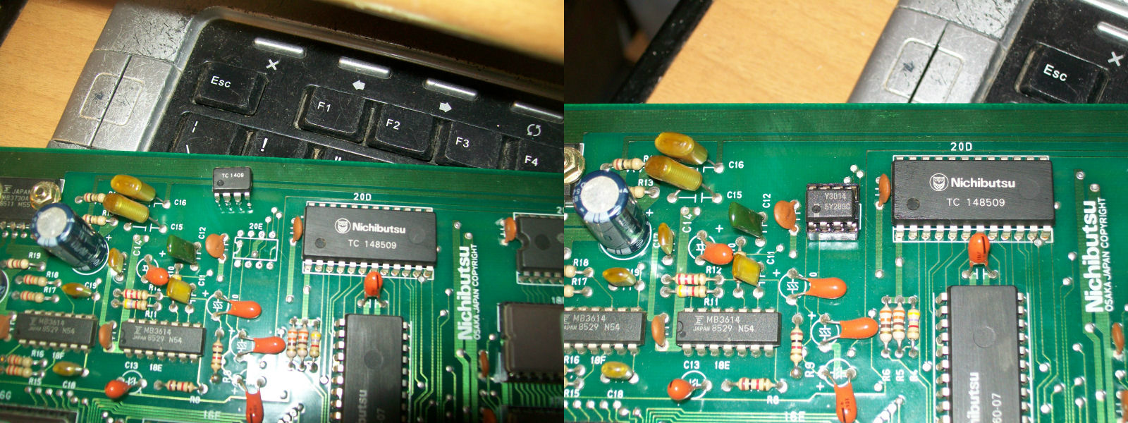
I was archiving this repair when, during my test, I experienced some sound issues, sometimes audio was distorted:
This board uses an YM3526 OPL IC paired with an YM3014 DAC although chips are marked with Nichibutsu part name (‘TC 148509’ and ‘TC 1409’) :
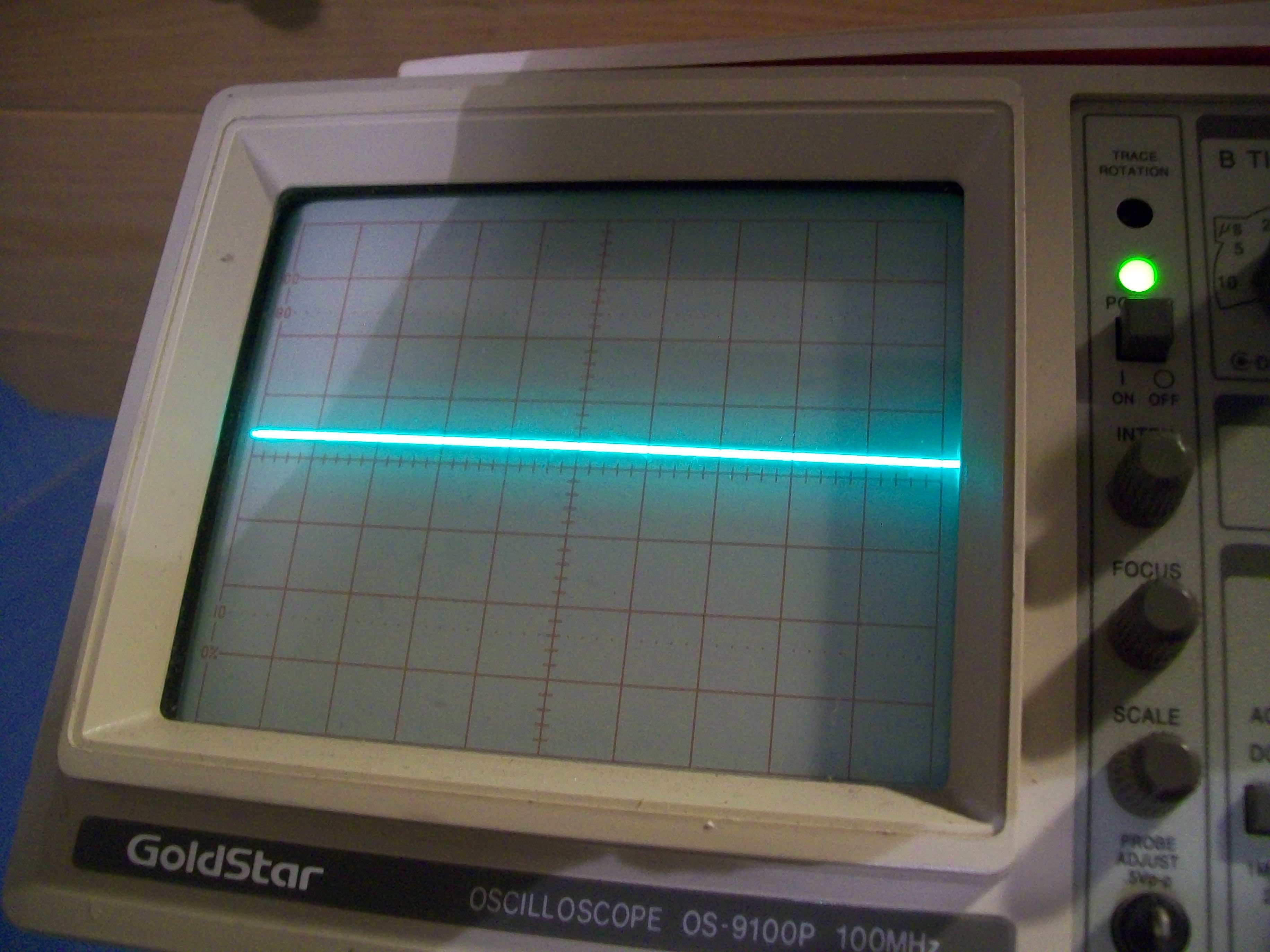
Probing pin 2 (the analog output connected to the OP-AMP) of the ‘TC 1409’ revealed a weak signal:
I replaced it with a YM3014 :
This gave good sound back.Board 100% fixed and evil Fujitsu once again defeated.