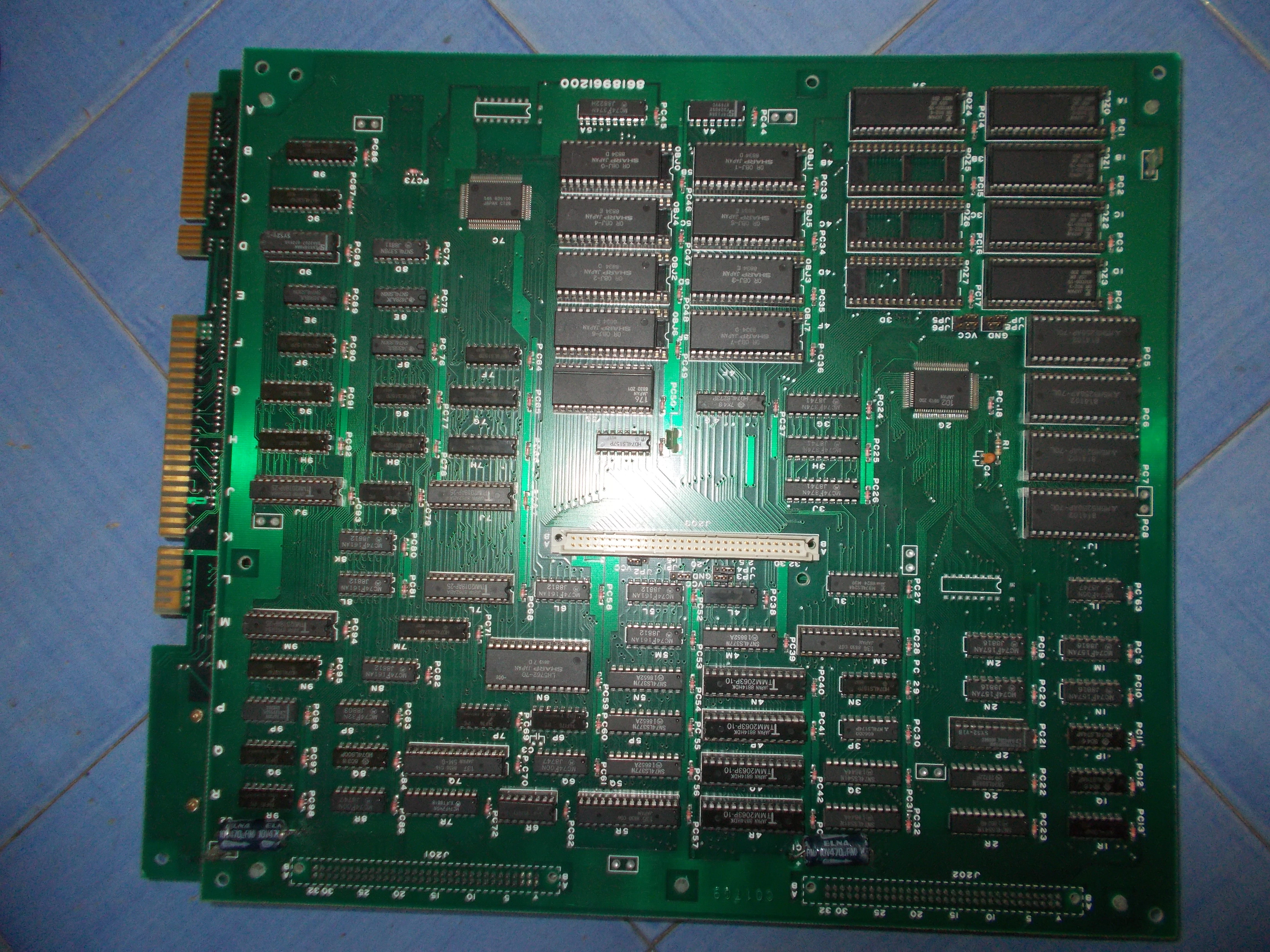
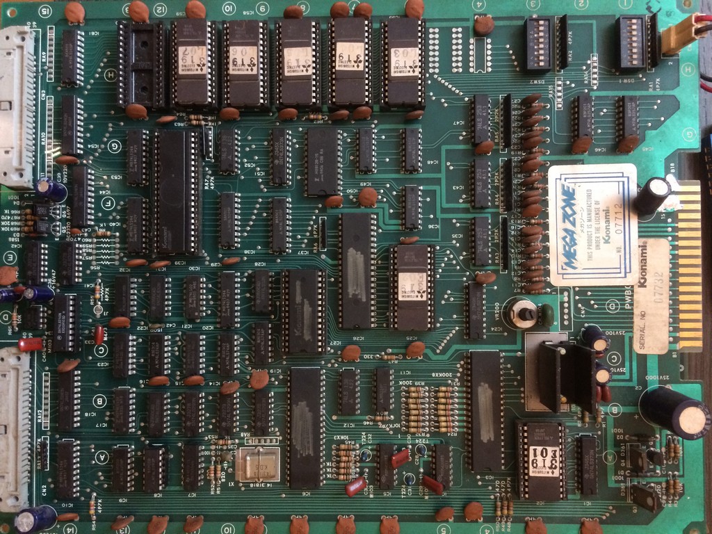
Got this faulty pcb for my collection
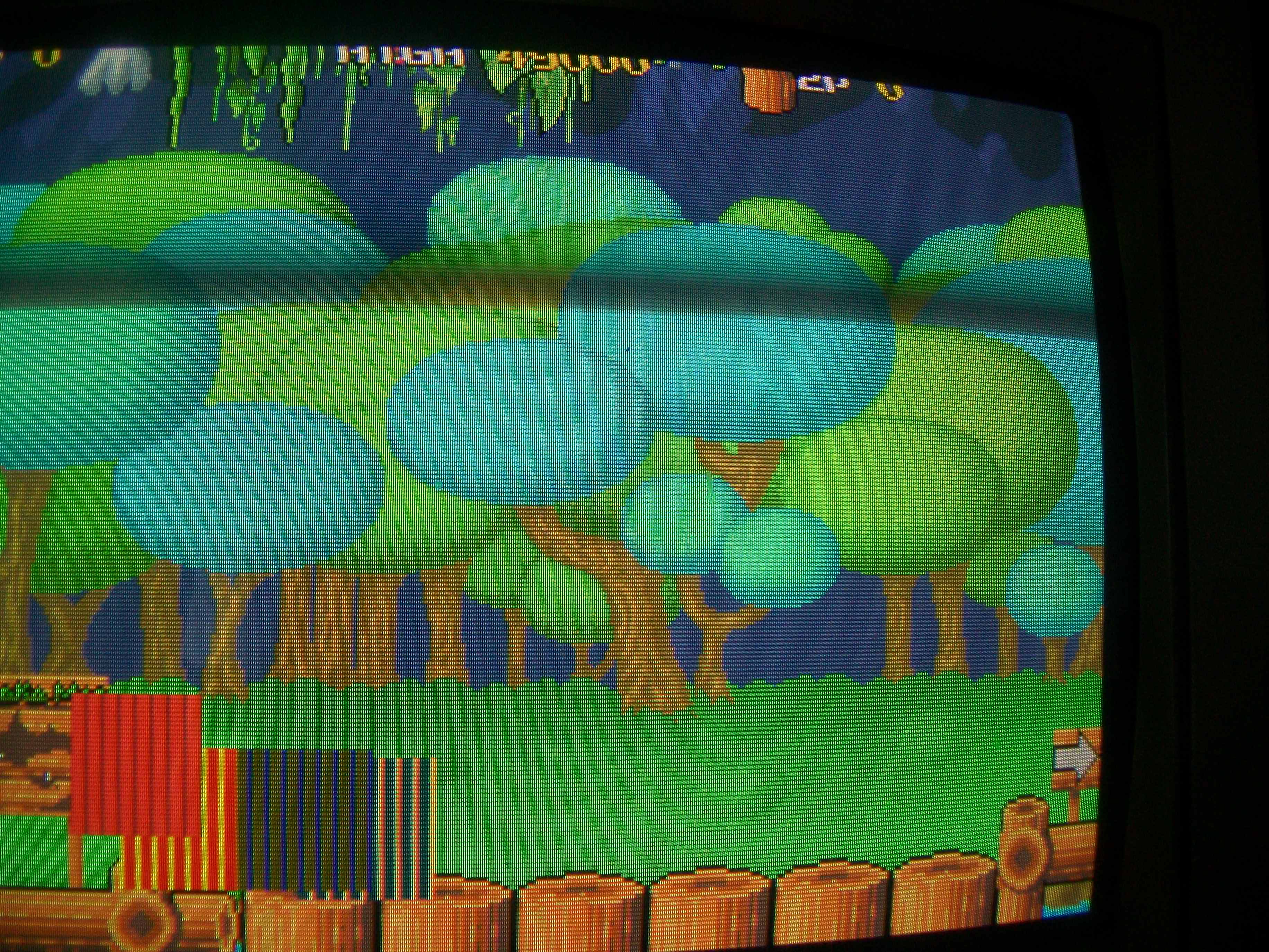
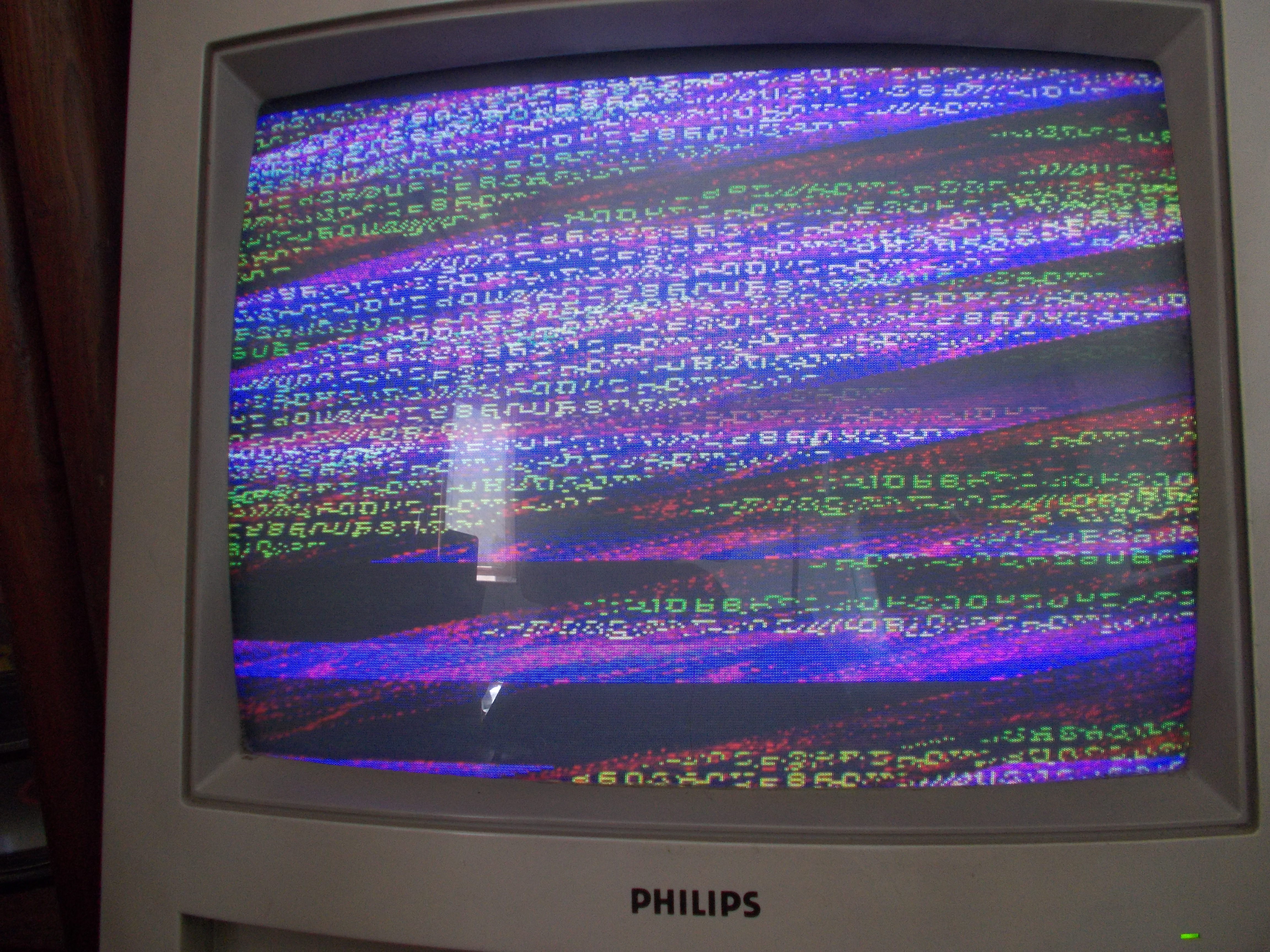
Game was resetting over and over right after the first stating screen without even the possibility to see the diagnostic screen “RAM ROM OK”
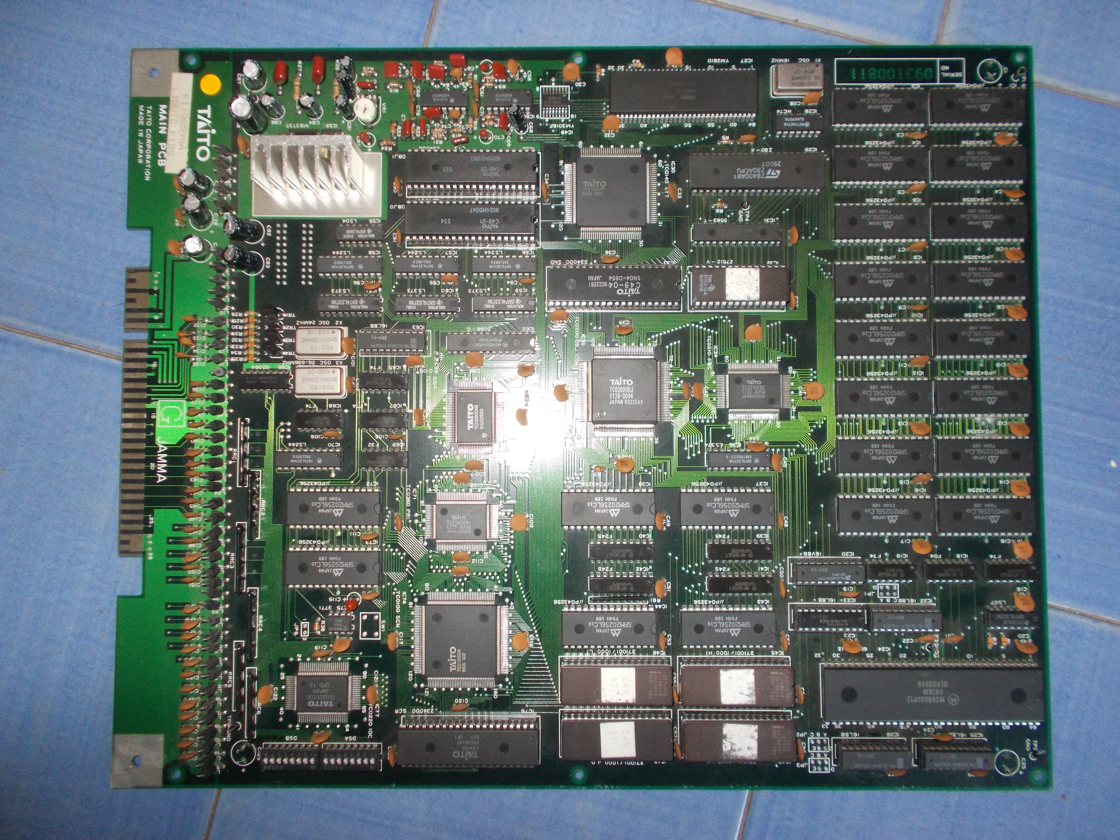
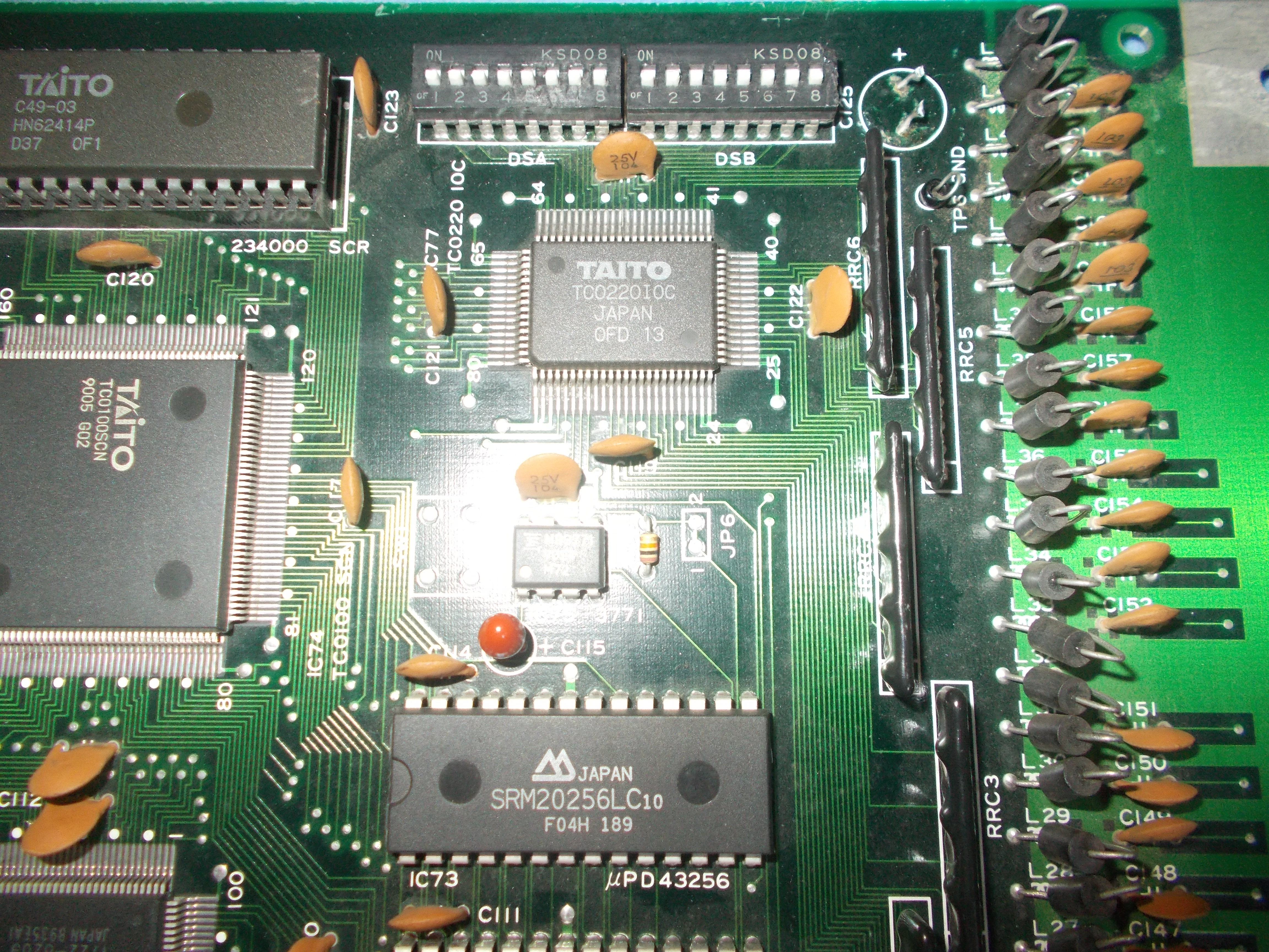
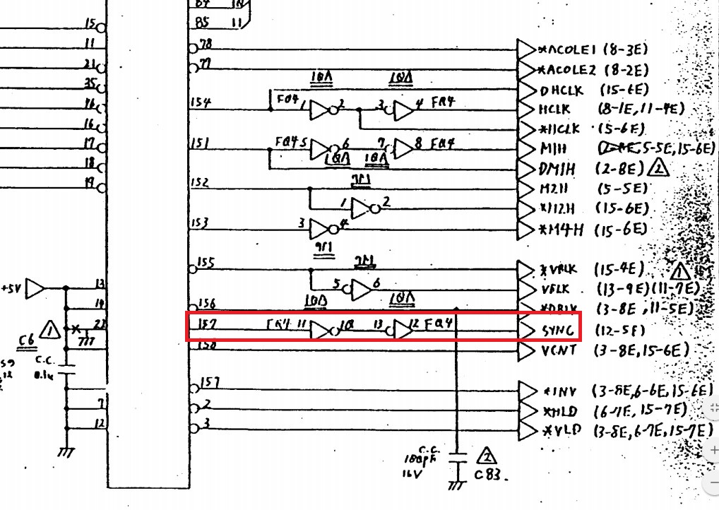
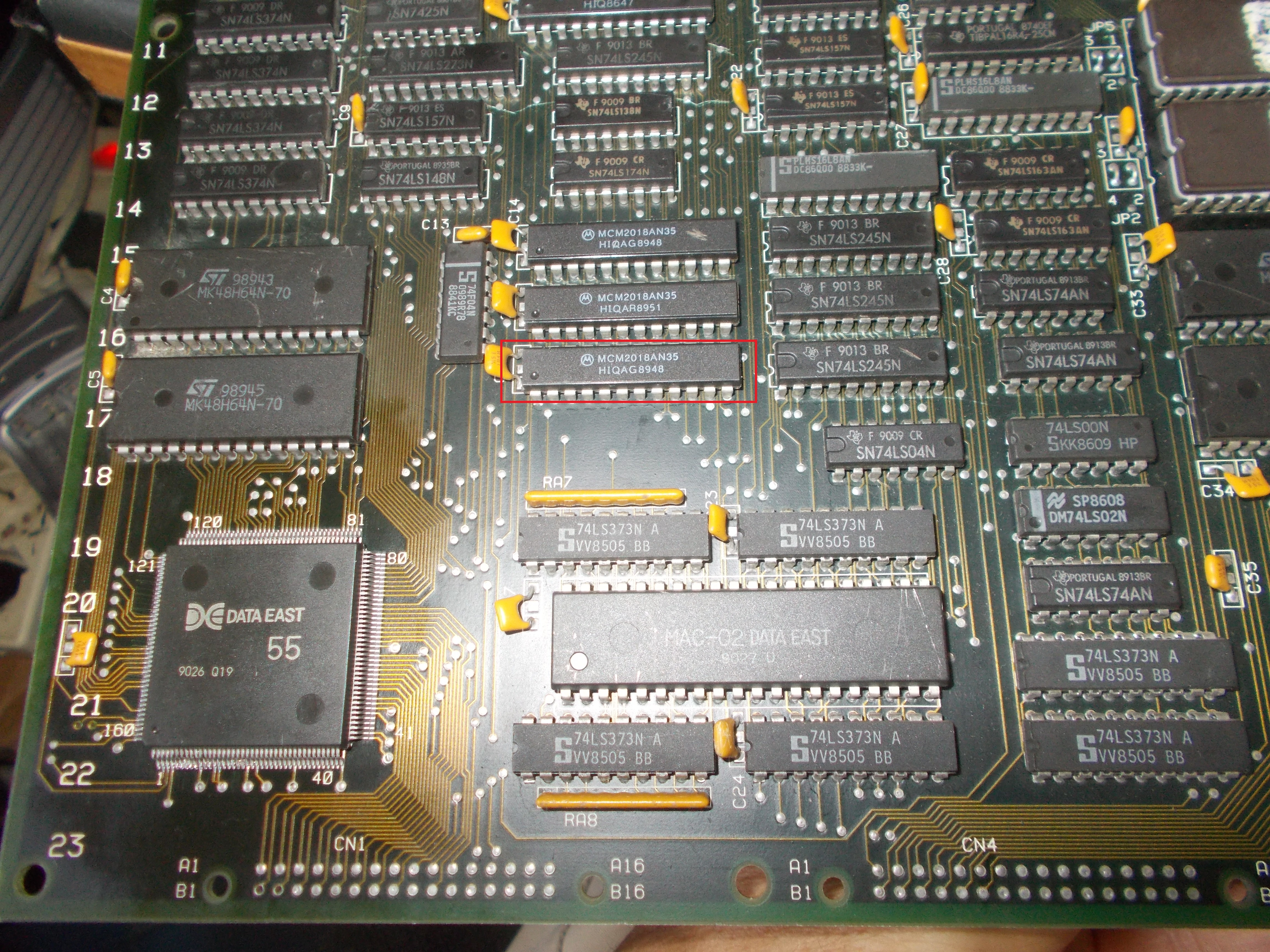
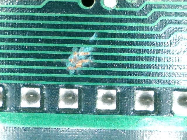
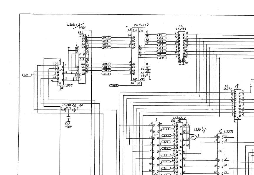
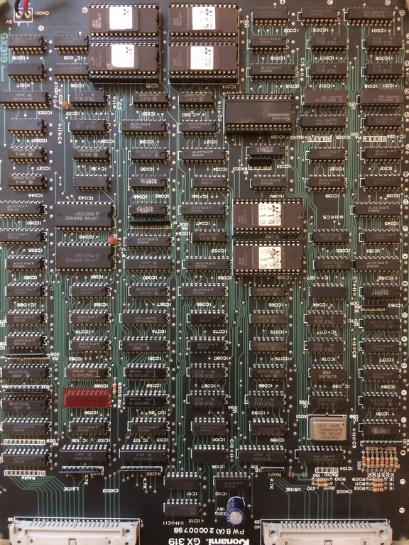
The code was running and the watchdog was triggered by some event which I eventually found in a faulty 2114 SRAM @E15 on the video board
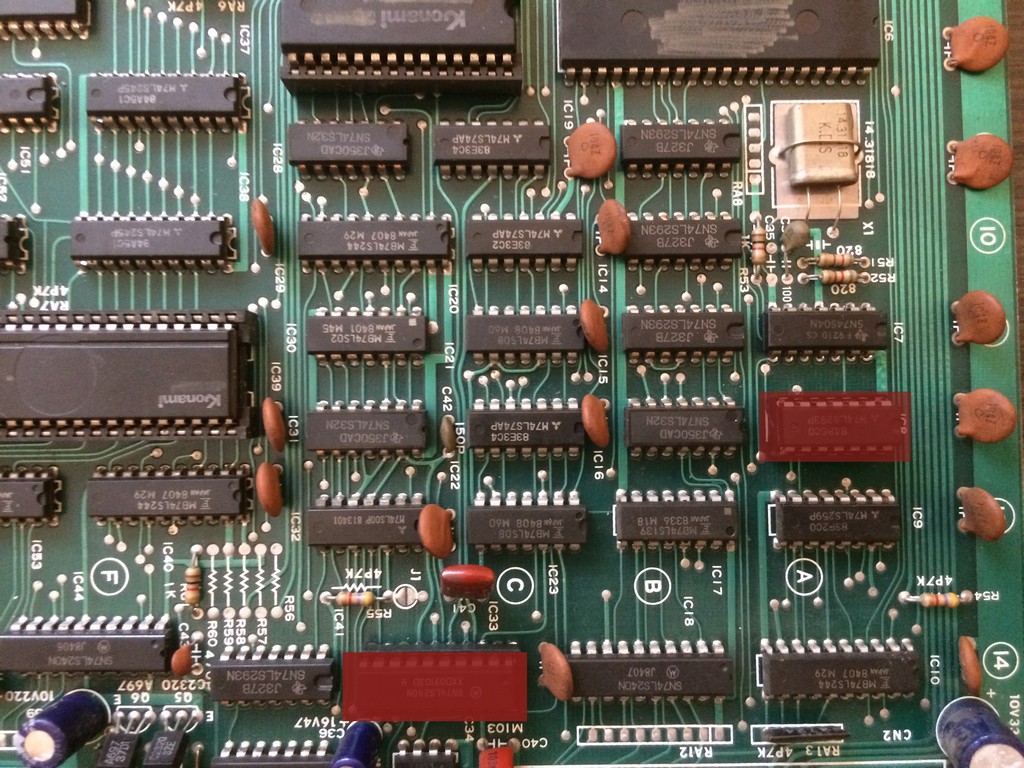
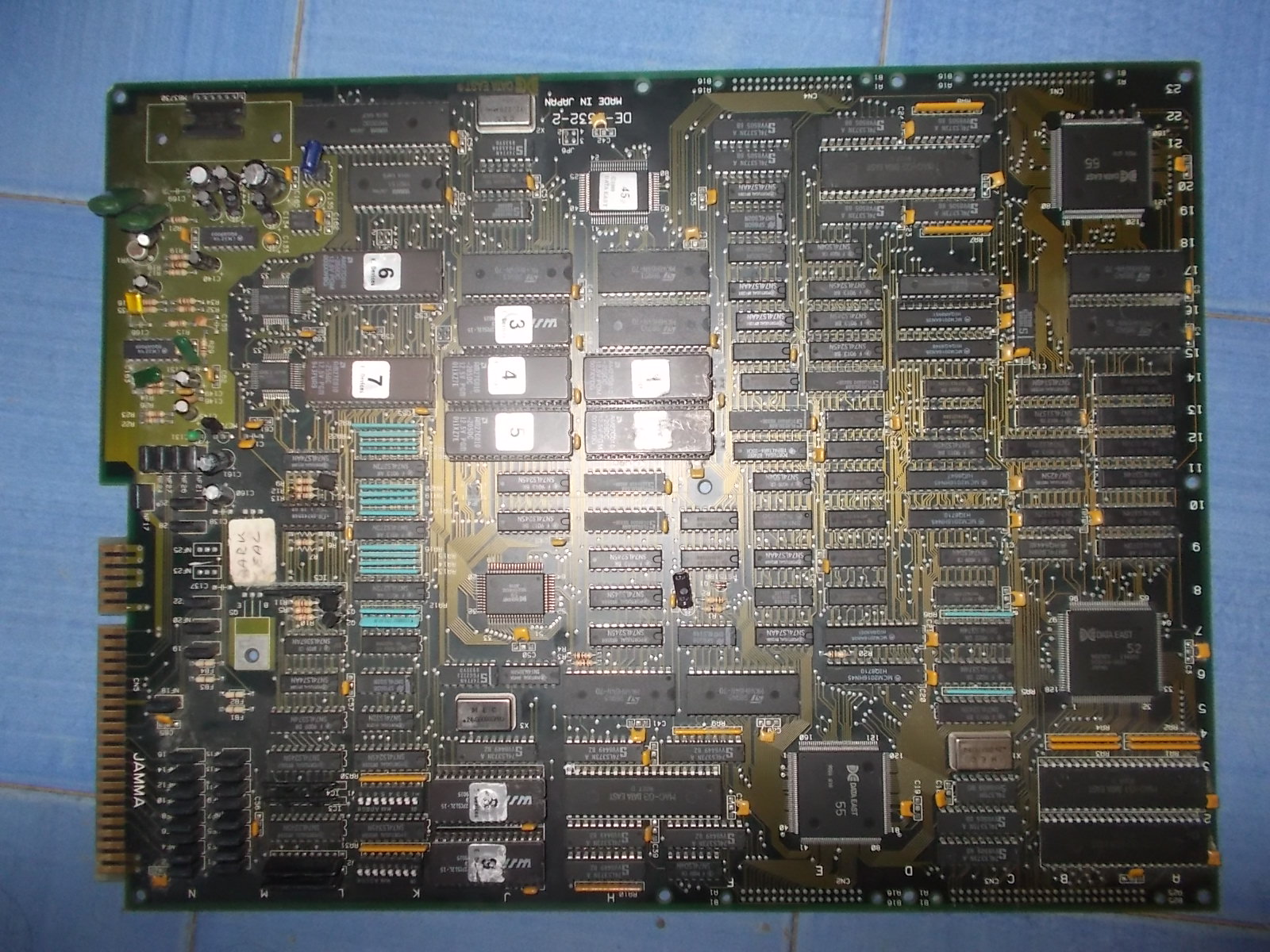
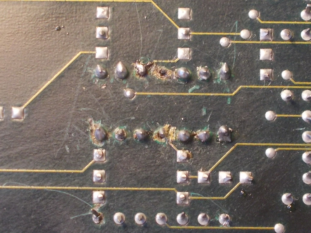
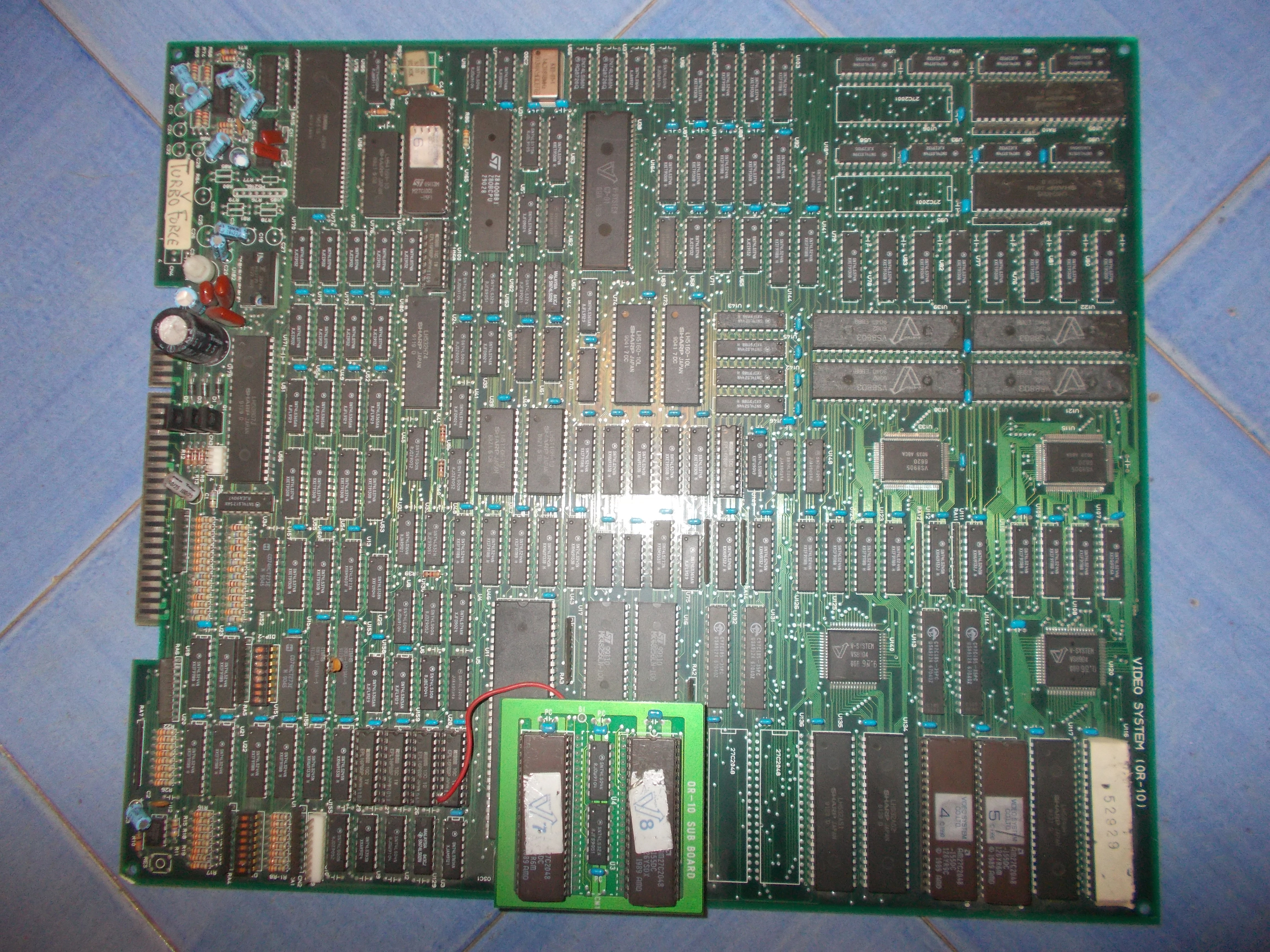
Marked in red on the actual pcb:
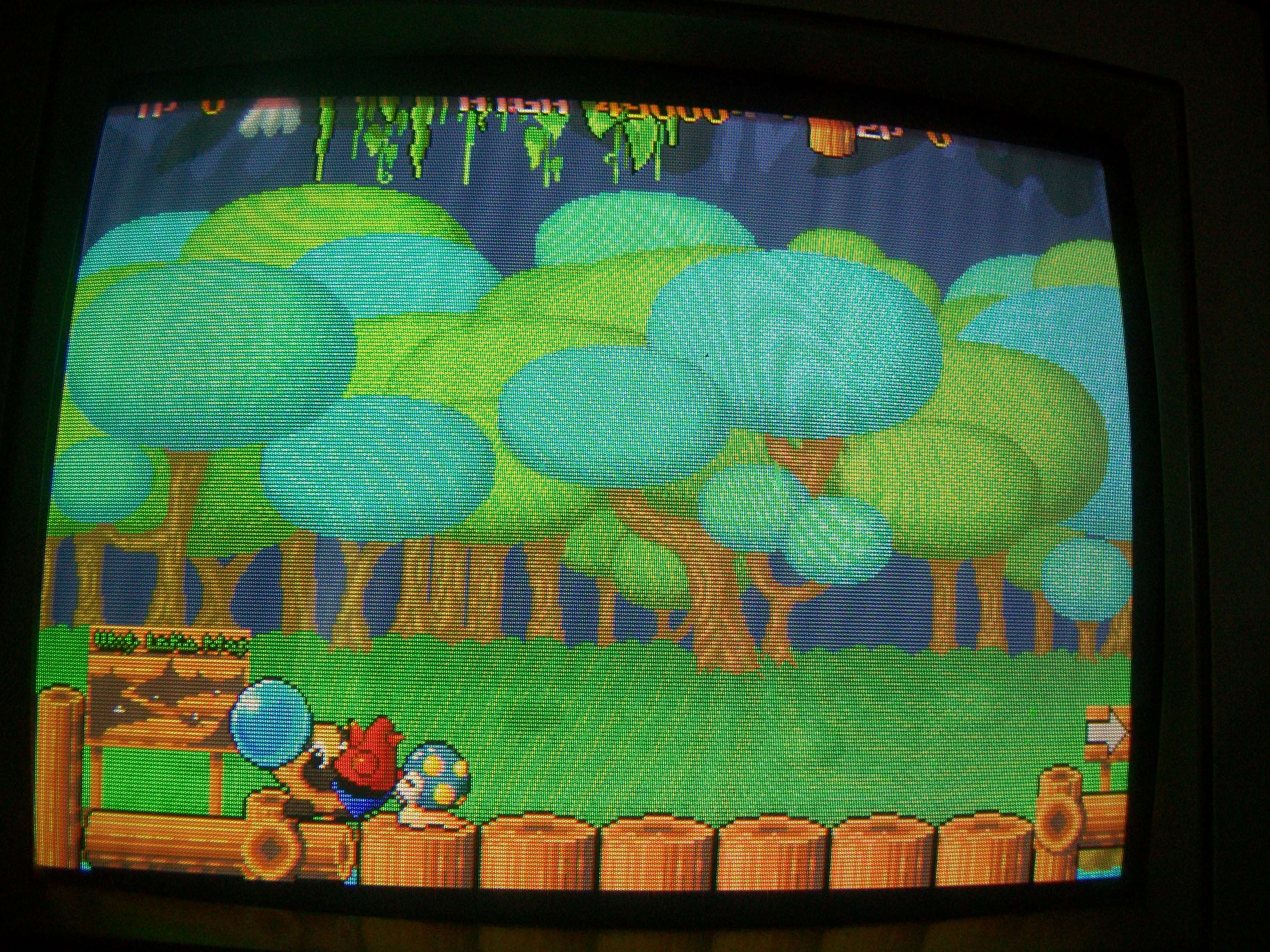
After changing it, the boot process went on until it displayed RAM and ROM OK but it reset again just before screen with the white grid.
At this time I was complete blind , missing any programming skills I couldn’t check what the code missed to go on.
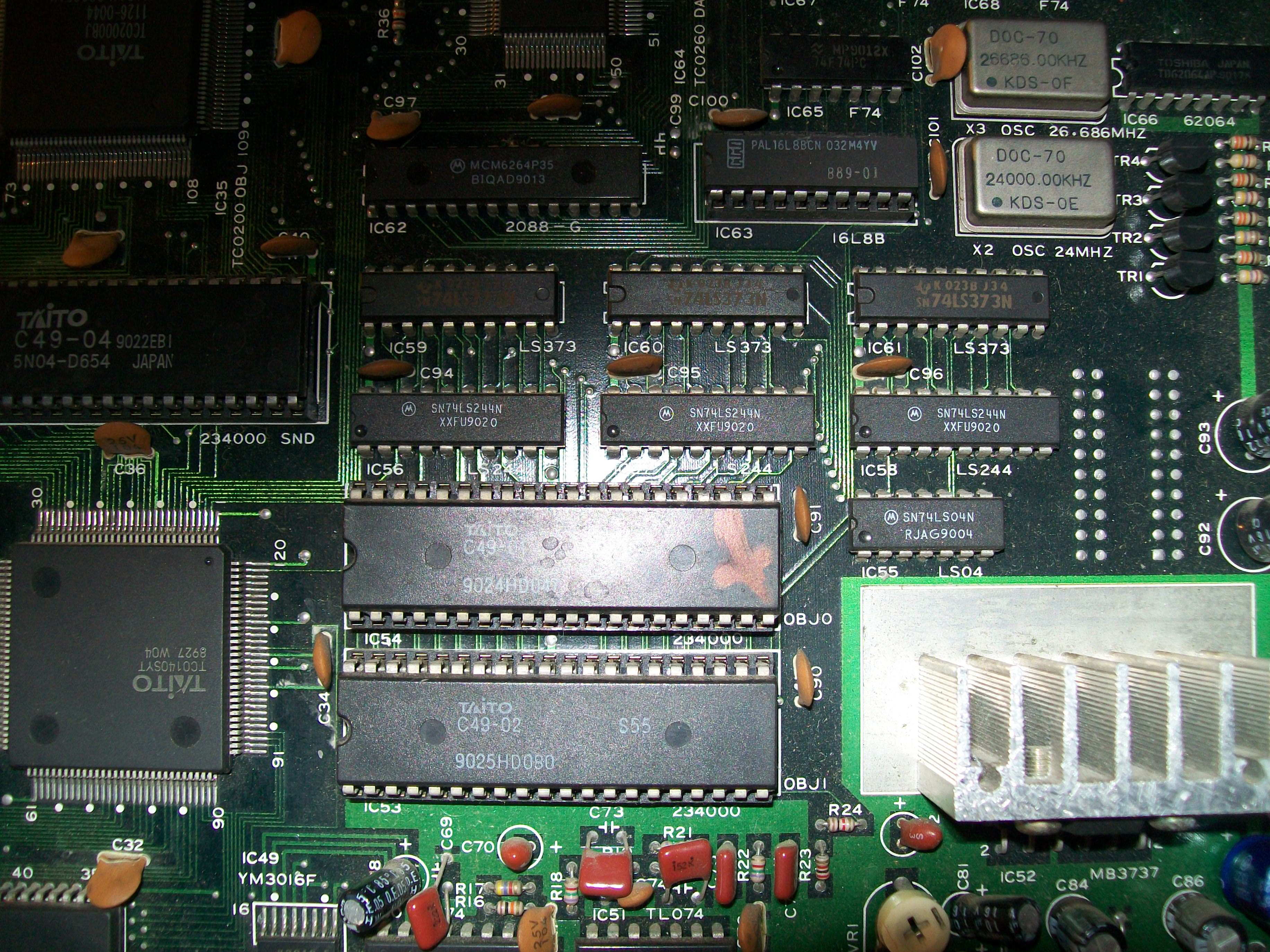
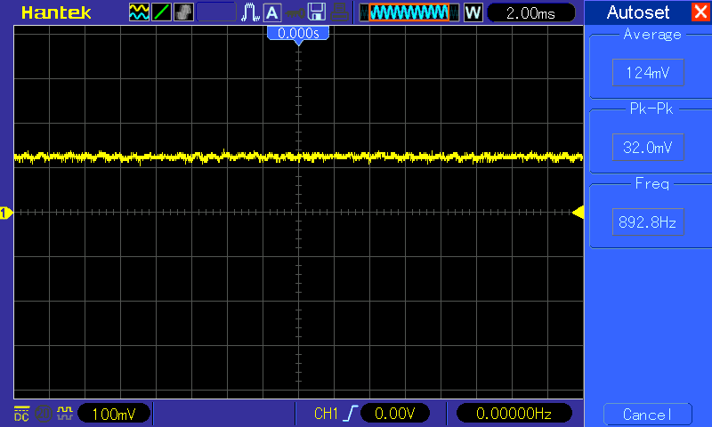
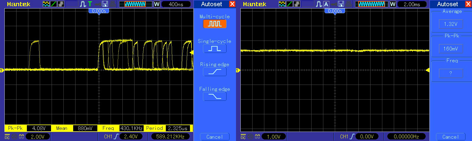
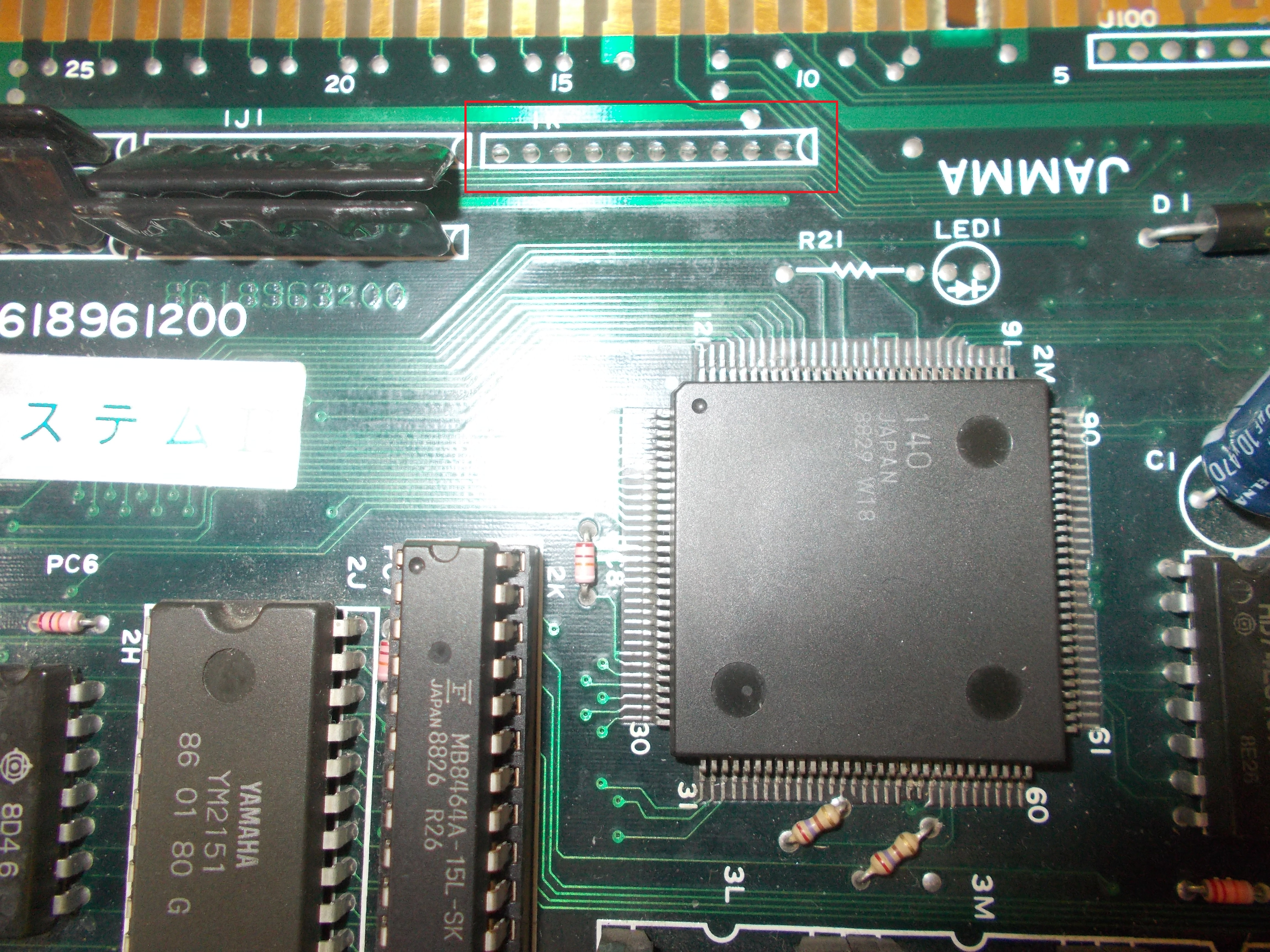
I had a suspect on the sound part and after checking the clocks on the 8039 MCU I noticed it was completely missing.
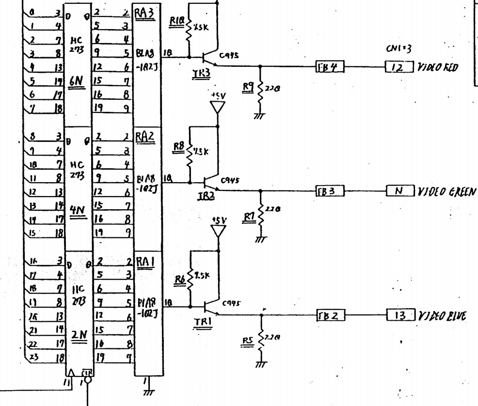
The oscillator was working correctly and from the schematics I could see that the clock for the 8039 and the AY is generated using some 4bit binary counters 74ls293, very difficult to find on other boards.
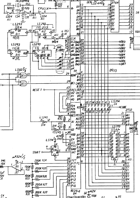
Probing pin 9 of 74ls293@A12 it was stuck high while on pin 10 I had the clock.
I proceeded to test it out of circuit but was tested good.
Not sure about the reliability of the tester, I found a Starforce boot which use one 74ls293 and I installed it in a socket on megazone.
Still reset and no clock from pin 9
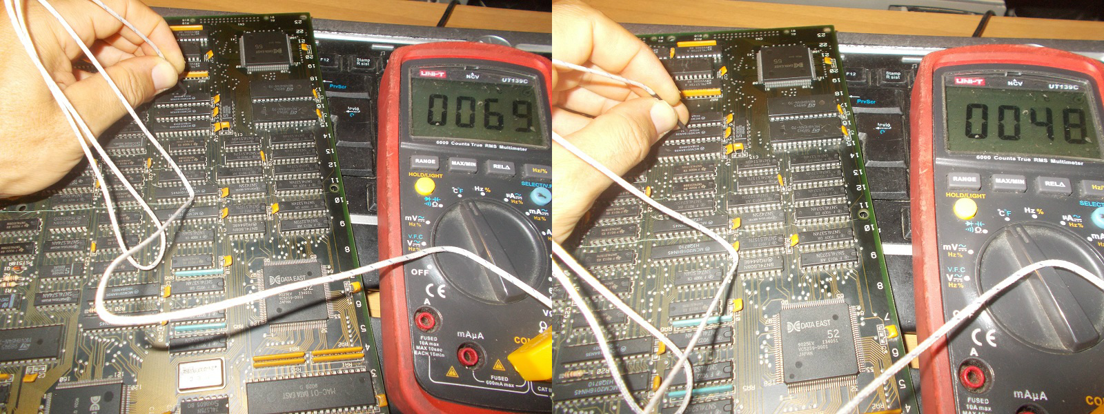
The output of the IC@A12 goes to pin 8 of a 74ls240, therefore I decided to test pin 8 of IC @D14 against +5V and it gave me a short.
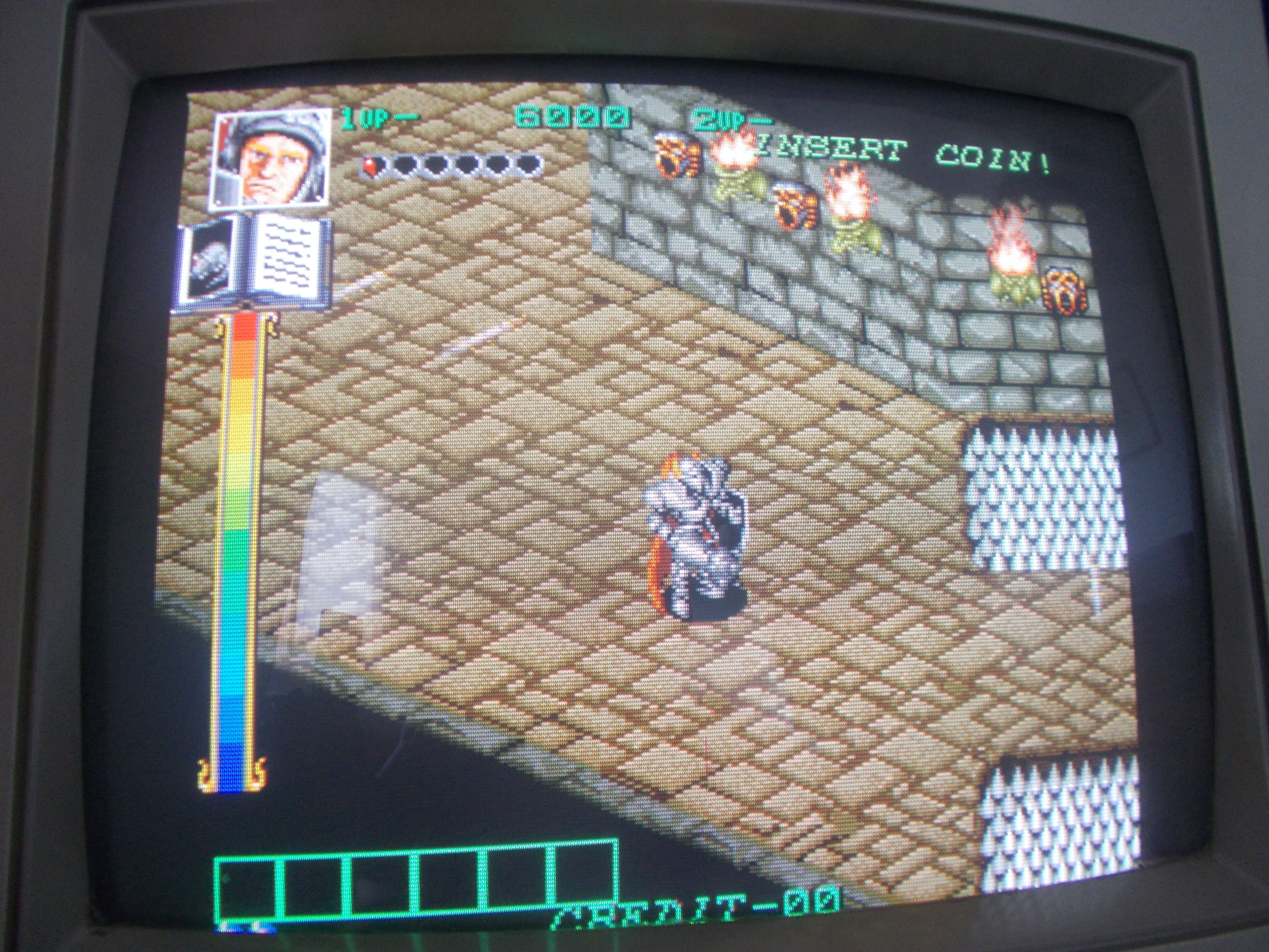
After changing it the game finally booted without any other faults